

JL Audio SB-N-PTHFNDR2-10W3v3-BK, SB-N-PTHFNDR2-10W3v3, SB-N-PTHFNDR2-10W3v3-LT User Manual
Page 1
SB-N-PTHFNDR2/10W3v3
2005 - Up
Nissan Pathfinder
SB-N-PTHFNDR2/10W3v3_INSTR_SKU#011234
SB-N-PTHFNDR2/10W3v3_INSTR_SKU#011234
2
INSTALLATION GUIDE
for the
SB-N-PTHFNDR2/10W3v3
2005 - Up
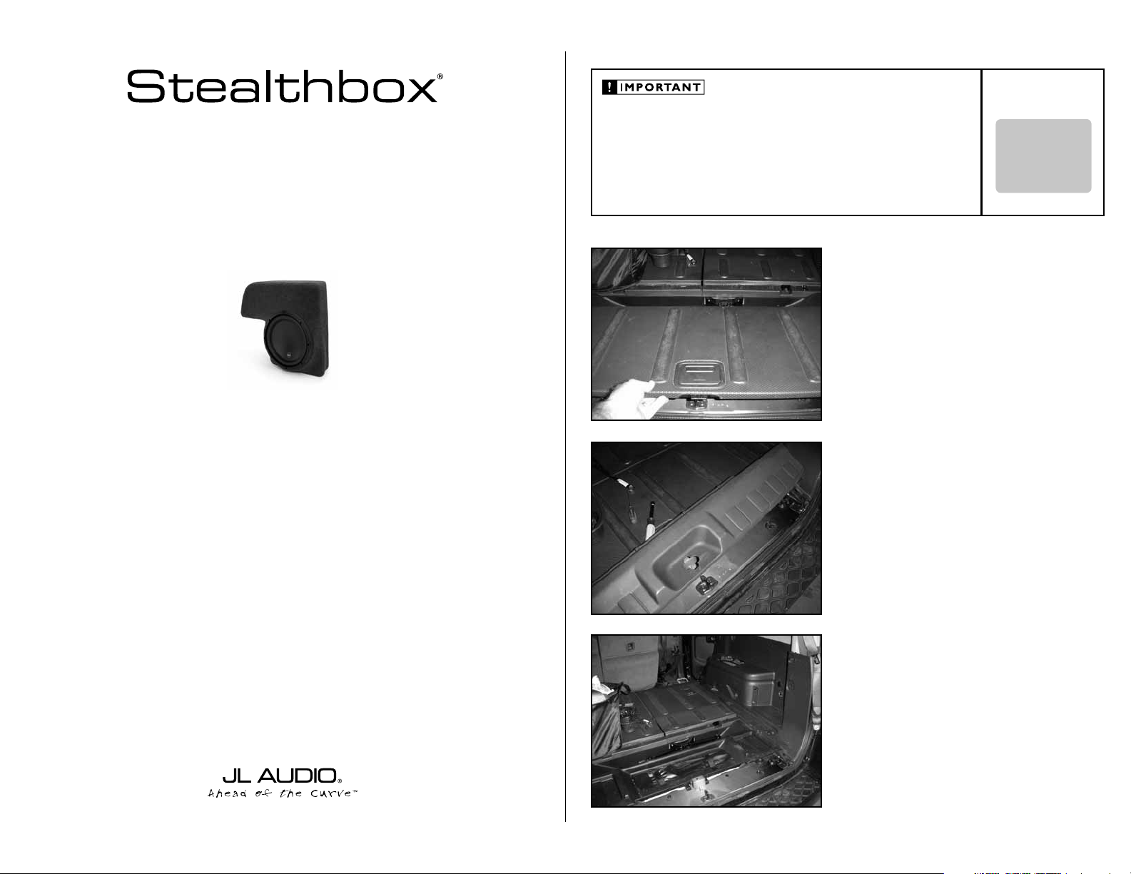
Thank you for choosing a JL Audio Stealthbox® for your automotive sound system. With proper
installation, your new vehicle-specific enclosed subwoofer system will deliver years of listening pleasure.
Nissan Pathfinder
If you choose to perform the installation yourself, it is absolutely vital that
the Stealthbox
instructions. Failure to mount the enclosure properly presents two problems:
1) The sub-bass performance will suffer due to the movement of the enclosure
caused by the force exerted by the woofer(s).
2) A loose enclosure presents a serious safety hazard in the event of a collision
or sudden deceleration.
®
be properly mounted to the vehicle according to these
STEP 1
Remove all contents from the rear cargo area.
Collapse the rear seating.
Remove the flooring out of the cargo area.
STEP 2
Remove the tailgate’s bottom sill plate.
INSTALLATION
DIFFICULTY:
OUT
OF
5
We strongly recommend that you have your new Stealthbox® installed by your authorized JL Audio
dealer. The installation professionals employed by your dealer have the necessary tools and experience
to disassemble and reassemble your vehicle properly. Also, keep in mind that your warranty coverage
extends to 1 year if your system is installed or approved by your authorized JL Audio dealer. If you
prefer to perform your own installation, please read this installation guide completely
before beginning the process.
STEP 3
The passenger side rear side panel needs to be removed
from the vehicle. Follow STEPS 4 - 13 in detail.
Continued on Next Page
Page 2
SB-N-PTHFNDR2/10W3v3_INSTR_SKU#011234
SB-N-PTHFNDR2/10W3v3_INSTR_SKU#011234
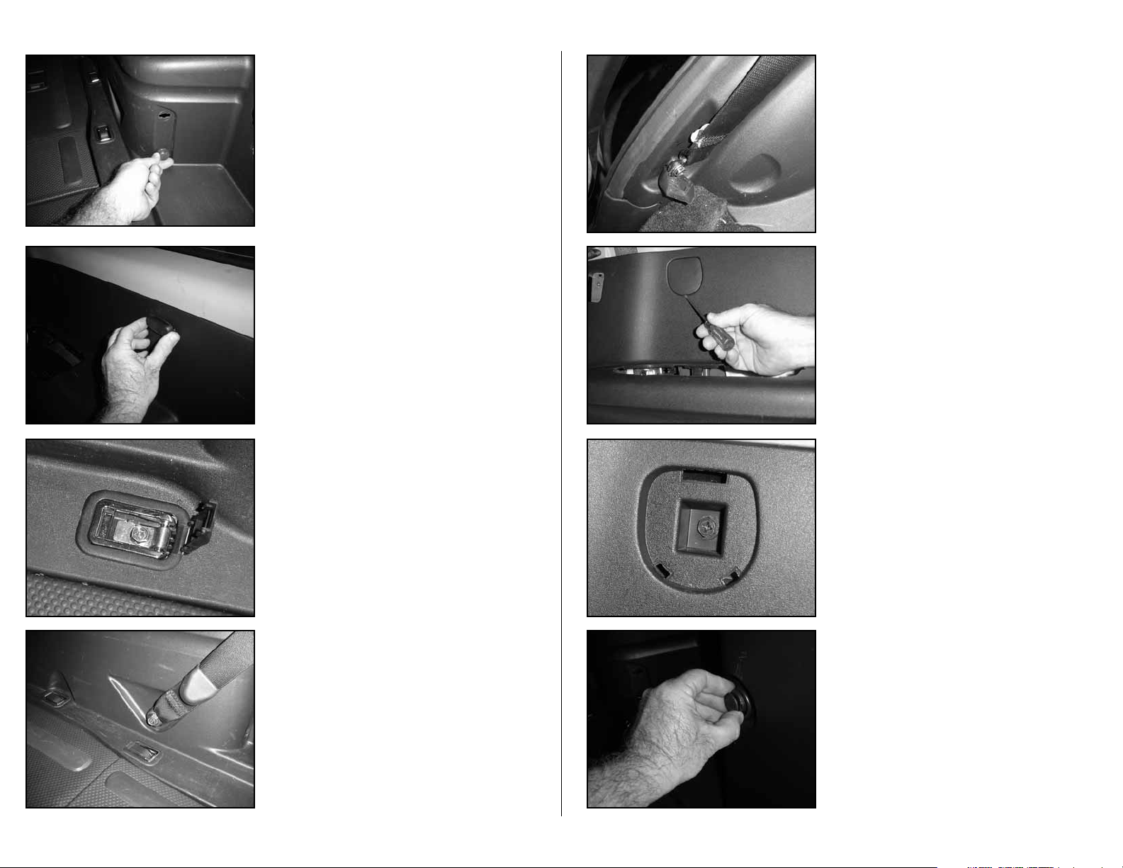
STEP 4
Remove these pair of cargo net hooks.
There are two more of these net ho oks th at are l o cated
across from these on the d-pillar(not pictured).
Grab a hold, twi st and p u l l out from the p anel.
STEP 5
Remove the third row seat belt hold clip.
STEP 6
Remove the three hold down cleats.
STEP 8
Remove the second row seat belt from the side panel.
STEP 9
If the vehicle is equipped with the cargo shade, move to the
next step.
Remove this cover from the side panel. This will expose a
Phillips head bolt.
STEP 10
With a Phillips head screw driver, remove this bolt from the
side panel.
Page 2 • JL Audio, Inc 2007
STEP 7
Remove third row seat belt from the side panel.
STEP 11
Located at the rear most part of the side panel, there is a
cargo net hook. Remove this hook.
To remove this hook, twist and pull from side panel.
Continued on Next Page
Page 3

SB-N-PTHFNDR2/10W3v3_INSTR_SKU#011234
SB-N-PTHFNDR2/10W3v3_INSTR_SKU#011234
STEP 12
Remove the pocket from the side panel.
STEP 13
Unplug the 12v socket and remove the side panel from the
vehicle.
This 12v plug will be covered by the Stealthbox®, once
installed. If this 12v socket is to be used af ter the installation
of the Stealthbox®, you will have to modify the wiring and
remount the socket else where.
STEP 14
The supplied flat bar needs to be mounted into the area that
is pictured. Follow STEPS 15 - 16.
STEP 16
Place a supplied lock washer and flat washer onto a hex bolt.
Place this bolt assembly through the bottom end of the
mounting bar and through the hole in the metal.
Place a flat washer and nut onto the bolt that is exposed
behind the metal. Secure.
STEP 17
Place the side panel back into the vehicle that was removed
in STEP 13.
STEP 18
Mount the cargo net hook that was removed in STEP 11.
Page 3 • JL Audio, Inc 2007
There is a hole in the mounting bar that is off-set to one end
of the flat bar. The short side of the off-set is to be positioned
downward.
The top side of the mounting bar needs to be behind the
wiring harness, see picture.
STEP 15
Place a supplied lock washer and flat washer onto each
hex bolt.
Place each bolt assembly through the holes on the extreme
ends of the flat bar.
Place a flat washer and nut onto the bolt that is exposed on
the backside of the metal, secure.
STEP 19
Secure the bolt that was removed in STEP 10.
Replace the cover that was removed in STEP 9.
Continued on Next Page
Page 4

SB-N-PTHFNDR2/10W3v3_INSTR_SKU#011234
SB-N-PTHFNDR2/10W3v3_INSTR_SKU#011234
STEP 20
Secure the second row seat belt, that was removed in
STEP 8.
STEP 21
Secure the third row seat belt, that was removed in STEP 7.
3.25-inches
4-inches
STEP 23
Place the supplied wax square into place.
Thread in the socket cup set screw into the Stealthbox®,
leaving 1/2-inch exposed.
Place the Stealthbox® in the mounting location, press on it
firmly, against the side panel.
Remove the Stealthbox® carefully, leaving the wax square in
place. The socket cup set screw will leave an impression in
the wax.
Note: Bef ore d r ill i ng , al w ays we a r eye pr ot e c ti on w h en
drilling!
Wit h a drill and a 1/2- i nch dr i l l bit, dril l throu gh the
impressi on made i n the wax squa re and i nto the vehicle ’s
side panel.
The drilled hole in the side panel, should line up with
the hole that i s i n the mou nting bar that was mounted i n
STEP 14-16.
Remove the wax squa re.
STEP 24
Run speaker wire from the amplifier location to the
Stealthbox® location and check for proper operation of
the woofer.
Page 4 • JL Audio, Inc 2007
STEP 22
Secure the three hold down cleats, that was removed in
STEP 6.
STEALTHBOX WALL
THREADED INSERT
VEHICLE SHEET METAL
LOCK WASHER
HEX NUT
SOCKET CUP SET SCREW
FLAT WASHER
FENDER WASHER
STEP 25
Back out the socket cup set screws installed in STEP 23, to
leave 1 1/4-inch of thread exposed.
Place the Stealthbox® into position by guiding the socket cup
set screw through the hole drilled in STEP 23.
Continued on Next Page
Page 5

SB-N-PTHFNDR2/10W3v3_INSTR_SKU#011234
SB-N-PTHFNDR2/10W3v3_INSTR_SKU#011234
JLA-SKU#011234-07-26-200
(2)
3/8-inch -16 x 1-inch Hex Bolt
(1)
3-inch x 3-inch Wax Square
(3)
3/8-inch -16 Hex Nut
(1)
3/8-inch -16 x 2-1/4-inch Socket Cup Set Screw
(3)
3/8-inch Split Lock Washer
(1)
16.0-inch x 1.5-inch x 0.25-inch Flat bar
(5)
3/8-inch Flat Washer
Acoustic Suspension (sealed)
10W3v3-4
4 ohms mono
300 Watts
6-inch x 9-inch / Front Doors
TR690-TXi & VR690-CXi
6.5-inch / Rear Doors
TR650-CXi, TR650-CSi, VR650-CXi, VR650-CSi,
XR650-CXi, XR650-CSi, C5-650x,C5-650 & ZR650-CSi
STEP 26
To place the supplied mounting assembly onto the socket
cup set screw, you need to reach through the opening of the
removed pocket from STEP 12.
Place the supplied flat washer, lock washer and then hex
nut onto the socket cup set screw. Secure the mounting
assembly.
Replace the removed pocket.
STEP 27
Replace the tailgate’s bottom sill plate, from STEP 2.
STEP 28
Replace the cargo area f looring, from STEP 1.
INCLUDED HARDWARE
(2)
3/8-inch -16 x 1-inch Hex Bolt
(3)
3/8-inch -16 Hex Nut
(3)
3/8-inch Split Lock Washer
(5)
3/8-inch Flat Washer
(1)
3-inch x 3-inch Wax Square
(1)
3/8-inch -16 x 2-1/4-inch Socket Cup Set Screw
(1)
16.0-inch x 1.5-inch x 0.25-inch Flat bar
SPECIFICATIONS
Enclosure Type:
Driver Type:
Nominal Impedance:
Continuous Power Handling:
Acoustic Suspension (sealed)
10W 3v3- 4
4 ohms mono
300 Watts
POWER RECOMMENDATION
JL Audio recommends using a high quality amplifier such as the JL Audio 250/1v2.
The diagram below shows the recommended crossover, infrasonic filter and equalizer settings for the 250/1v2
when being used to power your Stealthbox®.
The JL Audio 250/1v2 is a very versatile audio component. Please consult the owner’s manual for even more
detailed information about installing and tuning this amplifier.
Page 5 • JL Audio, Inc 2007
CONGRATULATIONS
You have completed the installation for this model!
Please refer to the Power Recommendation section for an
amplifier recommendation and basic set-up help.
MID/HIGH FREQUENCY DRIVER FITMENT
A variety of JL Audio coaxial and component systems will fit in the factory speaker locations of you vehicle.
Front Speaker Size / Location:
Fits JL Audio Models:
Rear Speaker Size / Location:
Fits JL Audio Models:
XR650-CXi, XR650 -CSi, C5-650x,C5-650 & ZR650-CSi
All specifications are subject to change without notice. “JL Audio®” and the JL Audio logo, “Stealthbox” and the Stealthbox logo are registered
trademarks of JL Audio, Inc. “Ahead of the Curve” and its respective logo is a trademark of JL Audio, Inc.
JLA-SKU#011234-07-26-20077 • Printed in USA • ©2005 JL Audio, Inc. • U.S. PATENTS: #5,734,734 #5,949,898 #6,118,884 #6,229,902
#6,243,479 #6,294,959 #6,501,844 #6,496,590 #6,441,685 #5,687,247 #6,219,431 #6,625,292 #D472,891 #D480,709 Other U.S. & Foreign
patents pending. For more detailed information please visit us online at www.jlaudio.com.
10369 NORTH COMMERCE PARKWAY • MIRAMAR, FLORIDA • 33025 • USA
6-inch x 9-inch / Front Doors
TR690 -TXi & VR690-CXi
6.5-inch / Rear Doors
TR650-CXi, TR650-CSi, VR650-CXi, VR650-CSi,
(954) 443-1100
www.jlaudio.com
 Loading...