

Page 1
INSTALLATION GUIDE
SB-N-FRNTCC/10W1v2
2005 - Up
Nissan Frontier CrewCab Trucks
SB-N-FRNTCC/10W1v2_INSTR_SKU#011229
2
for the
SB-N-FRNTCC/10W1v2
2005 - Up
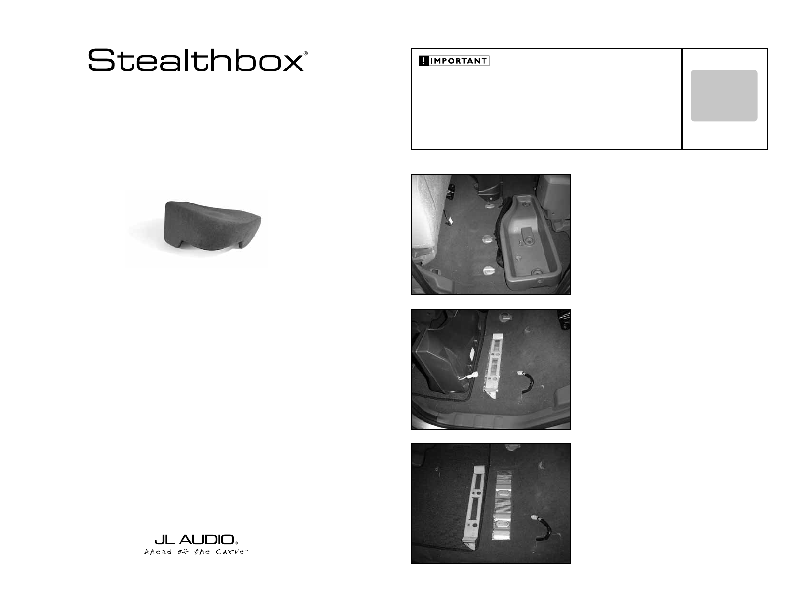
Thank you for choosing a JL Audio Stealthbox® for your automotive sound system. With proper
installation, your new vehicle-specific enclosed subwoofer system will deliver years of listening pleasure.
Nissan Frontier CrewCab Trucks
SB-N-FRNTCC/10W1v2_INSTR_SKU#011229
If you choose to perform the installation yourself, it is absolutely vital that
the Stealthbox
instructions. Failure to mount the enclosure properly presents two problems:
1) The sub-bass performance will suffer due to the movement of the enclosure
caused by the force exerted by the woofer(s).
2) A loose enclosure presents a serious safety hazard in the event of a collision
or sudden deceleration.
®
be properly mounted to the vehicle according to these
STEP 1
Remove both storage bins from under the rear seat.
If the truck is not equipped with the factory woofer, go to
STEP 4.
STEP 2
Using a 10mm socket, remove the three mounting bolts that
secure the factory woofer enclosure to the truck’s floor.
INSTALLATION
DIFFICULTY:
OUT
OF
5
ESTIMATED TIME:
1 HOUR
We strongly recommend that you have your new Stealthbox® installed by your authorized JL Audio
dealer. The installation professionals employed by your dealer have the necessary tools and experience
to disassemble and reassemble your vehicle properly. Also, keep in mind that your warranty coverage
extends to 1 year if your system is installed or approved by your authorized JL Audio dealer. If you
prefer to perform your own installation, please read this installation guide completely
before beginning the process.
STEP 3
Using a 10mm socket, remove the two mounting bolts that
secure this mounting bracket to the truck’s floor.
Tuck the factory speaker wire under the carpet and out of
the mounting area of the Stealthbox®.
Continued on Next Page
Page 2
SB-N-FRNTCC/10W1v2_INSTR_SKU#011229
SB-N-FRNTCC/10W1v2_INSTR_SKU#011229
5-inches
6-inches
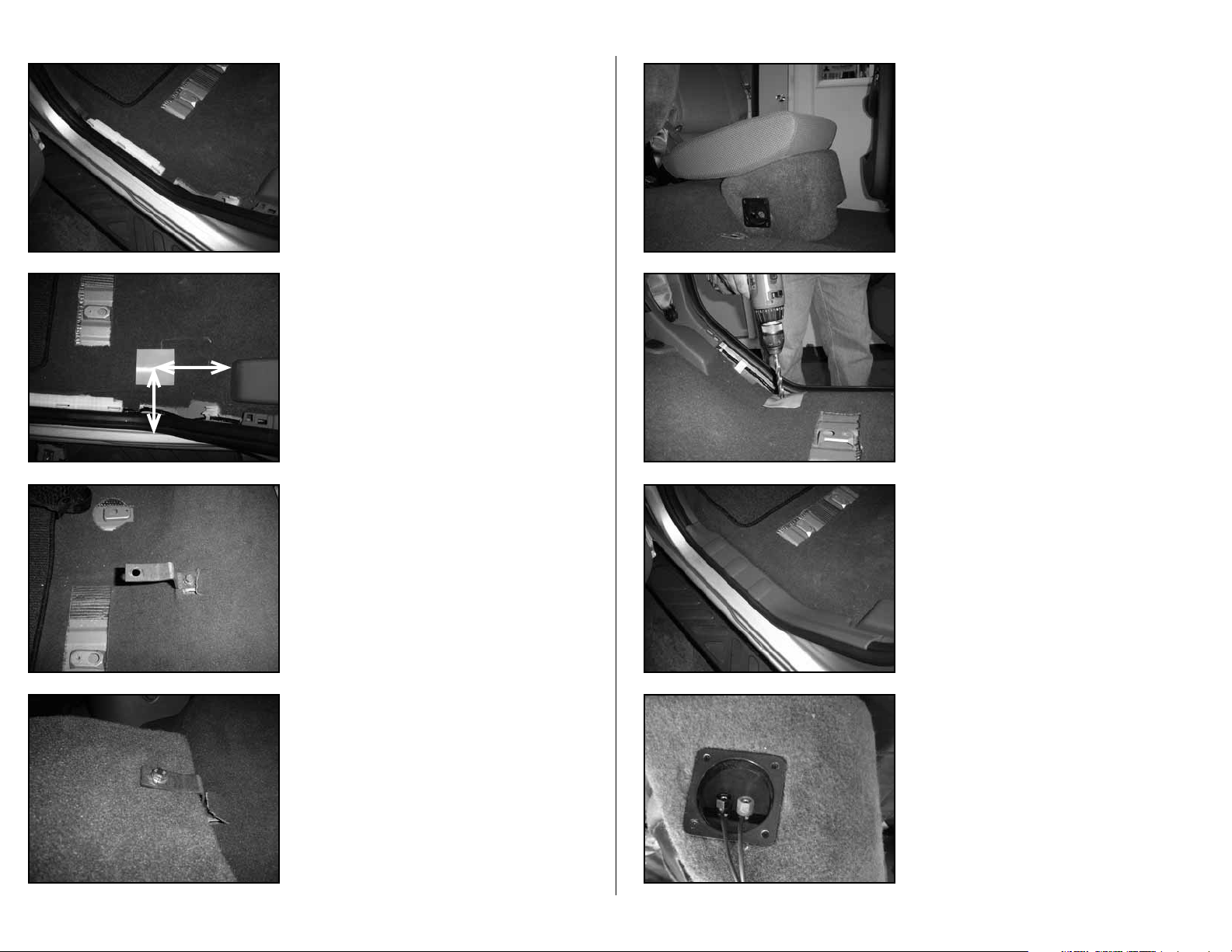
STEP 4
Remove the sill plate.
STEP 5
Place the middle of the wax square into place, shown in the
picture.
STEP 6
Trucks that are equipped with the factory woofer.
Use the supplied 6mm bolt to secure the short end of the
supplied Z-bracket to the floor, as in the picture. Only hand
tighten at this time.
STEP 8
Lower the seat d o wn onto the Stealth b ox
®
. Line u p the top
corn er of the St ealt h box® to the bottom corner of the seat.
Flip t h e seat up and push down on t o the top of t he
Stealthbox
®.
Unbo lt the Z-br acket and rem ov e the Stealth box® carefully,
leavi n g the wax squa re in pla ce. The s o cket cup s et scre w
will leave an impression in the wax.
Using an util ity knife , c ut an “X” thr o ugh the wax sq uare a t
the im pression of the socke t c up set sc rew and t hrough the
carpet.
STEP 10
Note: Bef or e dr il li n g, m a ke su re t h at yo u ar e no t go in g
to be drilling into any gas lines, brake lines, transmission
lines, electrical wiring, transfer case (4x4 vehicles)
or anyt hi ng e l se t h at m ig h t c au se a re d uc t i on i n you r
weekly pay. Always wear eye protection when drilling!
Wit h a 1/2-inc h dril l b it and d rill, place th e drill bit th rough
wax s quare and the carpetin g at the im pression made in
the wax square. Dril l through the m etal floor. Remove th e
wax square.
STEP 11
Place the sill plate back into place.
Page 2 • JL Audio, Inc 2006
Trucks that are not equipped with the factory woofer.
Feel for a mounting point that is located under the carpet
and on the floor area that slopes up. Once found, cut the carpet around this mounting point. Use the supplied 6mm bolt
to secure the short end of the supplied Z-bracket to the floor.
Only hand tighten at this time.
STEP 7
Place the Stealthbox® into the mounting location.
Use a supplied 3/8-inch bolt to secure the long end of the
Z-bracket to the top of the Stealthbox®. Only hand tighten at
this time.
STEP 12
Place the Stealthbox® into the mounting area.
Run speaker wire to the Stealthbox® and wire to the terminal.
Double check the woofer for proper operation.
Back out the socket cup set screw to expose 2-inches
®
Place t h e S tealthbox
into position by guiding the socket
cup set screw t hrough the drille d hole.
Continued on Next Page
Page 3

SB-N-FRNTCC/10W1v2_INSTR_SKU#011229
SB-N-FRNTCC/10W1v2_INSTR_SKU#011229
JLA-SKU#011229-05-12-200
(2)
Black Rubber Tapered Squares
(1)
3/8-inch -16 x 1 1/2-inch Bolt
(2)
3/8-inch Split Lock Washer
(1)
3/8-inch x 1 1/4-inch Fender Washer
(2)
3/8-inch Flat Washer
(1)
Z-Bracket
(1)
6mm x16mm Bolt
(1)
3-inch x 3-inch Wax Square
(1) 3/8-inch -16 Hex Nut
(1)
3/8-inch -16 x 2 1/4-inch Socket Cup Set Screw
(1)
6mm Flat Washer
Acoustic Suspension (sealed)
10W1v2-4
4 ohms mono
150 Watts
6.5-inch / Front Doors
TR650-CXi, TR650-CSi, VR650-CXi, VR650-CSi, XR650-CXi, XR650-CSi,
C5-650x, C5-650 & ZR650-CSi
6.5-inch / Rear Doors
TR650-CXi, TR650-CSi, VR650-CXi, VR650-CSi, XR650-CXi, XR650-CSi,
C5-650x, C5-650 & ZR650-CSi
STEALTHBOX WALL
FENDER WASHER
FLAT WASHER
LOCK WASHER
HEX NUT
THREADED INSERT
VEHICLE SHEET METAL
SOCKET CUP SET SCREW
STEP 13
Place a supplied 3/8-inch lock washer and flat washer onto
the 3/8-inch bolt.
Place the supplied 6 mm flat wa sher onto the 6mm bolt.
Using a socket, fully secure the Z-bracket to the truck’s
moun ting point and on top of the Stealthbox®.
STEP 14
From under the vehicle, place a supplied fender washer,
flat washer, lock washer and then hex nut onto the socket
cup set screw and secure.
Note: For adde d p rot e c ti o n it i s re co mm e nd ed t h at
you appl y a be ad o f si li co ne b e t we e n t he ve hi c le a nd
the fen de r w a sh e r. Aft e r th e b ol t a ss e mb l y is t i gh t ly
secured, it is also recomme nded th at vehicle und ercoatin g m at e ri a l is a p pl ie d t o t he e x po se d a ss e mb l y
STEP 15
Secure the passenger’s side storage bin.
INCLUDED HARDWARE
(2)
Black Rubber Tapered Squares
(2)
3/8-inch Split Lock Washer
(2)
3/8-inch Flat Washer
(1)
6mm x16mm Bolt
(1) 3/8-inch -16 Hex Nut
(1)
6mm Flat Washer
(1)
3/8-inch -16 x 1 1/2-inch Bolt
(1)
3/8-inch x 1 1/4-inch Fender Washer
(1)
Z-Br ack et
(1)
3-inch x 3-inch Wax Square
(1)
3/8-inch -16 x 2 1/4-inch Socket Cup Set Screw
SPECIFICATIONS
Enclosure Type:
Driver Type:
Nominal Impedance:
Continuous Power Handling:
Acoustic Suspension (sealed)
10W1v2 -4
4 ohms mono
150 Wa t ts
POWER RECOMMENDATION
JL Audio recommends using a high quality amplifier such as the JL Audio A2150.
The diagram below shows the recommended crossover, infrasonic filter and equalizer settings for the A2150 when
being used to power your Stealthbox®.
Page 3 • JL Audio, Inc 2006
CONGRATULATIONS
You have completed the installation for this model!
Please refer to the Power Recommendation section for an
amplifier recommendation and basic set-up help.
The JL Audio A2150 is a very versatile audio component. Please consult the owner’s manual for even more
detailed information about installing and tuning this amplifier.
MID/HIGH FREQUENCY DRIVER FITMENT
A variety of JL Audio coaxial and component systems will fit in the factory speaker locations of you vehicle.
Front Speaker Size / Location:
Fits JL Audio Models:
C5-650x, C5-650 & ZR650-CSi
TR650-CXi, TR650-CSi, VR650-CXi, VR650-CSi, XR650-CXi, XR650-CSi,
Rear Speaker Size / Location:
Fits JL Audio Models:
C5-650x, C5-650 & ZR650-CSi
All specifications are subject to change without notice. “JL Audio®” and the JL Audio logo, “Stealthbox” and the Stealthbox logo are registered
trademarks of JL Audio, Inc. “Ahead of the Curve” and its respective logo is a trademark of JL Audio, Inc.
JLA-SKU#011229-05-12-20077 • Printed in USA • ©2005 JL Audio, Inc. • U.S. PATENTS: #5,734,734 #5,949,898 #6,118,884 #6,229,902
#6,243,479 #6,294,959 #6,501,844 #6,496,590 #6,441,685 #5,687,247 #6,219,431 #6,625,292 #D472,891 #D480,709 Other U.S. & Foreign
patents pending. For more detailed information please visit us online at www.jlaudio.com.
10369 NORTH COMMERCE PARKWAY • MIRAMAR, FLORIDA • 33025 • USA
6.5-inch / Front Doors
6.5-inch / Rear Doors
TR650-CXi, TR650-CSi, VR650-CXi, VR650-CSi, XR650-CXi, XR650-CSi,
(954) 443-1100
www.jlaudio.com
 Loading...