

Page 1
➔
➔
➔
➔
Stealthbox
®
INSTALLATION GUIDE
SB-N-350/10W3v2, JL AUDIO, Inc 2004
Sheet SKU#011187 Revision 2/11/2004Page 1
for the
SB-N-350/10W3v2
(2003-Up 350Z, Will not fit the 350z
Roadster, Infiniti G35 Coupe & Sedans)
This Stealthbox is a product which
requires professional installation skills and
tools.
Please read this installation guide thoroughly before beginning the project. It
will guide you step by step through the
installation. Several of the steps in this
process may require two people to
accomplish.
It is absolutely vital that the enclosure
be properly mounted to the vehicle
according to these instructions. Failure
to mount the enclosure properly presents two problems: 1) The sub-bass
performance will suffer due to the
movement of the enclosure caused by
the force exerted by the woofer(s) and
2) A loose enclosure presents a serious
safety hazard in the event of a collision
or sudden deceleration.
Please enjoy your JL Audio Stealthbox
responsibly.
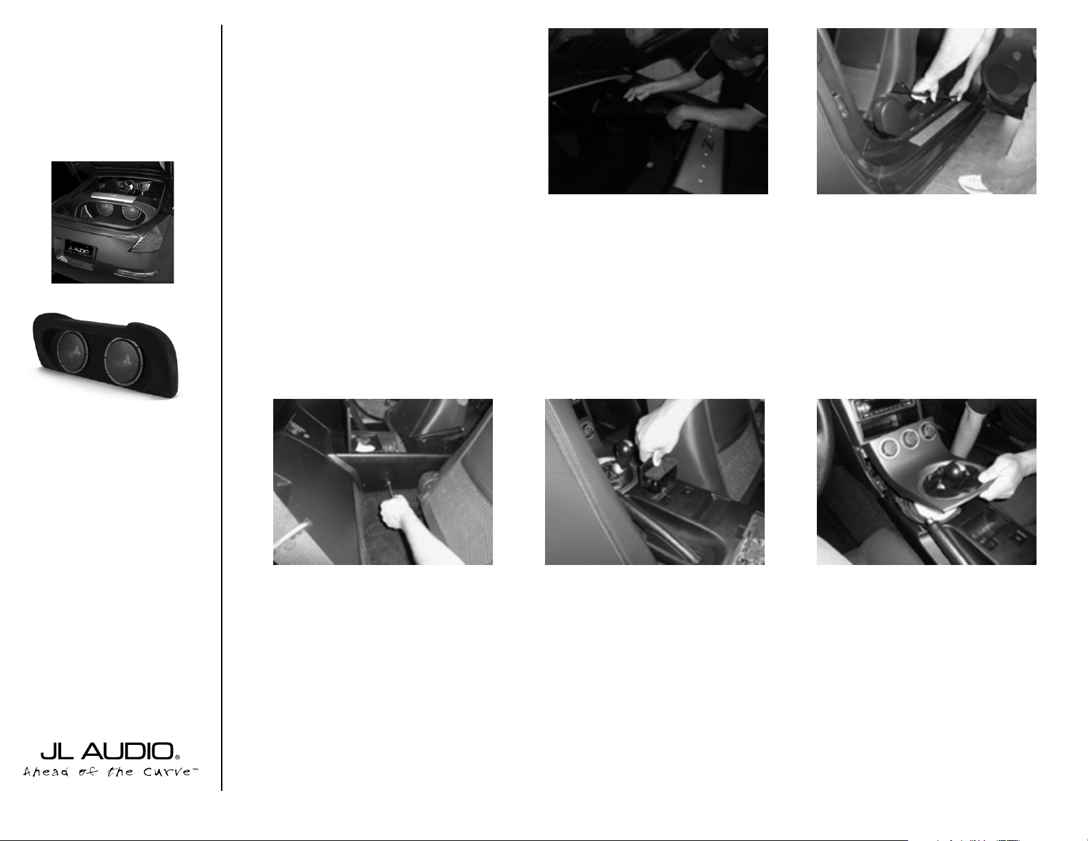
STEP 1:
Remove all contents from center
console, rear cargo area, rear glove box compartments, lastly slide and tilt the seats to the
front of the car.
STEP 3:
Remove the driver’s side and pas-
senger’s side door sill panels.
*Carefully pulling directly upward.*
STEP 2:
Remove the driver’s side and passenger’s side rear interior cargo quarter panels.
STEP 4:
Remove the Philip head screws, that
are found on both diver’s side and passenger’s side of the console.
STEP 5:
Remove the two Philip head screws
that have been exposed by the removal of
the ashtray.
START
HERE
Continued on Next Page ➔
www.jlaudio.com
➔
➔
STEP 6: Loosen the shifter trim panel by pulling
directly up. Pull the panel away from the console.
Manual transmission shifter shown in picture, automatic shifter removal maybe slightly different, then
shown.
*Careful not to damage the shifter or
scratch the dash panel. *
Page 2
➔➔
➔➔➔
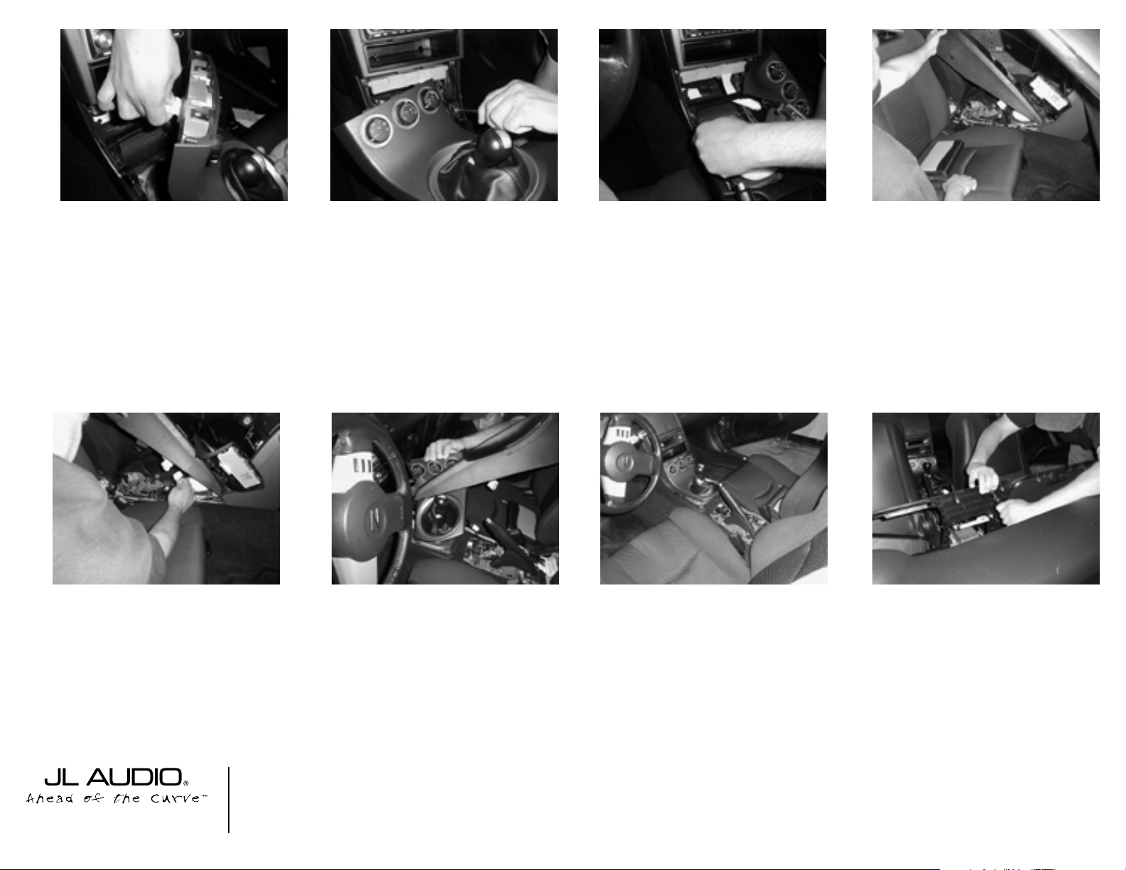
STEP 10: Lift at the rear of the console and carefully pull unit over the emergency hand brake arm.
Cont.
From
Previous
Page
Continued on Next Page ➔
➔
STEP 7: Disconnect the white wiring plug at the
rear of the A/C controls.
STEP 11: Disconnect the wiring harness at the
plug located under the center console.
➔
STEP 12: Carefully guide the shifter boot trim
panel through the front opening in the console.This
will allow for full removal of the center console.
*Careful not to damage the shifter boot or
scratch the dash panel. *
STEP 13: Remove the center console, out of the
vehcile.
STEP 8: With the shifter trim panel moved to
one side. Remove the pair of Philip head screws at
the front edge of the console.
STEP 9: Engage the emergency brake, by pulling
up on the handle.
SB-N-350/10W3v2, JL AUDIO, Inc 2004
Sheet SKU#011187 Revision 2/11/2004Pag e 2
www.jlaudio.com
STEP 14: Remove the rear bulkhead front panel,
by carefully pulling towards the front of the vehcile
around the glove box.
Page 3

➔➔
➔➔
➔
STEP 18: Pull back the carpet in the front section
of the cargo area to reveal the metal floor.
Remove the child seat anchor hooks, reinstall factory
bolts without hook.
Locate the existing holes(behind the driver’s side
and passenger’s side seat), to be used to mount the
Stealthbox. Identified by the white circle.
Cont.
From
Previous
Page
Continued on Next Page ➔
➔
STEP 16: Remove the pair of 10mm head bolts at
the rear of the glove box.
STEP 19: Cut the carpet to create a flap that can
be folded to allow access to the mounting holes.
➔
STEP 20: If the vehicle is so equipped, fold back
floor mat as shown to access the mounting bolts.
STEP 22: At this time, attach the speaker wire
from the amp to the Stealthbox’s terminal.
*Check for proper operation of the
woofers.*
STEP 17: Remove the numerous 10mm head
bolts securing the front edge of the glove box liner.
SB-N-350/10W3v2, JL AUDIO, Inc 2004
Sheet SKU#011187 Revision 2/11/2004 Page 3
www.jlaudio.com
STEP 15:
Remove the pair of Philip head
screws securing the passenger side glove box’s
door latch.
Repeat this STEP for the driver’s side, if
equipped with the glove box. Remove the factory woofer on the driver’s side, if equipped.
STEP 21: Thread in the supplied pair of socket
cup set screws. Leaving about 1.5” exposed.
➔
➔
➔
Page 4

Specifications:
Enclosure Type: Acoustical Suspension(Sealed)
Driver Type: 2) 10W3v2-D4
Nominal Impedance: 4Ω
Cont. Power Handling: 600Watts
JL Audio recommends using a high quality amplifier such as the JL Audio 500/1. The diagram below shows the recommended
crossover, infrasonic filter and equalizer settings for the 500/1 when being used to power your Stealthbox®.
Included Hardware:
2) 3/8” Split Lock Washers
2) 3/8” Flat Washers
2) 3/8” x 1-1/4” Fender Washers
2) 3/8”x 2-/1/4” Socket Cup Set Screws
2) 3/8” Hex Nuts
10369 N. Commerce Pkwy, Miramar, Florida 33025-392 Phone: 954.443.1100 Fax: 954.443.1111
The JL Audio 500/1 is a very versatile audio component. Please consult the owner’s manual for detailed information
about installing and tuning this amplifier.
➔➔➔
STEP 24: Set the Stealthbox into position in the
vehicle. Placing the socket cup set screws through the
cut carpet and existing holes from STEP19 & 20.
Route the woofers’ wiring behind the enclosure to
the large hole at the far end of the passenger side
cargo area. Identified by the white circle.
Route the wiring down through this hole to the glove
box cavity for the connection to an amplifier.
STEP 25: The socket cup set screws are protruding
into the glove box/factory woofer area. Place the supplied fender washer, lock washer and hex nut onto
each socket cup set screws. Indentified by the black circle in STEP 24.
If needed, expose more length of the socket cup set
screws. Secure tightly.
*Make sure the Stealthbox is centered with
the strut tower brace.*
STEP 26: Reassemble the vehicle’s panels in
reverse order of disassembly.
➔
SB-N-350/10W3v2, JL AUDIO, Inc 2004
Sheet SKU#011187 Revision 2/11/2004 Page 4
www.jlaudio.com
Mid/High Frequency Driver Information:
CONGRATULATIONS!
INSTALL COMPLETE.
XR650-CSi
VR650-CXi
Front Location Driver Size:
6.5”
Applicable JL Audio Products:
XR,VR & TR650-CSi
Rear Location Driver Size:
6.5”
Applicable JL Audio Products:
XR,VR & TR650-CXi
Cont.
From
Previous
Page
➔
➔
 Loading...