

Page 1
SB-J-UNLTD4DR/13TW5 INSTR_SKU# 011276
I N S T A L L A T I O N G U I D E
for the
SB-J-UNLTD4DR/13TW5-3
SKU#94418
2007+
Thank you for choosing a JL Audio Stealthbox® for your automotive sound system. With proper
installation, your new vehicle-specific enclosed subwoofer system will deliver years of listening pleasure.
We strongly recommend that you have your new Stealthbox® installed by your authorized JL Audio
dealer. The installation professionals employed by your dealer have the necessary tools and experience
to disassemble and reassemble your vehicle properly. If you prefer to perform your own installation,
please read this installation guide completely
before beginning the process.
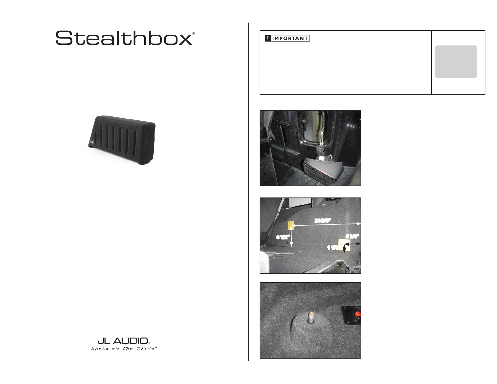
If you choose to perform the installation yourself, it is absolutely vital that
the Stealthbox® be properly mounted to the vehicle according to these
instructions. Failure to mount the enclosure properly presents two problems:
1) The sub-bass performance will suffer due to the movement of the enclosure
caused by the force exerted by the woofer(s).
2) A loose enclosure presents a serious safety hazard in the event of a collision
or sudden deceleration.
6 1/2”
24 3/4”
S T E P 1
Empty the passengers side rear of the Jeep, remove the 4
screws that secure the tail-light. Unplug the light assembly
and set it aside as you’ll need access into the area behind
where it was mounted.
S T E P 2
Place the two wax squares on the inner fender as shown in
the picture (left) measuring from the outside edge of the
tailgate opening forward and, up from the floor.
6 1/4”
1 1/4”
INSTALLATION
D I F F I C UL T Y:
OU T
OF
35
ESTIMATED TIME:
23 HOURS
S T E P 3
Thread the 3/8”- 16 studs into the enclosures so that only
3/8” projects from the bosses. Now is also a good time to
verify the performance of the woofer before it’s mounted.
Continued on Next Page
Page 2
SB-J-UNLTD4DR/13TW5 INSTR_SKU# 011276
THREADED INSERT
CARPETING
LOCK WASHER
FLAT WASHER
STEALTHBOX WALL
HEX NUT
VEHICLE SHEET METAL
ALLEN HEAD STUD
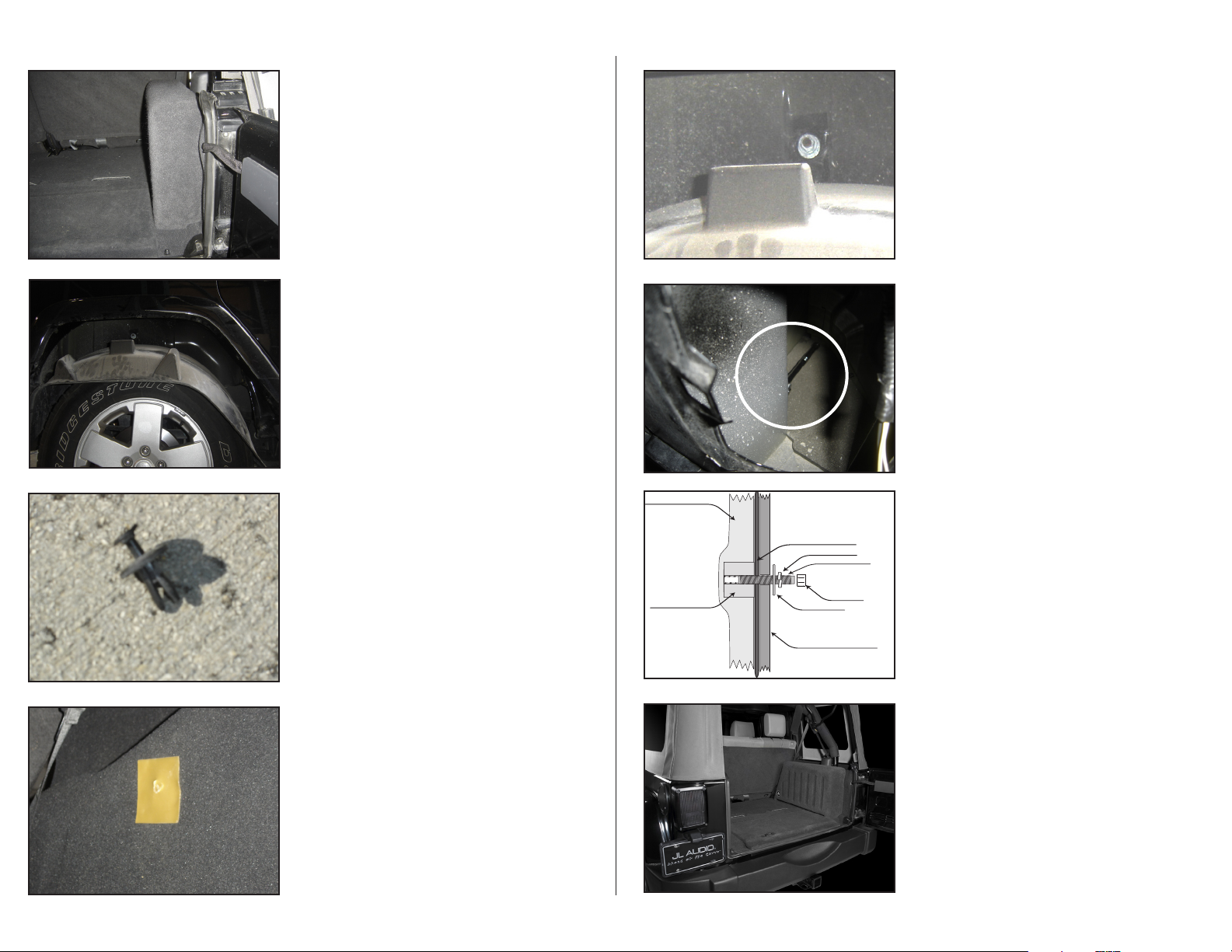
S T E P 4
Slide enclosure into place and press against the inner fender,
producing indentations in the wax squares where the studs
hit. Remove the enclosure.
S T E P 5
Notice the Inner Fender Liner Fasteners, all 12 of these fasteners need to be removed so that the Inner Fender Liner can
be dropped down on the rear tire. This needs to be done so
that you can gain access to the Hole where the Allen Head
Stud will come through the Inner Fender.
D E T A I L
Pulling on the center head of the inner fender body fasteners
will allow the fastener to be removed. Re-installation is the
reverse process, push the body of the fastener through the
holes then, push the center head in to expand the body.
S T E P 7
Start the included hardware on the 3/8-16 Allen Head Stud.
There should be a 3/8x 1-1/2” Fender Washer, Split lock
Washer and Hex Nut on the Allen Head Stud. (see
illustration at STEP 9 for details).
S T E P 8
Reaching down and around through the hole where the
taillight mounts, you will find the rear Allen Head Stud.
Install included hardware as illustrated above. Re-install
the previously removed Taillight, test the operation of the
taillights.
S T E P 9
Once the hardware is started on BOTH the front, and rear
Allen Head Studs, you can tighten the hardware down.
Page 2 • JL Audio, Inc 2008
S T E P 6
At each mark in the wax squares, drill a 3/8” hole through the
carpeting and inner fender. Back out the Allen Head Studs in
the Stealthbox® so that Approximately 1” is exposed.
*CAUTION*
Before drilling, always make sure that you are not
going to be drilling into any gas lines, brake lines,
transmission lines, electrical wiring, exhaust systems
or anything else that might cause a reduction in
your weekly pay. Always wear eye protection when
drilling.
S T E P 1 0
C O N G R A T U L A T I O N S !
You have completed the installation for this model!
Enjoy your new Stealthbox®!
Please refer to the Power Recommendation section for an
amplifier recommendation and basic set-up help.
Continued on Next Page
Page 3

SB-J-UNLTD4DR/13TW5 INSTR_SKU# 011276
I N C L U D E D H A R D W A R E
2) 3”X 3” Wax Square 2) 3/8-16 x 2-1/4” Allen Head Stud
2) 3/8” x 1-1/4” Fender Washer 2) 3/8” Flat Washer
2) 3/8” Split Lock Washer 2) 3/8-16 Hex Nut
S P E C I F I C A T I O N S
Enclosure Type: Acoustic Suspension (sealed)
Driver Type: 13TW5-3
Nominal Impedance: 3 Ohms
Continuous Power Handling: 600 Watts RMS
P O W E R R E C O M M E N D A T I O N
JL Audio recommends using a high quality amplifier such as the JL Audio 250/1v2.
The diagram below shows the recommended crossover, infrasonic filter and equalizer settings for the 250/1v2
when being used to power your Stealthbox®.
The JL Audio 250/1v2 is a very versatile audio component. Please consult the owner’s manual for even more
detailed information about installing and tuning this amplifier.
Page 5• JL Audio, Inc 2008
M I D / H I G H F R E Q U E N C Y D R I V E R F I T M E N T
A variety of JL Audio coaxial and component systems will fit in the factory speaker locations of you vehicle.
Front Speaker Size / Location: 6 3/4-inch/ Dash
Fits JL Audio Models: TR650-CSi, TR650-CXi, VR650-CSi, VR650-CXi, XR650-CSi, XR650-CXi,
C5-650, C5-650x & ZR650-CSi
Rear Speaker Size / Location: 6 3/4-inch / Roll Bar (Custom Mounting Plate Required)
Fits JL Audio Models: TR650-CSi, TR650-CXi, VR650-CSi, VR650-CXi,
XR650-CSi, XR650-CXi, C5-650, C5-650x & ZR650-CSi
(954) 443-1100
All specifications are subject to change without notice. “JL Audio®” and the JL Audio logo, “Stealthbox” and the Stealthbox logo are registered
trademarks of JL Audio, Inc. “Ahead of the Curve” and its respective logo is a trademark of JL Audio, Inc.
JLA-SKU# 011276 10-7-2008 • Printed in USA • ©2008 JL Audio, Inc. • U.S. PATENTS: #5,734,734 #5,949,898 #6,118,884 #6,229,902 #6,243,479
#6,294,959 #6,501,844 #6,496,590 #6,441,685 #5,687,247 #6,219,431 #6,625,292 #D472,891 #D480,709 Other U.S. & Foreign patents pending.
For more detailed information please visit us online at www.jlaudio.com.
1 0 3 6 9 N O R T H C O M M E R C E P A R K W A Y • M I R A M A R , F L O R I D A • 3 3 0 2 5 • U S A
w w w. j l a u d i o . c o m
 Loading...