

JL Audio SB-J-JL4DDRV/10TW1-2, SB-J-JL4DDRV/10TW1-4, SB-J-JL4DPAS/10TW1-2, SB-J-JL4DPAS/10TW1-4 Stealthbox Installation Guide

SB-J-JL4DDRV/10TW1 & SB-J-JL4DPAS/10TW1 INSTR_SKU# 011510
If you choose to perform the installation yourself, it is absolutely
vital that the Stealthbox
according to these instructions. Failure to mount the enclosure
properly presents two problems:
1) The sub-bass performance will suffer due to the movement of the
enclosure caused by the force exerted by the woofer(s).
2) A loose enclosure presents a serious safety hazard in the event of a
collision or sudden deceleration.
®
be properly mounted to the vehicle
INSTALLATION
DI FFICU LTY:
OUT
OF
5
4
ESTIMATED TIME:
23 HOURS
INSTALLATION GUIDE
for the
SB-J-JL4DDRV/10TW1-2
SB-J-JL4DDRV/10TW1-4
SKU# 94664 (2 W) & 94665 (4 W)
SB-J-JL4DPAS/10TW1-2
SB-J-JL4DPAS/10TW1-4
SKU# 94666 (2 W) & 94667 (4 W)
2018-Up Jeep Wrangler (JL) 4-Door
Enclosure Type: Sealed
Driver Type: 10TW1
Nominal Impedance: 2 or 4 ohms
Continuous Power Handling: 300 watts (RMS method)
Thank you for choosing a JL Audio Stealthbox® for your automotive sound system.
With proper installation, your new vehicle-specific enclosed subwoofer system
will deliver years of listening pleasure.
We strongly recommend that you have your new Stealthbox® installed by your
authorized JL Audio dealer. The installation professionals employed by your
dealer have the necessary tools and experience to disassemble and reassemble
your vehicle properly. If you prefer to perform your own installation, please read
this installation guide completely before beginning the process.
Continued on Next Page
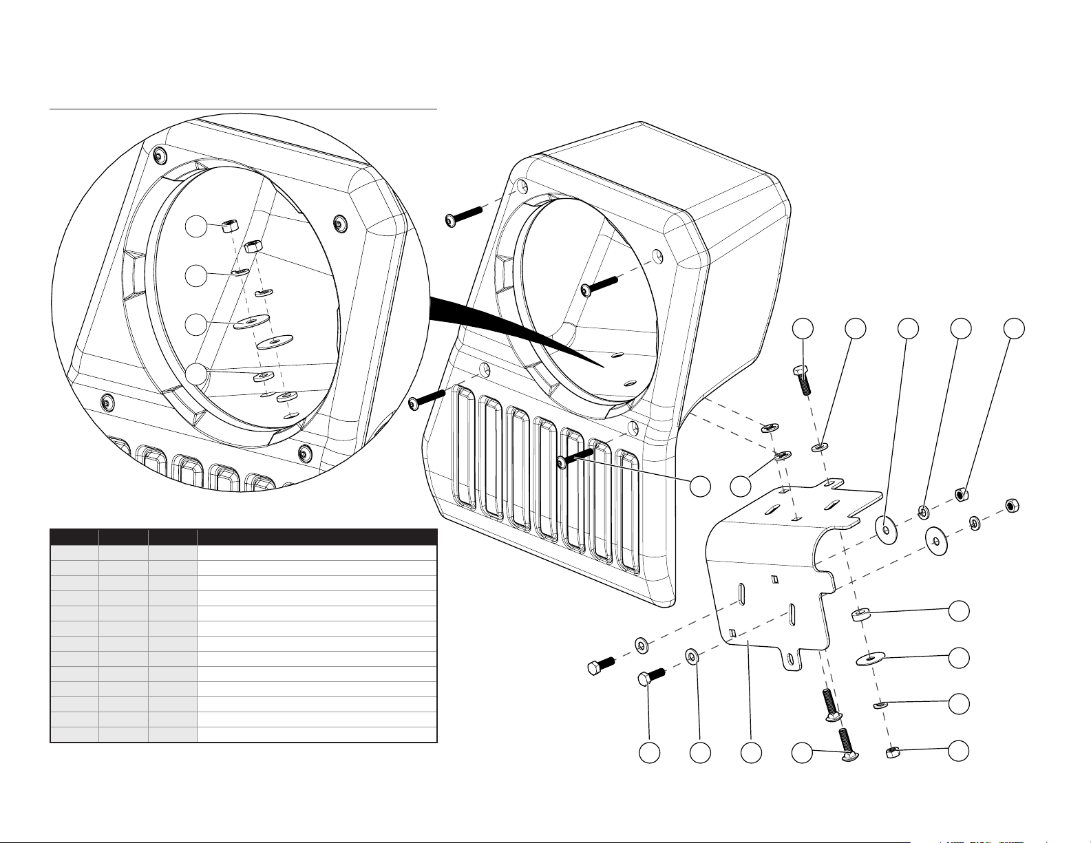
INCLUDED HARDWARE
BOM ID Qty SKU Description
- 8 153999 1/4” x 2-3/16” Nylon Expansion Rivet (not shown)
SB-J-JL4DDRV/10TW1 & SB-J-JL4DPAS/10TW1 INSTR_SKU# 011510
1
2
3
4
1 5 153998 5/16 - 18 Hex Nut
2 5 150929
3 5 153997 5/16” Oversized Flat Washer
4 2 153991 5/16” Rubber Sealing Washer
5 3 153994 5/16 - 18 x 1” Hex Head Bolt
6 3 153995 5/16” Flat Washer
7 4 153996 M6 x 45mm Socket Flanged Button Screw
8 2 153992 5/16” Retaining Washer
9 1 153776 1/4” Aluminum Spacer
10 1 153976 Mounting Bracket
11 2 153990 5/16 - 18 x 1-1/4” Square Neck Carriage Bolt
- 8 154000 Fender Shield Retainer Clip (not shown)
5/16” Split Lock Washer
5
8
7
6
123
9
3
2
Page 2 • JL Audio, Inc., 2018
65
10
11
1
Continued on Next Page
SB-J-JL4DDRV/10TW1 & SB-J-JL4DPAS/10TW1 INSTR_SKU# 011510
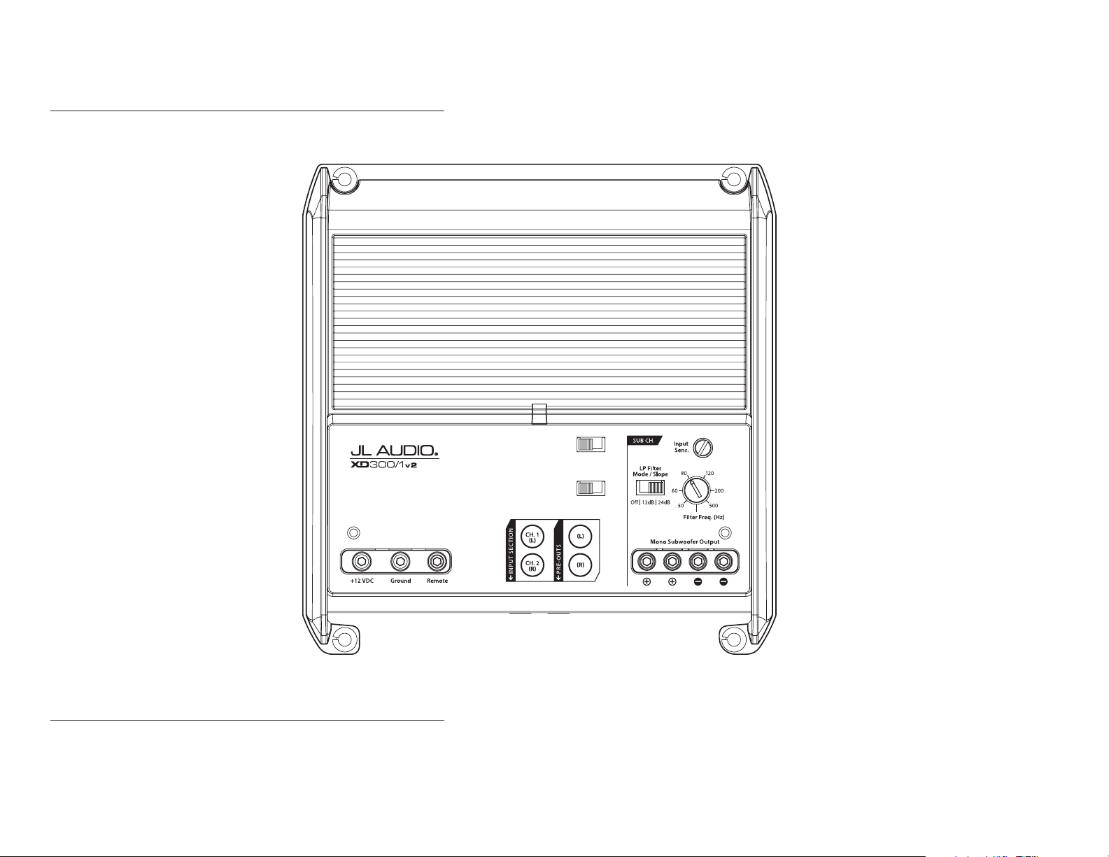
POWER RECOMMENDATION
JL Audio recommends high quality ampliers such as the JL Audio XD300/1v2. The diagram below shows the recommended crossover settings for the XD300/1v2. For a detailed description of the
amplier settings, consult the owner’s manual for the amplier. If another amplier is being used, please reference this illustration and use similar settings on that amplier.
Turn-On Mode
Rem. | Oset | Signal
Monoblock Subwoofer Amplifier
Input Voltage
Low | High
CONNECTIONS
Using quality power, signal, and speaker wire is essential in ensuring the performance of your Stealthbox®. JL Audio recommends using a 4 AWG power kit such as the XD-PCS4-1B for your
Stealthbox® amplier. Other kits are available should you be using more than one amplier. Signal wire such as the JL Audio Premium Audio Interconnect Cables should be used to provide signal for
both channels of the amplier. JL Audio recommends using 12 AWG speaker wire for subwoofers such as our XC-BCS12-25.
Page 3 • JL Audio, Inc., 2018
Continued on Next Page

SB-J-JL4DDRV/10TW1 & SB-J-JL4DPAS/10TW1 INSTR_SKU# 011510
STEP 1
NOTE: This manual illustrates the
installation of the passenger side
Stealthbox®. The installation procedure for
the driver side Stealthbox® will be the same.
The rear wheel has been removed for
illustrative purposes only. It will not be
necessary to remove the wheel in most
instances.
STEP 2
Locate the eight shield retainer clips and six
nylon rivets that secure the inner fender liner
to the vehicle.
STEP 3
Unclip and remove the eight shield retainer
clips.
STEP 5
Empty the cargo area of the vehicle.
STEP 6
Fold the seat back forward.
STEP 7
Unclip and remove the carpet retainer clip. This
will not be reinstalled.
STEP 4
Using a utility knife or diagonal cutters,
carefully cut through the six nylon rivets
between the inner fender liner and the plastic
fender trim.
Note: Do not cut the two outermost nylon
rivets. They do not need to be removed.
Remove the inner fender liner from the vehicle.
Page 4 • JL Audio, Inc., 2018 Continued on Next Page
STEP 8
Pull the carpet away from the wheel well.

SB-J-JL4DDRV/10TW1 & SB-J-JL4DPAS/10TW1 INSTR_SKU# 011510
STEP 9
Position the Mounting Bracket as shown. The
curved surface will rest on the contoured
wheel well, and the indicated tab should be
flush with the front edge of the raised rib.
ST EP 10
With the Mounting Bracket held in position,
mark the location of the two indicated slots.
Keep the Mounting Bracket in position for the
next step.
ST E P 11
With the Mounting Bracket in position, mark
the location of the indicated hole. Remove the
Mounting Bracket.
STE P 13
Pass a 5/16 - 18 x 1-1/4” Square Neck Carriage
Bolt through the bottom of each of the square
holes in the Mounting Bracket, as shown. Push
a 5/16” Retaining Washer over each of the 5/16
- 18 x 1-1/4” Square Neck Carriage Bolts.
STE P 14
Slide a 5/16” Flat Washer over a 5/16 - 18 x 1”
Hex Head Bolt, and pass the assembly through
the upper hole in the Mounting Bracket,
through a 1/4” Aluminum Spacer, and through
the hole drilled in the wheel well.
Repeat the process for the lower holes, except
without the spacers.
ST E P 15
From outside the vehicle, slide a 5/16”
Oversized Flat Washer, a 5/16” Split Lock
Washer, and a 5/16 - 18 Hex Nut over the upper
5/16 - 18 x 1” Hex Head Bolt, and hand tighten.
STE P 12
Using a step drill bit, carefully drill through the
top ends of the marks made in Step 10, and
enlarge the holes to 3/8”.
Carefully drill through the mark made in Step
11, and enlarge the hole to 3/8”.
Page 5 • JL Audio, Inc., 2018 Continued on Next Page
ST E P 16
Slide a 5/16” Oversized Flat Washer, a 5/16” Split
Lock Washer, and a 5/16 - 18 Hex Nut each of
the lower 5/16 - 18 x 1” Hex Head Bolts, and
hand tighten.
Fully tighten the upper 5/16 - 18 Hex Nut
installed in the previous step, then fully tighten
the two lower 5/16 - 18 Hex Nuts.

SB-J-JL4DDRV/10TW1 & SB-J-JL4DPAS/10TW1 INSTR_SKU# 011510
STEP 17
Push the carpet back down to the wheel well.
Locate the locations of the two 5/16 - 18 x
1-1/4” Square Neck Carriage Bolts. Cut a small
“X” in the carpet to allow the hardware to pass
through.
ST E P 18
Pass the 5/16 - 18 x 1-1/4” Square Neck Carriage
Bolts through the cuts in the carpet, as shown.
ST E P 19
Remove the four M6 x 45mm Socket
Flanged Button Screws from the front of the
Stealthbox®.
ST EP 21
Remove the eight subwoofer mounting screws.
Disconnect the subwoofer, and remove it from
the enclosure. Remove the batting from the
enclosure.
STEP 22
Place the enclosure onto the wheel well,
allowing the two 5/16 - 18 x 1-1/4” Square Neck
Carriage Bolts to pass through the holes in the
bottom of the enclosure.
STEP 23
Slide a 5/16” Oversized Flat Washer and a 5/16
- 18 Hex Nut over each of the 5/16 - 18 x 1-1/4”
Square Neck Carriage Bolts, and fully tighten.
This allows the enclosure to seat properly over
the Mounting Bracket.
Remove the 5/16 - 18 Hex Nut and 5/16”
Oversized Flat Washer from only one of the
5/16 - 18 x 1-1/4” Square Neck Carriage Bolts.
STEP 20
Remove the trim panel from the enclosure.
Page 6 • JL Audio, Inc., 2018 Continued on Next Page
STEP 24
Slide a 5/16” Rubber Sealing Washer, the
5/16” Oversized Flat Washer, a 5/16” Split Lock
Washer, and the 5/16 - 18 Hex Nut over the
empty 5/16 - 18 x 1-1/4” Square Neck Carriage
Bolt, and fully tighten.
Repeat the process for the other 5/16 - 18 x
1-1/4” Square Neck Carriage Bolt.

Suggested JL Audio Speaker Models
Inner / 4-inch C1-400x, C2-400x C5-400cm
SB-J-JL4DDRV/10TW1 & SB-J-JL4DPAS/10TW1 INSTR_SKU# 011510
*011510*
STEP 25
Reinstall the batting. Connect and reinstall
the subwoofer and eight subwoofer mounting
screws.
Connect speaker cable to the barrier strip on
the front of the enclosure, and route the cable
as necessary.
STEP 26
Reinstall the trim panel and four M6 x 45mm
Socket Flanged Button Screws.
Fold the seat back up.
STEP 27
Reinstall the inner fender liner, and secure the
inner portion with eight Fender Shield Retainer
Clips.
CONGRATULATIONS!
You have completed the installation for this model! Enjoy your new Stealthbox®!
MID/HIGH FREQUENCY DRIVER FITMENT
STEP 28
Using a poly hand riveter, secure the outer
portion of the inner fender liner with six 1/4” x
2-3/16” Nylon Expansion Rivets.
Page 7 • JL Audio, Inc., 2018
A variety of JL Audio coaxial and component systems will t in the factory speaker locations of your vehicle.
Location / OEM
Speaker Size
Dash
Roll Bar
All specifications are subject to change without notice. “JL Audio®” and “How we play®” are registered trademarks of JL Audio, Inc. “Ahead of the Curve” and its respective logo are trademarks
of JL Audio, Inc.
Printed in USA • ©2018 JL Audio, Inc. • For more detailed information please visit us online at www.jlaudio.com.
Upper / 3-1/2-inch C2-350x C7-350cm
Lower / 4-inch C1-400x, C2-400x C5-400cm
Outer / 3-1/2-inch C2-350x
(954) 443-1100
JLA-SKU# 011510 • ver. 11.29.2018 • 10369 NORTH COMMERCE PARKWAY • MIRAMAR, FLORIDA • 33025 • USA
Coaxial Models Component Models
C7-350cm
®
www.jlaudio.com
 Loading...