

Page 1
SB-J-GCHER3/10W1v2
2005 - Up Jeep Grand Cherokee
SB-J-GCHER3/10W1v2_INSTR_SKU#011235
SB-J-GCHER3/10W1v2_INSTR_SKU#011235
2
12 HOUR S
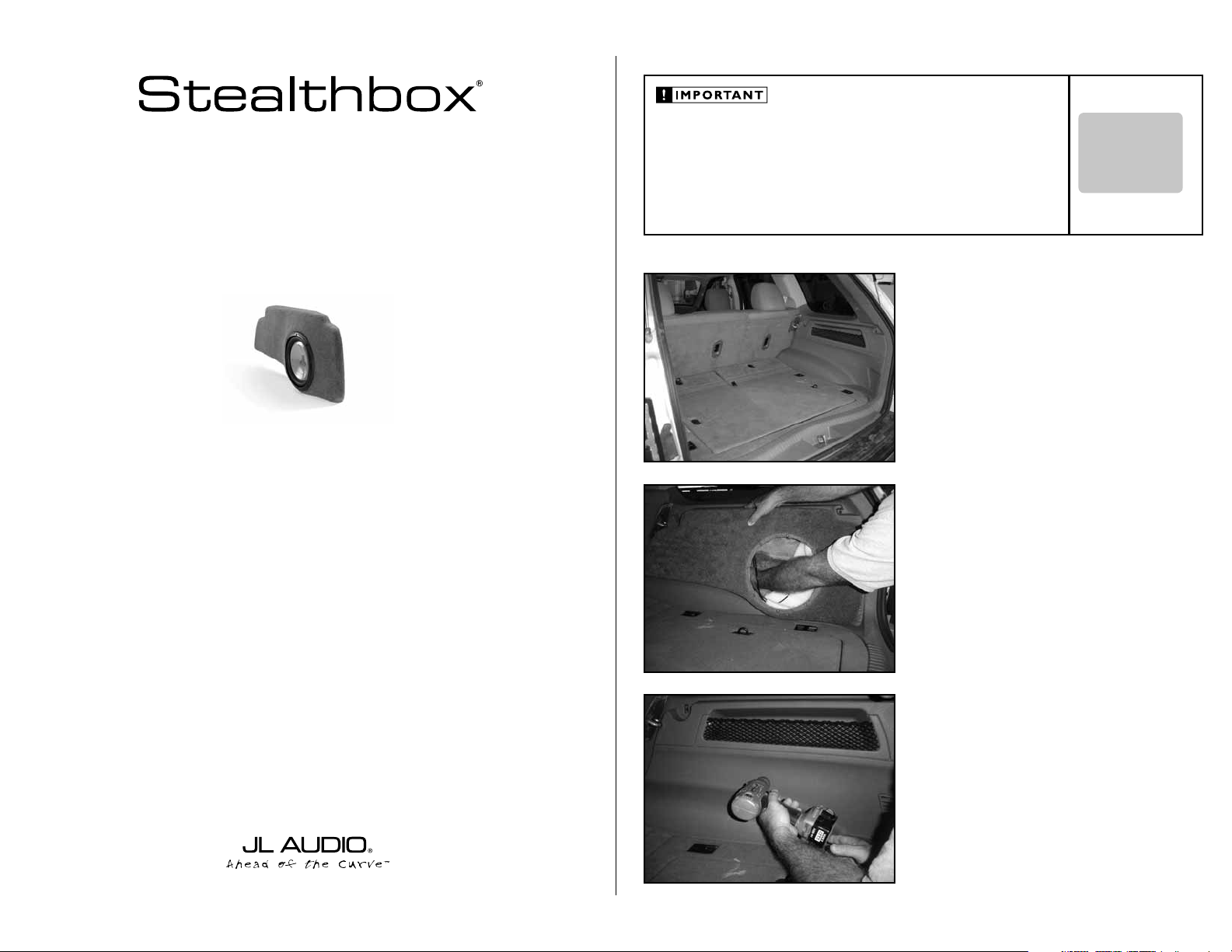
INSTALLATION GUIDE
for the
SB-J-GCHER3/10W1v2
2005 - Up Jeep Grand Cherokee
Thank you for choosing a JL Audio Stealthbox® for your automotive sound system. With proper
installation, your new vehicle-specific enclosed subwoofer system will deliver years of listening pleasure.
If you choose to perform the installation yourself, it is absolutely vital that
the Stealthbox
instructions. Failure to mount the enclosure properly presents two problems:
1) The sub-bass performance will suffer due to the movement of the enclosure
caused by the force exerted by the woofer(s).
2) A loose enclosure presents a serious safety hazard in the event of a collision
or sudden deceleration.
®
be properly mounted to the vehicle according to these
STEP 1
Remove any contents from the cargo area.
STEP 2
With a Phillips screw driver, remove the woofer from the
Stealthbox®.
INSTALLATION
DIFFICULTY:
OUT
OF
5
ESTIMATED TIME:
12 HOURS
We strongly recommend that you have your new Stealthbox® installed by your authorized JL Audio
dealer. The installation professionals employed by your dealer have the necessary tools and experience
to disassemble and reassemble your vehicle properly. Also, keep in mind that your warranty coverage
extends to 2 years if your system is installed or approved by your authorized JL Audio dealer. If you
prefer to perform your own installation, please read this installation guide completely
before beginning the process.
Place the Stealthbox® onto the right side
wheel well/side panel (mounting location).
With a pencil or marker, mark the location of the mounting
hole onto the side panel from inside the Stealthbox®.
STEP 3
Remove the Stealthbox® from the vehicle.
With an 3/8” drill bit and drill, drill a hole through the side
plastic panel at the marked location from STEP 2.
There is a metal side panel that is located about 4” behind
this plastic side panel. The metal side panel also needs to be
drilled with the 3/8” drill bit. If the drill bit being used is more
then 4” long, then once you’re through the plastic panel you
can then mark or drill through the metal panel.
If your drill bit is not long enough. Mark onto the metal panel
with a pencil or marker, through the hole that was drilled
through the plastic panel.
Continued on Next Page
Page 2
SB-J-GCHER3/10W1v2_INSTR_SKU#011235
SB-J-GCHER3/10W1v2_INSTR_SKU#011235
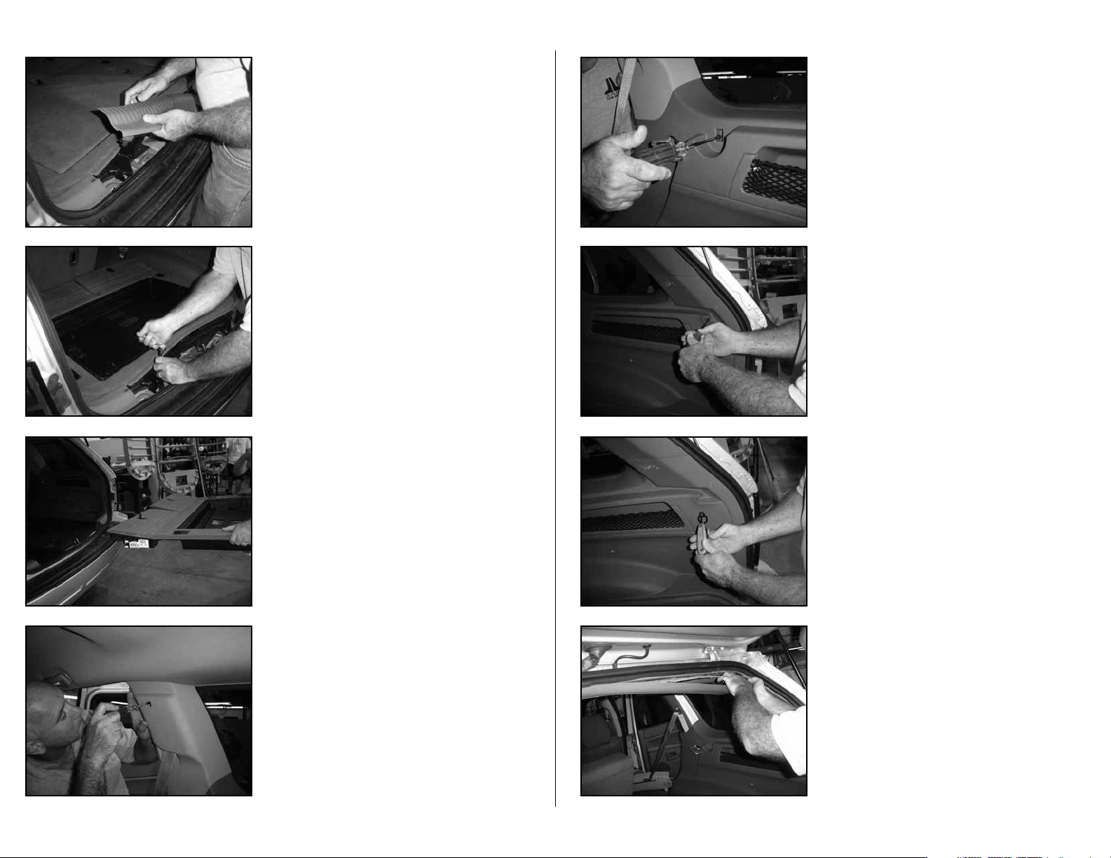
STEP 4
Remove the tailgate’s bottom sill plate.
STEP 5
Remove the false floor.
Remove the two mounting bolts that secure the flooring to
the vehicle.
STEP 6
Remove the flooring from the vehicle.
STEP 8
With a Phillips head screw driver, remove the screw from the
front section of the plastic side panel.
STEP 9
With a Phillips head screw driver, remove the screw from the
rear section of the plastic panel.
STEP 10
With an hex key, remove the screw and D-ring from the rear
section of the plastic panel.
Page 2 • JL Audio, Inc 2007
STEP 7
With a small flat head screw driver, pop off the small cover
that is located on the top half of the c-pillar.
With Phillips head screw driver, remove the screw that has
been exposed.
Remove this top half of the c-pillar.
STEP 11
Remove the tailgate’s upper sill plate.
Continued on Next Page
Page 3
SB-J-GCHER3/10W1v2_INSTR_SKU#011235
SB-J-GCHER3/10W1v2_INSTR_SKU#011235
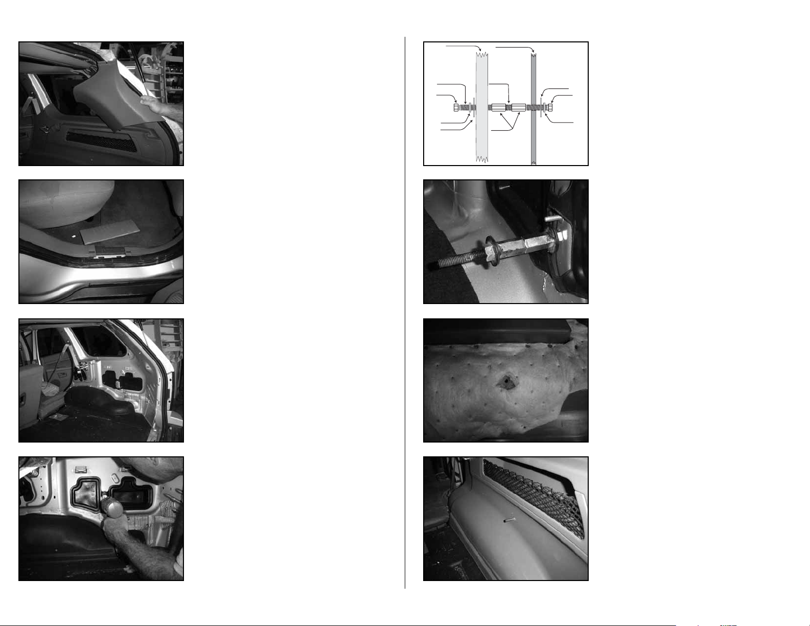
STEP 12
Remove the d-pillar plastic cover.
STEP 13
Remove the right rear door’s sill plate.
STEP 14
Remove the plastic panel from the vehicle.
STEALTHBOX WALL
SOCKET CUP SET SCREW
HEX NUT
LOCK WASHER
FLAT WASHER
VEHICLE SHEET METAL
SOCKET CUP SET SCREW
COUPLERS
FLAT WASHER
HEX BOLT
LOCK WASHER
STEP 16
The illust rati o n t o the left show s h o w all the supplie d
hardware makes up the mounting a ssemb ly.
Place a lo c k wash er and th en flat was h er onto t h e hex bol t.
Place bo th coupl er nut s o nto one so c k et cup set screw.
Make sure that there is enough room inside one of the
couplers to a l l o w the hex bo lt to be properly inser t e d, look
to STEP 17.
Fully threa d i n the seco n d s ocket cup set scr e w into the
other coupler.
STEP 17
Place the hex bolt assembly through the drilled hole, from
the back side of the metal panel.
Apply a wrench onto the coupler that is in front of the metal
side panel.
Apply a 9/16-inch open end wrench to the hex bolt that is
behind the metal panel.
Secure the mounti n g assembly to the met a l side panel.
STEP 18
From the back side of the plastic side panel, cut out and
remove the sound deadening that is around the drilled hole.
Page 3 • JL Audio, Inc 2007
STEP 15
If needed, with the 3/8” drill bit and drill. Drill the metal panel
were it was marked from STEP 3.
*WARNING*
The metal behind this side panel is the outer metal of the
vehicle.
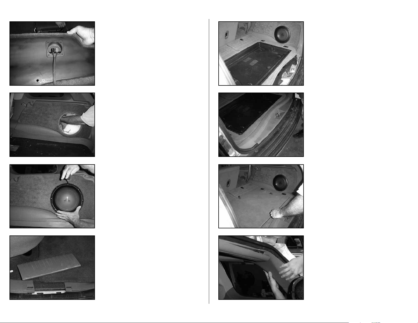
STEP 19
Place the plastic side panel back into place. Guide the socket
cup set screw through the drilled hole. Only the socket cup
set screw should protrude through the plastic panel.
Continued on Next Page
Page 4
SB-J-GCHER3/10W1v2_INSTR_SKU#011235
SB-J-GCHER3/10W1v2_INSTR_SKU#011235
STEP 20
Run speaker wire from the amplifier location to the
Stealthbox® location.
STEP 21
Place the Stealthbox® into the mounting area. Guide the
exposed socket cup set screw through the hole on the back
side of the Stealthbox®.
Place a supplied fender washer, flat washer, lock washer and
hex nut onto the socket cup set screw that is exposed inside
the Stealthbox®.
STEP 22
Wire and mount the woofer back into the Stealthbox®.
STEP 24
Place the flooring back into the vehicle from STEPS 5&6,
and secure.
STEP 25
Secure the tailgate’s bottom sill plate back into place, from
STEP 4.
STEP 26
Place the false floor back into the vehicle, from STEP 5.
Page 4 • JL Audio, Inc 2007
STEP 23
Place the right rear door’s sill plate back into place, from
STEP 13.
STEP 27
Secure the d-pillar cover back into place, from STEP 12.
Continued on Next Page
Page 5
SB-J-GCHER3/10W1v2_INSTR_SKU#011235
SB-J-GCHER3/10W1v2_INSTR_SKU#011235
JLA-SKU#011235 6-13-200
(1)
3/8-inch-16 x 1-inch Hex Tap Bolt
(1)
3/8-inch x 1-1/4-inch Fender Washer
(2)
Rod Coupling Nut (1) 3/8-inch-16 Hex Nut
(2)
3/8-inch Lock Washer (2) 3/8-inch-16 x 2-1/4-inch Socket Cup Set Screw
(2)
3/8-inch-16 x 2-1/4-inch Socket Cup Set Screw
Acoustic Suspension (sealed)
10W1v2
4 ohms mono
150 Watts
P O W E R R E C O M M E N D A T I O N
3.5-inch / Dash
TR350-CXi
6-inch x 9-inch / Front Doors
*TR690-TXi & *VR690-CXi
6.5-inch / Rear Door
TR650-CXi, VR650-CXi, *XR650-CXi & *C5-650x
*Spacers required for proper speaker installation.
STEP 28
With a Phillips head screw driver, secure the screw that was
remove in STEP 9.
The D-ring is not to be remounted.
STEP 29
Secure the c-pillar cover back into place.
With a Phillips head screw driver, secure the screw and the
little cover that was removed in STEP 7.
STEP 30
With a Phillips head screw driver, secure the screw that was
removed in STEP 9.
INCLUDED HARDWARE
(1)
3/8-inch-16 x 1-inch Hex Tap Bolt
(2)
Rod Coupling Nut (1) 3/8-inch-16 Hex Nut
(2)
3/8-inch Lock Washer (2) 3/8-inch-16 x 2-1/4-inch Socket Cup Set Screw
(2)
3/8-inch-16 x 2-1/4-inch Socket Cup Set Screw
(1)
3/8-inch x 1-1/4-inch Fender Washer
SPECIFICATIONS
Enclosure Type:
Driver Type:
Nominal Impedance:
Continuous Power Handling:
POWER RECOMMENDATION
Acoustic Suspension (sealed)
10W1v2
4 ohms mono
150 Wa t ts
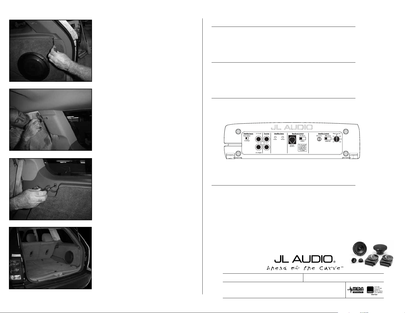
JL Audio recommends using a high quality amplifier such as the JL Audio A2150.
The diagram below shows the recommended crossover, infrasonic filter and equalizer settings for the A2150 when
being used to power your Stealthbox®.
The JL Audio A2150 is a very versatile audio component. Please consult the owner’s manual for even more
detailed information about installing and tuning this amplifier.
Page 5 • JL Audio, Inc 2007
CONGRATULATIONS
You have completed the installation for this model!
Please refer to the Power Recommendation section for an
amplifier recommendation and basic set-up help.
MID/HIGH FREQUENCY DRIVER FITMENT
A variety of JL Audio coaxial and component systems will fit in the factory speaker locations of you vehicle.
Front Speaker Size / Location:
Fits JL Audio Models:
Front Speaker Size / Location:
Fits JL Audio Models:
*TR690-TXi & *VR690-CXi
Rear Speaker Size / Location:
Fits JL Audio Models:
*Spacers required for proper speaker installation.
All specifications are subject to change without notice. “JL Audio®” and the JL Audio logo, “Stealthbox” and the Stealthbox logo are registered
trademarks of JL Audio, Inc. “Ahead of the Curve” and its respective logo is a trademark of JL Audio, Inc.
JLA-SKU#011235 6-13-20077 • Printed in USA • ©2007 JL Audio, Inc. • U.S. PATENTS: #5,734,734 #5,949,898 #6,118,884 #6,229,902 #6,243,479
#6,294,959 #6,501,844 #6,496,590 #6,441,685 #5,687,247 #6,219,431 #6,625,292 #D472,891 #D480,709 Other U.S. & Foreign patents pending.
For more detailed information please visit us online at www.jlaudio.com.
10369 NORTH COMMERCE PARKWAY • MIRAMAR, FLORIDA • 33025 • USA
TR650-CXi, VR650- CXi, *XR650-CXi & *C5-650x
3.5-inch / Dash
TR350-CXi
6-inch x 9-inch / Front Doors
6.5-inch / Rear Door
(954) 443-1100
www.jlaudio.com
 Loading...