

JL Audio SB-H-CRV-10W3v3-TN, SB-H-CRV-10W3V3, SB-H-CRV-10W3v3-DG, SB-H-CRV-10W3v3-GA, 94429 User Manual
Page 1
SB-H-CRV/10W3V3 INSTR_SKU#011281
I N S T A L L A T I O N G U I D E
for the
SB-H-CRV/10W3V3
SKU#94429
2007+
Thank you for choosing a JL Audio Stealthbox® for your automotive sound system. With proper
installation, your new vehicle-specific enclosed subwoofer system will deliver years of listening pleasure.
If you choose to perform the installation yourself, it is absolutely vital that
the Stealthbox
instructions. Failure to mount the enclosure properly presents two problems:
1) The sub-bass performance will suffer due to the movement of the enclosure
caused by the force exerted by the woofer(s).
2) A loose enclosure presents a serious safety hazard in the event of a collision
or sudden deceleration.
®
be properly mounted to the vehicle according to these
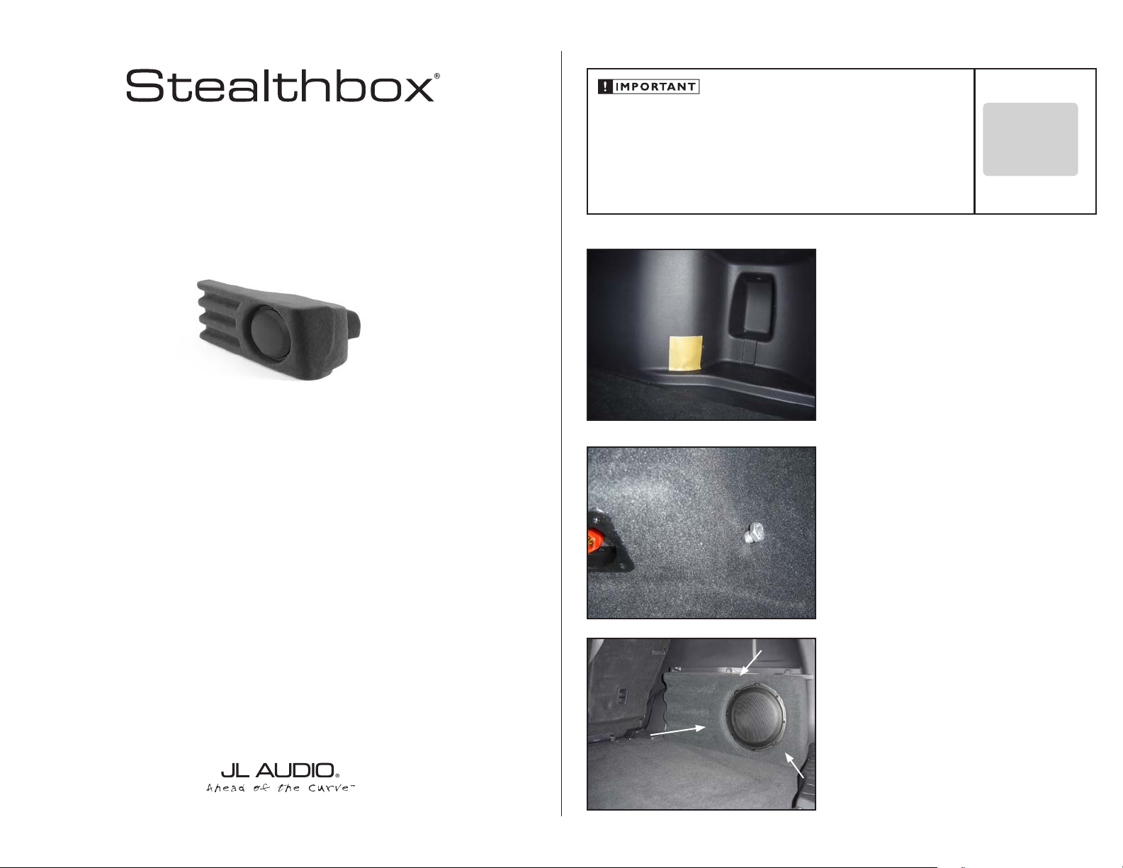
S T E P 1
Remove any contents in the trunk of the car so that you
will have a clean area to work in. Place the Wax Square as
shown
S T E P 2
Thread the included Hex Head Bolt into the enclosure so
that approximately 1/2” remains exposed (as shown).
INSTALLATION
D I F F I C UL T Y:
OU T
OF
35
ESTIMATED TIME:
23 HOURS
We strongly recommend that you have your new Stealthbox® installed by your authorized JL Audio
dealer. The installation professionals employed by your dealer have the necessary tools and experience
to disassemble and reassemble your vehicle properly. If you prefer to perform your own installation,
please read this installation guide completely
before beginning the process.
S T E P 3
Set the Stealthbox in place. Push in and, down as
indicated by the arrows to get the bolt to make an
impression in the wax square.
Continued on Next Page
Page 2
SB-H-CRV/10W3V3 INSTR_SKU# 011281
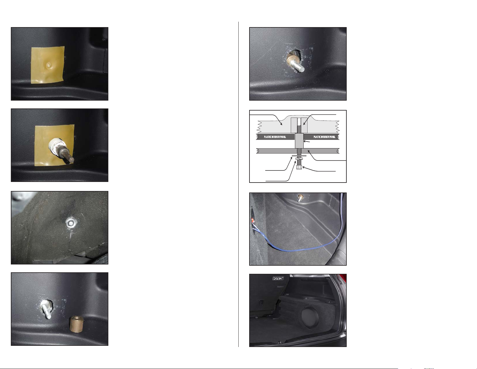
PLASTIC INTERIOR PANEL
STEALTHBOX WALL
THREADED INSERT
VEHICLE SHEET METAL
HEX HEAD BOLT
LOCK WASHER
FLAT WASHER
SPACER
PLASTIC INTERIOR PANEL
S T E P 4
Remove the enclosure, ensure that an adequate depression
has been made in the Wax Square to use it as a guide to
drill a hole. If the impression is not present, back the bolt
out of the enclosure and, repeat
STEP 3 untill there is a well
defined impression in the Wax Square.
S T E P 5
Using a 1 inch hole saw, drill and cut a hole through the
inner plastic panel. At the same time, drill the pilot hole only
through the metal inner fender panel.
*CAUTION*
Before drilling, always make sure that you are not
going to be drilling into any gas lines, brake lines,
transmission lines, electrical wiring, exhaust systems
or anything else that might cause a reduction in
your weekly pay. Always wear eye protection when
drilling.
S T E P 6
From inside the fender well, insert the Hex Head Bolt, Split
Lock Washer and Fender Washer through the hole drilled in
STEP 5
S T E P 8
Insert the Spacer over the Hex Head Bolt, through the 1” hole
in the interior plastic trim panel so that it will rest against the
metal interior fender panel.
S T E P 9
This illustration details how the hardware should be
arranged to mount the Stealthbox® securely.
S T E P 1 0
Hook up the wire from the amplifier to the Stealthbox®, and
test the Stealthbox® to ensure the correct operation. Have
a friend slide the Stealthbox®into postion while you turn the
Hex Head Bolt in order to get the threads started into the
Stealthbox®, tighten the fastners.
Page 2 • JL Audio, Inc 2008
S T E P 7
From inside the vehicle, the Hex Head Bolt should protrude
well past the interior plastic trim panel.
S T E P 1 1
C O N G R A T U L A T I O N S !
You have completed the installation for this model!
Enjoy your new Stealthbox®!
Please refer to the Power Recommendation section for an
amplifier recommendation and basic set-up help.
Continued on Next Page
Page 3

SB-H-CRV/10W3V3 INSTR_SKU# 011281
I N C L U D E D H A R D W A R E
1) 3/8” Split Lock Washer 1) 3/8” x 1 1/4” Fender Washer
1) 3/8-16 x 2 1/2” Hex Head Bolt 1) 3/8”(ID) x 1”Steel Spacer
S P E C I F I C A T I O N S
Enclosure Type: Acoustic Suspension (sealed)
Driver Type: 10W3v3-4
Nominal Impedance: 4 Ohms
Continuous Power Handling: 500 Watts
P O W E R R E C O M M E N D A T I O N
JL Audio recommends using a high quality amplifier such as the JL Audio 250/1v2.
The diagram below shows the recommended crossover, infrasonic filter and equalizer settings for the 250/1v2
when being used to power your Stealthbox
®
.
The JL Audio 250/1v2 is a very versatile audio component. Please consult the owner’s manual for even more
detailed information about installing and tuning this amplifier.
Page 5• JL Audio, Inc 2008
M I D / H I G H F R E Q U E N C Y D R I V E R F I T M E N T
A variety of JL Audio coaxial and component systems will fit in the factory speaker locations of you vehicle.
Front Speaker Size / Location: 6 1/2”- Front Doors
Fits JL Audio Models: TR650-CXi, TR650-CSi, VR650-CXi, VR650-CSi, C5-650, C5-650x & ZR650-CSi
Rear Speaker Size / Location: 6 1/2”- Rear Door
Fits JL Audio Models: TR650-CXi, TR650-CSi, VR650-CXi, VR650-CSi, C5-650, C5-650x & ZR650-CSi
(954) 443-1100
All specifications are subject to change without notice. “JL Audio®” and the JL Audio logo, “Stealthbox” and the Stealthbox logo are registered
trademarks of JL Audio, Inc. “Ahead of the Curve” and its respective logo is a trademark of JL Audio, Inc.
JLA-SKU# 011281 ©11-13-2008 • Printed in USA • ©2008 JL Audio, Inc. • U.S. PATENTS: #5,734,734 #5,949,898 #6,118,884 #6,229,902
#6,243,479 #6,294,959 #6,501,844 #6,496,590 #6,441,685 #5,687,247 #6,219,431 #6,625,292 #D472,891 #D480,709 Other U.S. & Foreign
patents pending. For more detailed information please visit us online at www.jlaudio.com.
1 0 3 6 9 N O R T H C O M M E R C E P A R K W A Y • M I R A M A R , F L O R I D A • 3 3 0 2 5 • U S A
w w w. j l a u d i o . c o m
 Loading...