

JL Audio SB-GM-TRLBLZR-10W3v3-TN, SB-GM-TRLBLZR-10W3v3-GA, SB-GM-TRLBLZR-10W3v3, SB-GM-TRLBLZR-10W3v3-DG, SB-GM-TRLBLZR-10W3v3-TP User Manual
Page 1

SB-GM-TRLBLZR /10W3v3_INSTR_SKU#011184
INSTALLATION GUIDE
for the
SB-GM-TRLBLZR/10W3v3
2002-Up Chevrolet Trailblazer
2002-Up GMC Envoy
2003-Up Buick Rainier
Thank you for choosing a JL Audio Stealthbox® for your automotive sound system. With proper
installation, your new vehicle-specific enclosed subwoofer system will deliver years of listening pleasure.
If you cho ose to perform t h e i nstal lation yo u rself, i t i s a b s olutel y vital that
the Stealthbox
instructi o n s. Failu r e t o m ount the enclosu r e p roperly p r esent s two probl ems:
1) The sub-bass per f o rmance will suf f er due to the movemen t o f the enclosure
caused by the force exerted by the woofe r(s).
2) A loo se enclosu r e p r esents a s e rious sa f ety hazard in t h e event of a coll i s i on
or sudden deceleration.
®
be prope rly moun t ed to the ve h i c l e a c cording to these
STEP 1
Remove all contents from the cargo area.
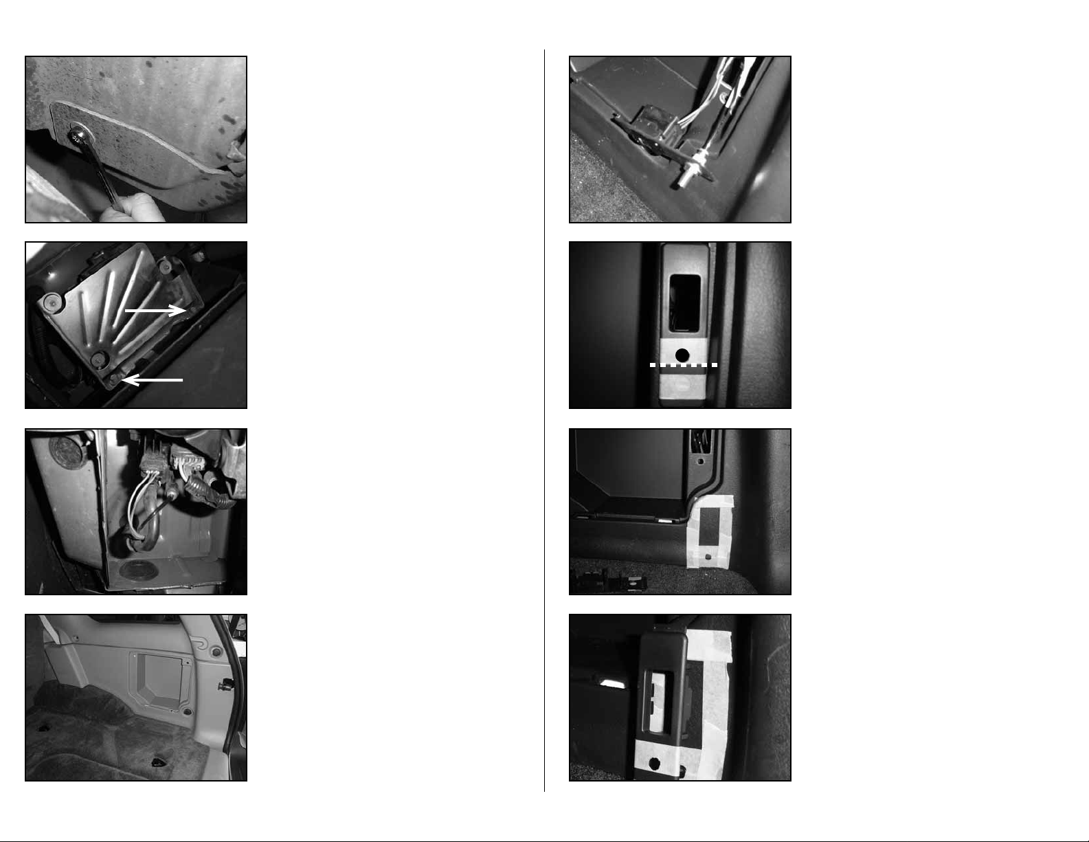
STEP 2
Wit h a 7mm s ocket, remo ve the two bolt s that are located
at the rear of the passenger's side rear wheel well.
INSTALLATION
DIFFICULTY:
OUT
OF
25
We strongly recommend that you have your new Stealthbox® installed by your authorized JL Audio
dealer. The installation professionals employed by your dealer have the necessary tools and experience
to disassemble and reassemble your vehicle properly. Also, keep in mind that your warranty coverage
extends to 2 years if your system is installed or approved by your authorized JL Audio dealer. If you
prefer to perform your own installation, please read this installation guide completely
before beginning the process.
STEP 3
Wit h a fla t b ald screw dri v er, remove the two pu sh/pull
tabs that are loca t ed behi nd the passenger's si de rear tire.
Continued on Next Page
Page 2
SB-GM-TRLBLZR /10W3v3_INSTR_SKU#011184
STEP 4
With a 10mm box/open end wrench, remove the bolt that
is located in front off the passen g er's side rear tire .
Wit h all the mounti n g h ardw are removed , remove the
plastic w h eel well l iner.
If your S UV does n ot have the fact o ry ai r compre ssor,
please go directly to STEP 7.
SUVs with the air compressor only.
STEP 5
Look up i nto the passe n g er's sid e rear w h eel well. You will
see th i s m etal p l ate as in the pictur e.
The ai r compressor in mounted onto t h i s plate . The pla t e i s
mounted to the chass is with two bolts .
Remove these two bolts.
SUVs with the air compressor only.
STEP 6
This co m press or is not to b e remove d out of th e wheel
well. Care f ully wed g e the comp resso r into the wheel w ell,
so it s tays. Some la rge zip t i es can be u s ed to tempora ry
mount the comp ressor out of t h e way.
SUVs with the air compressor only.
STEP 8
Pop out t he pane l that hol d the air co mpressor sw itch an d
hose nozzle.
Remove the hose nozzle from panel.
Pop the s witch o ut of the p anel, f rom the back sid e.
SUVs with the air compressor only.
STEP 9
Apply tape to the switch panel to mark your cut line and new
hose nozzle's mounting hole.
Drill a new mountin g hole for the hose nozzle as close to the
switch opening as possible.
Cut the bottom of the switch panel just below the new
mounting hole.
SUVs with the air compressor only.
STEP 10
The ai r compressor s witch p anel ne e ds to be mounted at
the lower rig h t corner, outsi d e the pock et onto t he side
panel.
Page 2 • J L A udio, Inc 2005
Make sure that you do no t kink a ny of the nylo n air hose.
STEP 7
Remove the st o rage d o or.
If your S UV does n ot have the fact o ry ai r compre ssor,
please go directly to STEP 14.
SUVs with the air compressor only.
STEP 11
The cut out of the side panel only needs to be as wide as the
switch hold clips that are on the bac k side of the switch panel.
The cut out of the side panel only needs to be as tall , as from
the bo ttom of the switch and to the top of the switch panel.
Do not cut the side pane l as tal l as the tongue that
is on th e top and the bac k side of the switch panel.
Mark the hose nozzle's mounting hole onto the side panel.
Continued on Next Page
Page 3

SB-GM-TRLBLZR /10W3v3_INSTR_SKU#011184
7-inches
STEP 12
Use a hand held rotary tool (Dremel®) wit h cutting bi t, to
cut out the si de panel f o r the comp ressor swi t c h panel .
Reme mber the hole fo r the hose n ozzle .
STEP 13
Place one of the supplie d wax sq uares, so th e s ide of the
wax s quare i s flu sh agai n st the p l astic side panel an d the
middle of the wax squ are measur es 7-inche s from the front
protrusion of the side plastic panel.
Not pictured. Place the seco nd suppl ied wa x square, so
the si d e o f the wa x square is f l ush aga inst t h e plastic side
panel and the m iddle of the wa x square measures 7-i nches
from the rear of the w h eel well t o the back o f the SUV.
STEP 14
Thr e ad the su p plied pa ir of socket cup se t s c rews in t o
the bottom of the Stealthbox®, leavi n g 1 /2-inch o f thread
exposed. Position the Stealthbox® in the mounting location
and press down on it firmly.
Remove the Stealthbox® carefully, le a ving the wax sq uares
in place. The socket cu p s et scre ws will leave imp ressi o ns in
the wax.
STEALTHBOX WALL
SILCONE SEALANT
FLAT WASHER
LOCK WASHER
HEX NUT
THREADED INSERT
VEHICLE SHEET METAL
FENDER WASHER
SOCKET CUP SET SCREW
STEP 16
Run sp eaker w i re fro m the amp lif i er loca tion to the
Stealthbox® loca t ion and check for p roper o peration of
the woofer.
STEP 17
Back o ut the so cket cup s et scre ws so 1 1/4-inch o f thre a d s
are exposed.
®
Place t h e S tealthbox
into position by guiding the socket
cup set screw s throu gh the ho l es drilled.
STEP 18
From under t he vehicle, place the supplied fender washers,
flat washers, lock washers and then hex nuts onto each
protrud ing socket cup set screw and secure. Adjust the
amount of exposed thread o n each cup set scr ew if
necessary keeping in mind that leaving too much exposed
tread will prevent the re-instal latio n of the air compressor
and or the plastic wheel well liner.
Note: For adde d pr ot e c ti on , i t i s rec om m en de d t h at
you appl y a be ad o f si li co ne b e t we e n t he ve hi c le a nd
the fen de r w a sh e r. Aft e r th e b ol t a ss e mb l y is t i gh t ly
secured, it is also recomme nded th at vehicle und ercoatin g m at e ri a l is a p pl ie d t o t he e x po se d a ss e mb l y.
Page 2 • J L A udio, Inc 2005
STEP 15
Note: Bef or e dr il li ng , m a ke su re t h at yo u are n o t goi n g
to be drilling into any gas lines, brake lines, transmission
lines, electrical wiring, transfer case (4x4 vehicles)
or anyt hi ng e l se t h a t mi gh t c au se a r ed uc t i on i n you r
weekly pay. Always wear eye protection when drilling!
Wit h a drill and a 1/2-inch drill bi t, dr i ll through th e
impressi o n m a de in the wax sq uare a nd into t h e v ehicle ’s
wheel well.
Remove the wax squa res.
If your S UV does n ot have the fact o ry ai r compre ssor,
please go directly to STEP 20.
SUVs with the air compressor only.
STEP 19
Mount the air compressor back into position.
Continued on Next Page
Page 4

SB-GM-TRLBLZR /10W3v3_INSTR_SKU#011184
STEP 20
Replace the pl asti c wheel w ell liner. Using a 10mm o pen/
closed combination w rench, re-install t h e bolt th at rem ov ed
in STEP 4.
STEP 21
Re-install th e p a ir of push/pull tabs removed in STEP 3.
STEP 22
With a 7mm socket and socket wrench, re-install the
pair of b o lts r emoved in STEP 2 .
INCLUDED HARDWARE
(2) 3/8-inch Split Lock Washer (2) 3 x 3-inch Wax Square
(2) 3/8-inch Flat Washer (2) 3/8-inch Hex Nut
(2) 3/8- in ch x 1 1/4-inch Fende r Washer
(2) 3/8-in c h 16 x 2 1/4-in c h Socket C up Set S c rews
SPECIFICATIONS
Enclo su re Type : Acous tic Suspension (sealed)
Driver Type: 10W 3v3-4
Nominal Impedance: 4 ohms mono
Contin uo u s Power H a nd li ng: 300 Watts
POWER RECOMMENDATION
JL Audio recomm ends using a high q uality amplif i er such as the JL Audio 250/1.
The di a gram below sh ows the r e commen ded crossover, infraso n ic fi lter an d equalizer settin gs for the 250/1
when being used to power your Stealthbox®.
+12VDC Ground Remote
JL AUDIO 250/1
monoblock subwoofer amplifier
Preamp Output Section
Output Mode
Full-Range/Low-Pass/High-Pass
Left Ch.
Right Ch.
Bass Control
Infrasonic Filter
Off/30Hz
+7
+3
+1
LF Boost (dB)
+10
+13
Amp LP Filter
Mode/Slope
Off/12dB/24dB
Filter Freq. (Hz)
Amplifier Input Section
Input Voltage
Low/High
Left Ch.
Input Sens.
Right Ch.
Signal Sensing
Off/On
The JL Audio 250/1 is a very ver satile audio component. Please consult the owner’s manual for even more
detailed information about installing and tuning this amplifier.
Page 3 • J L A udio, Inc 2005
CONGRATULATIONS
You have completed the installation for t his mode l!
Plea se refer t o the Power R e commen datio n s ecti on for an
amplifi er recommend ation a n d b asic set-up he l p.
MID/HIGH FREQUENCIES DRIVER FITMENT
A var iety of JL Audi o co axia l and component syst ems will fit i n the factory spe aker locatio n s o f yo u v ehicle.
Front Sp e a ke r Si ze / L oc a t io n: 6.5-inch / Front Do o rs
Fits JL Audio Models*: TR650-CSi, TR650-CXi, VR650-CSi, VR650-CXi, XR650-CSi, XR650-CXi,
C5 -650, C5 -650x & ZR650- CSi
Rear Sp e ake r S i ze / L oc a ti o n : 6.5-inch / Rear Doors
Fits JL Audio Models*: TR650-CSi, TR650-CXi, VR650-CSi, VR650-CXi, XR650-CSi, XR650-CXi,
C5 -650, C5 -650x & ZR650- CSi
* Will f it with minor modifica tions
(954) 443-1100
All specifications are subject to change without notice. “JL Audio®” and the JL Audio logo, “Stealthbox” and the Stealthbox logo are registered
trademarks of JL Audio, Inc. “Ahead of the Curve” and its respective logo is a trademark of JL Audio, Inc.
JLA-SKU#011184-04-25-2007 • Printed in USA • ©2005 JL Audio, Inc. • U.S. PATENTS: #5,734,734 #5,949,898 #6,118,884 #6,229,902
#6,243,479 #6,294,959 #6,501,844 #6,496,590 #6,441,685 #5,687,247 #6,219,431 #6,625,292 #D472,891 #D480,709 Other U.S. & Fo re ig n
patents pending. For more detailed information please visit us online at www.jlaudio.com.
10369 NORTH COMMERCE PARKWAY • MIRAMAR, FLORIDA • 33025 • USA
www.jlaudio.com
 Loading...