

SB-GM-TAHOCNSL/10W1v2
2007 - Up
Chevrolet / GMC Full-Size SUV’s & Truck
Avalanche, Suburban, Tahoe, Yukon & Yukon XL
with bucket seats and
factory console
SB-GM-TAHOSCNSL/10W3v2_INSTR_SKU#011220
SB-GM-TAHOSCNSL/10W3v2_INSTR_SKU#011220
3
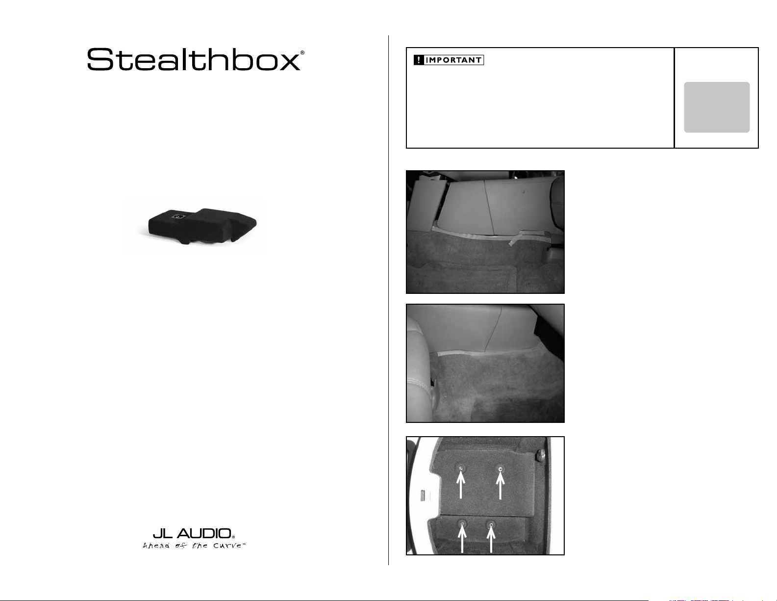
INSTALLATION GUIDE
for the
SB-GM-TAHOCNSL/10W1v2
2007 - Up
Avalanche, Suburban, Tahoe, Yukon & Yukon XL
Thank you for choosing a JL Audio Stealthbox® for your automotive sound system. With proper
installation, your new vehicle-specific enclosed subwoofer system will deliver years of listening pleasure.
We strongly recommend that you have your new Stealthbox® installed by your authorized JL Audio
dealer. The installation professionals employed by your dealer have the necessary tools and experience
to disassemble and reassemble your vehicle properly. Also, keep in mind that your warranty coverage
extends to 1 year if your system is installed or approved by your authorized JL Audio dealer. If you
prefer to perform your own installation, please read this installation guide completely
Chevrolet / GMC Full-Size SUV’s & Truck
with bucket seats and
before beginning the process.
factory console
If you choose to perform the installation yourself, it is absolutely vital that
the Stealthbox
instructions. Failure to mount the enclosure properly presents two problems:
1) The sub-bass performance will suffer due to the movement of the enclosure
caused by the force exerted by the woofer(s).
2) A loose enclosure presents a serious safety hazard in the event of a collision
or sudden deceleration.
®
be properly mounted to the vehicle according to these
STEP 1
Using masking tape or similar, mark where the bottom
edge of the front center console meets the carpet on the
driver’s side.
STEP 2
Using masking tape or similar, mark where the bottom
edge of the front center console meets the carpet on the
passenger’s side.
STEP 3
Open the storage lid of the center console. Remove the four
exposed screws.
INSTALLATION
DIFFICULTY:
OUT
OF
5
Continued on Next Page
SB-GM-TAHOSCNSL/10W3v2_INSTR_SKU#011220
SB-GM-TAHOSCNSL/10W3v2_INSTR_SKU#011220
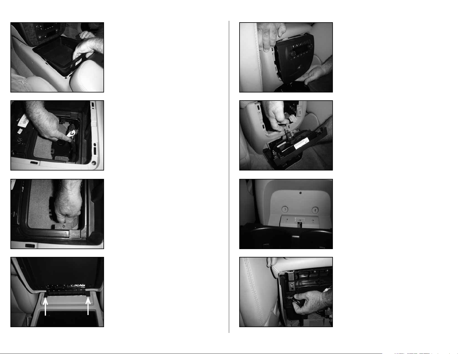
STEP 4
Remove the cup ho lders from center co n s ole by pull ing
upwards.
STEP 5
With the cup holders removed, look through the
opening and disconnect the exposed wiring harness plug.
STEP 6
Pull the wiring harness off the tab.
STEP 8
Pr y the rear face to t h e rear of the vehicle.
STEP 9
Remove all plugs from the rear face pl ate.
STEP 10
From the back side of the center console, fold down the
cup holder s.
Remove two screws be hind th e c up holders a s w ell as t h e
three scre w s securing th e cup holder to the ce nter console.
Page 2 • JL Audio, Inc 2006
STEP 7
*Read S te p 7 & S te p 8 b e fo re a t t e mp t in g t he r em ov al o f
the rea r f ac e pl at e .*
Car e fully p ry up a nd back on the two black t abs on either
side of the console’s door hinge.
Extra care should be used in a effort to prevent
break i ng t h es e t a bs .
Remove the back panel from the center console.
STEP 11
Remov e the wiring harne ss that is secured to t h e driv er’s
side of the center console.
Continued on Next Page

SB-GM-TAHOSCNSL/10W3v2_INSTR_SKU#011220
SB-GM-TAHOSCNSL/10W3v2_INSTR_SKU#011220
STEP 12
Remove the wiring harne ss that i s s ecure d to the passen g er
side of the center console.
STEP 13
Remove the pair of screws that are found on each side of the
center console.
If the seat(s) are powered, bring the seat(s) to their highest
height and all the back to access the front screws. Bring the
seats all the way forward to access the rear screws.
If the seat(s) are manual, bring the seat(s) all the way back
and access the screws from under the seats, as in the picture.
STEP 14
Remove the center console from the vehicle.
4-inches
7 1/4-inches
7 1/4-inches
1 1/2-inches
STEP 15B
The op ening w ith th e tabs cut off.
STEP 16
Cut out a pair of 2- inch x 2-in c h squares, o ut of the c arpet.
Driver side:
4-inches from the driver’s side tape line to the right.
7 1/4-inch e s from t h e rear of the hum p ( that r uns the w idth
of the transmission hum p ) forward .
Passenger side:
1 1/2-inches from the p asse n g er’s tape lin e t o the left.
7 1/4-inch e s from t h e rear of the hum p ( that r uns the w idth
of the transmission hum p ) forward .
STEP 17
Place the supp l ied pair o f wax sq uares onto th e areas that
were cut out in STEP 16.
Page 3 • JL Audio, Inc 2006
STEP 15A
With the center console out of the vehicle, cut off the tabs
that protrude down from the cup holder area.
STEP 18
Thread the supplied pair of socket cup set screws into the
bottom of the Stealthbox®, leaving 3/4-inches exposed.
Continued on Next Page

SB-GM-TAHOSCNSL/10W3v2_INSTR_SKU#011220
SB-GM-TAHOSCNSL/10W3v2_INSTR_SKU#011220
STEP 19
Posi tion the St ealthbo x® in the mounting location.
STEP 20
The front of the Stealthbox® fits against the black plastic
panel located on the passenger side.
STEP 21A
The rear of the Stealthbox® is to be fitted between a pair of
tabs that are protruding up from the flooring.
This is the driver’s side tab.
STEP 22
Once the Stealthbox
®
is in the mounting location, press
down on it firmly.
®
Remove the Stealthbox
carefull y, lea ving th e wax sq uares
in place. The s o c k et cup se t s c rews w i l l leave impres s ions in
the wax.
STEP 23
Note: Bef or e dr il li n g, m a ke su re t h at yo u ar e no t go in g
to be drilling into any gas lines, brake lines, transmission
lines, electrical wiring, transfer case (4x4 vehicles)
or anyt hi ng e l se t h at m ig h t c au se a re d uc t i on i n you r
weekly pay. Always wear eye protection when drilling!
Wit h a drill and a 1/2- i nch dr i l l bit, dril l throu gh the
impressi on made i n the wax squa re and i nto the vehicle ’s
transmission tunne l .
Remove the wax squa res and the ta pe.
STEP 24
Run sp eaker w i re fro m the am p l ifi er’s locatio n t o the
Stealthbox® loca t ion and check for p roper operatio n o f
the woofer.
Back o ut the socket cu p s et screws instal l ed in Step 18, to
expose 1 1/4-inch.
Page 4 • JL Audio, Inc 2006
STEP 21B
This is the passenger’s side tab.
STEP 25
Place t h e S tealthbox
®
into position by guiding the socket
cup set screw s throu gh the ho les dr i lled in Step 23.
Continued on Next Page

SB-GM-TAHOSCNSL/10W3v2_INSTR_SKU#011220
SB-GM-TAHOSCNSL/10W3v2_INSTR_SKU#011220
JLA-SKU#011220-24-200
((2)2) 3-inch x 3-inch Wax Square
(2)
3/8-16 x 2-1/4-inch Socket Cup Set Screw
(2)
3/8-inch x 3/4-inch USS Flat Washer
(2)
3/8-inch-16 Hex Nut
(2)
3/8-inch x 2-inch Fender Washer
(2)
3/8-inch Split Lock Washer
Acoustic Suspension (sealed)
10W1v2-4
4 ohms mono
150 Watts
6.5-inch / Front Doors
TR650-CXi, VR650-CSi, VR650-CXi, XR650-CSi, XR650-CXi & ZR650-CSi
6.5-inch / Rear Doors
TR525-CXi, VR525-CXi & XR525-CXi
STEALTHBOX WALL
SILCONE SEALANT
FLAT WASHER
LOCK WASHER
HEX NUT
THREADED INSERT
VEHICLE SHEET METAL
FENDER WASHER
SOCKET CUP SET SCREW
STEP 26
Place t he wire harness to the left side of the Stealthbox®.
STEP 27
From under the vehicle, place the s upplied fend er washers,
flat washers, lock washers and then hex nuts onto each
protruding socket cup set screw and secure. Adjust the
amount of exposed thread on each cu p set screw if
necessary.
Note: For adde d p rot e c t io n, i t i s re co mm e nd ed t h at
you appl y a be ad o f si li co ne b e t we e n t he ve hi c le a nd
the fen de r w a sh e r. Aft e r th e b ol t a ss e mb l y is t i gh t ly
secured, it is also recomme nded th at vehicle und ercoatin g m at e ri a l is a p pl ie d t o t he e x po se d a ss e mb l y.
STEP 28
Attach the speaker wire to the terminal.
In reverse order from Step 14 to Step 1, replace the factory
components back together.
INCLUDED HARDWARE
3-inch x 3-inch Wax Square
(2)
3/8-inch x 3/4-inch USS Flat Washer
(2)
3/8-inch x 2-inch Fender Washer
(2)
3/8-inch Split Lock Washer
(2)
3/8-16 x 2-1/4-inch Socket Cup Set Screw
(2)
3/8-inch-16 Hex Nut
SPECIFICATIONS
Enclosure Type:
Driver Type:
Nominal Impedance:
Continuous Power Handling:
Acoustic Suspension (sealed)
10W1v2 -4
4 ohms mono
150 Wa t ts
POWER RECOMMENDATION
JL Audio recommends using a high quality amplifier such as the JL Audio A2150.
The diagram below shows the recommended crossover, infrasonic filter and equalizer settings for the A2150 when
being used to power your Stealthbox®.
The JL Audio A2150 is a very versatile audio component. Please consult the owner’s manual for even more
detailed information about installing and tuning this amplifier.
MID/HIGH FREQUENCY DRIVER FITMENT
Page 5 • JL Audio, Inc 2006
CONGRATULATIONS
You have completed the installation for this model!
Please refer to the Power Recommendation section for an
amplifier recommendation and basic set-up help.
A variety of JL Audio coaxial and component systems will fit in the factory speaker locations of you vehicle.
Front Speaker Size / Location:
Fits JL Audio Models:
Rear Speaker Size / Location:
Fits JL Audio Models:
All specifications are subject to change without notice. “JL Audio®” and the JL Audio logo, “Stealthbox” and the Stealthbox logo are registered
trademarks of JL Audio, Inc. “Ahead of the Curve” and its respective logo is a trademark of JL Audio, Inc.
JLA-SKU#011220-24-20066 • Printed in USA • ©2005 JL Audio, Inc. • U.S. PATENTS: #5,734,734 #5,949,898 #6,118,884 #6,229,902 #6,243,479
#6,294,959 #6,501,844 #6,496,590 #6,441,685 #5,687,247 #6,219,431 #6,625,292 #D472,891 #D480,709 Other U.S. & Foreign patents pending.
For more detailed information please visit us online at www.jlaudio.com.
10369 NORTH COMMERCE PARKWAY • MIRAMAR, FLORIDA • 33025 • USA
6.5-inch / Front Doors
TR650-CXi, VR650-CSi, VR650- CXi, XR650-CSi, XR650 -CXi & ZR650-CSi
6.5-inch / Rear Doors
TR525-CXi, VR525-CXi & XR525-CXi
(954) 443-1100
www.jlaudio.com
 Loading...