

Page 1
➔
➔
➔
➔
➔
Stealthbox
®
INSTALLATION GUIDE
for the
SB-F-TRKCTR3/10W3
(Fits 2001-Up Standard Cab, Super-Cab
and Super-Crew trucks
lso fits, 2001 Harley Davidson and King
Ranck trucks)
This Stealthbox is a product
which requires professional
installation skills and tools.
Please read this installation guide
thoroughly before beginning the
project. It will guide you step by
step through the installation.Several
of the steps in this process may
require two people to accomplish.
It is absolutely vital that the
enclosure be properly mounted to
the vehicle according to these
instructions. Failure to mount the
enclosure properly presents two
problems: 1) The sub-bass
performance will suffer due to the
movement of the enclosure caused
by the force exerted by the
woofer(s) and 2) A loose enclosure
presents a serious safety hazard in
the event of a collision or sudden
deceleration.
Please enjoy your JL Audio
Stealthbox responsibly.
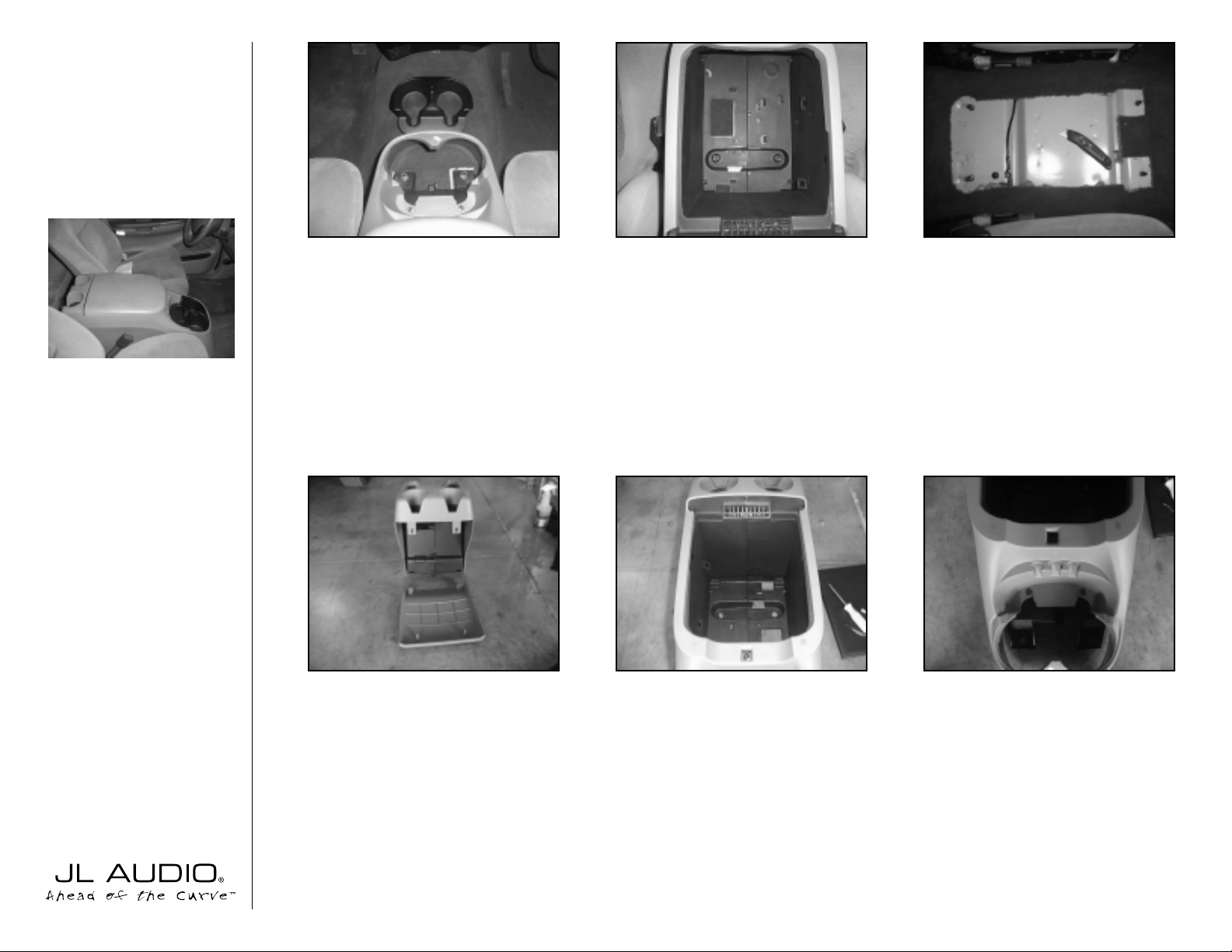
STEP 1:
Remove the front cup holder to
reveal two 18mm bolts. Remove these bolts.
STEP 2:
Remove tray and liner to reveal two
18mm bolts. Remove these bolts. Remove
console from truck.
STEP 3:
Cut and remove the carpet under
the console as shown in the picture.
**WARNING**
Seat Belt sensor wire runs underneath this
carpet. DONO TCUTTHIS WIRE!
STEP 4:
Remove (unsnap) the rear panel of
the console.
STEP 5:
Remove the armrest lid of the
console by removing four Phillips head screws.
STEP 6:
Remove the 7mm bolt that is
exposed when console top is removed.
STEP 7:
Remove three 7mm bolts denoted
by the arrows in the picture.
START
HERE
Continued on Page 2 ➔
➔
➔
➔
➔
➔
➔
➔
Page 2
➔➔
➔➔➔
➔
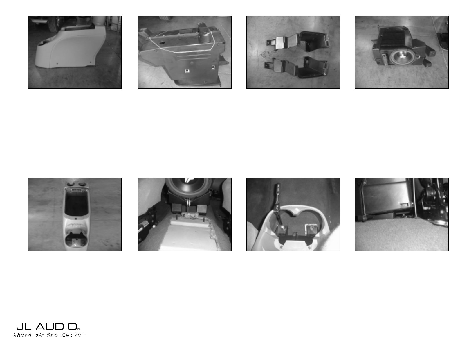
STEP 8:
Remove the four screws (two per
side) from the sides of the console.
STEP 13:
Reinstall the outside console over
the inner console and the Stealthbox with
eight 7mm bolts which were removed in
steps 6,7 and 8. Place the conlose/Stealthbox
back into the truck.
Cont.
From
age 1
Continued on Page 3 ➔
➔
STEP 9:
A large section of the bottom of the
console must be removed. The cut travels
from side to side 3/4”in front of the bolt at
the rear the bottom of the console (point
#1). This cut then angles down to meet the
edge of the bottom rib on the side of the
enclosure (point #2). The cut tr avels to the
other end of the rib(point #3) and then
angles up the side and across the bottom so
as to meet a point 1/2”inside the bolt at the
front of the bottom of the console (point
#4). The same path is taken on the other side
of the console.
STEP 14:
Run speaker wire so that it is
accessible at the front of the enclosure,
connect it to the enclosure and test for
proper operation.
➔
STEP 15:
Using an an 18mm socket wrench,
secure the front of the console to the vehicle
with the 18mm bolts removed in Step 1.
STEP 16:
Using an an 18mm open end
wrench, secure the rear of the console to
the vehicle with the 18mm bolts removed in
Step 4.
STEP 17:
Snap rear panel (removed in step
4) back unto rear of console.
STEP 18:
Reinstall cup holders (removed in
Step1).
STEP 10:
Remove the nine remaining 7mm
bolts to separate the inner console.
STEP 11:
Sandwich the Stealthbox between
the two halves of the inner console and
secure using the nine 7mm bolts removed in
step 10.
STEP 12:
Glue the two supplied 8”x8”pieces
of carpet to the sides of the inner console
(one per side).
➔
➔
➔
➔
➔
➔
➔
4
3
2
1
Bottom Rib
Page 3

Specifications:
Enclosure T ype: Acoustic Suspension (Sealed)
Driver T ype: One JL AUDIO 10W3-D6 Subwoofer
Nominal Impedance: 3Ω
Cont. Power Handling: 250 Watts
JLAudio recommends using a high quality amplifier such as the JLAudio 250/1. The diagram below shows the recommended
crossover, infrasonic filter and equalizer settings for the 250/1 when being used to power the the F-150 Stealthbox®.
Included Hardware:
(1) Replacement Tray
(2) 8”x8” Carpet Pieces
10369 N. Commerce Pkwy, Miramar, Florida 33025-392 Phone: 954.443.1100 Fax: 954.443.1111
+12VDC Remote Preamp Output SectionGround
JL AUDIO 250/1
monoblock subwoofer amplifier
Left Ch. Right Ch. Left Ch. Right Ch.
Full-Range/Low-Pass/High-Pass
Output Mode
Amp LP Filter
40
45
556585
120
200
Filter Freq. (Hz)
Mode/Slope
Off/12dB/24dB
Bass Control
0
+1
+3+7+10
+13
+15
LF Boost (dB)
Infrasonic Filter
Off/30Hz
Amplifier Input Section
Input Voltage Input Sens.
Low/High
Signal Sensing
Off/On
Subwoofer Output
MONO OUTPUT ONLY
The JLAudio 250/1 is a very versatile audio component. Please consult the owner’s manual for detailed information
about installing and tuning this amplifier.
➔
STEP 19:
Reinstall console top (removed in
Step 5) and place supplied tray into console.
Cont.
From
Page 2
➔
Mid/High Frequency Driver Information:
CONGRATULATIONS!
INSTALL COMPLETE.
XR570-CSi
XR570-CXi
Front Location Driver Size:
5"x7” (1271mm x 177.8mm)
Applicable JL Audio Products:
TR570-CXi, XR570-CXi or CSi
Rear Location Driver Size:
5"x7” (1271mm x 177.8mm)
Applicable JL Audio Products:
TR570-CXi, XR570-CXi or CSi
Estimated Installation Duration:
 Loading...