

JL Audio SB-F-SUPRCNSL/10W3v2 Installation Manual
➔
➔
➔
➔
Stealthbox
®
INSTALLATION GUIDE
SB-F-SUPRCNSL/10W3V2, JL AUDIO, Inc 2005
Sheet SKU#011149 Revision 8/4/2005 Page 1
for the
SB-F-SUPRCNSL/10W3v2
(‘98-Up Ford SuperDuty
250,350,450,550 & 650
‘00-Up Excursion)
This Stealthbox is a product which
requires professional installation skills and
tools.
Please read this installation guide thoroughly before beginning the project. It
will guide you step by step through the
installation.Several of the steps in this
process may require two people to
accomplish.
It is absolutely vital that the enclosure
be properly mounted to the vehicle
according to these instructions. Failure
to mount the enclosure properly presents two problems: 1) The sub-bass
performance will suffer due to the
movement of the enclosure caused by
the force exerted by the woofer(s) and
2) A loose enclosure presents a serious
safety hazard in the event of a collision
or sudden deceleration.
Please enjoy your JL Audio Stealthbox
responsibly.
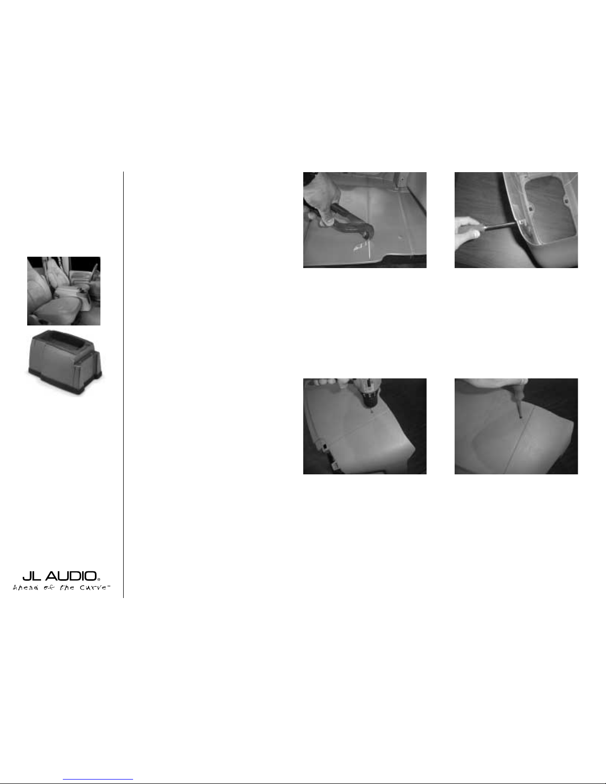
STEP 1:
From inside the factory console ,
using a 9/16”socket, remove the four bolts
that secure the console to the vehicle. ( Two
of these bolts will be used later to secure
the Stealthbox).
STEP 2:
Remove the console from the vehicle.
STEP 3:
Remove the inside section of the
console. (This will not be reinstalled).
-Two screws are located under the front tray.
-Three screws attach the hinge.
-Three screws are located on each side of the
consoles shell (six total)
After this section is removed,the console shell
will be in two parts.
STEP 4:
Using a pair of pliers, from the inside
of the console shell.Remove the ridges located toward the front of the console.
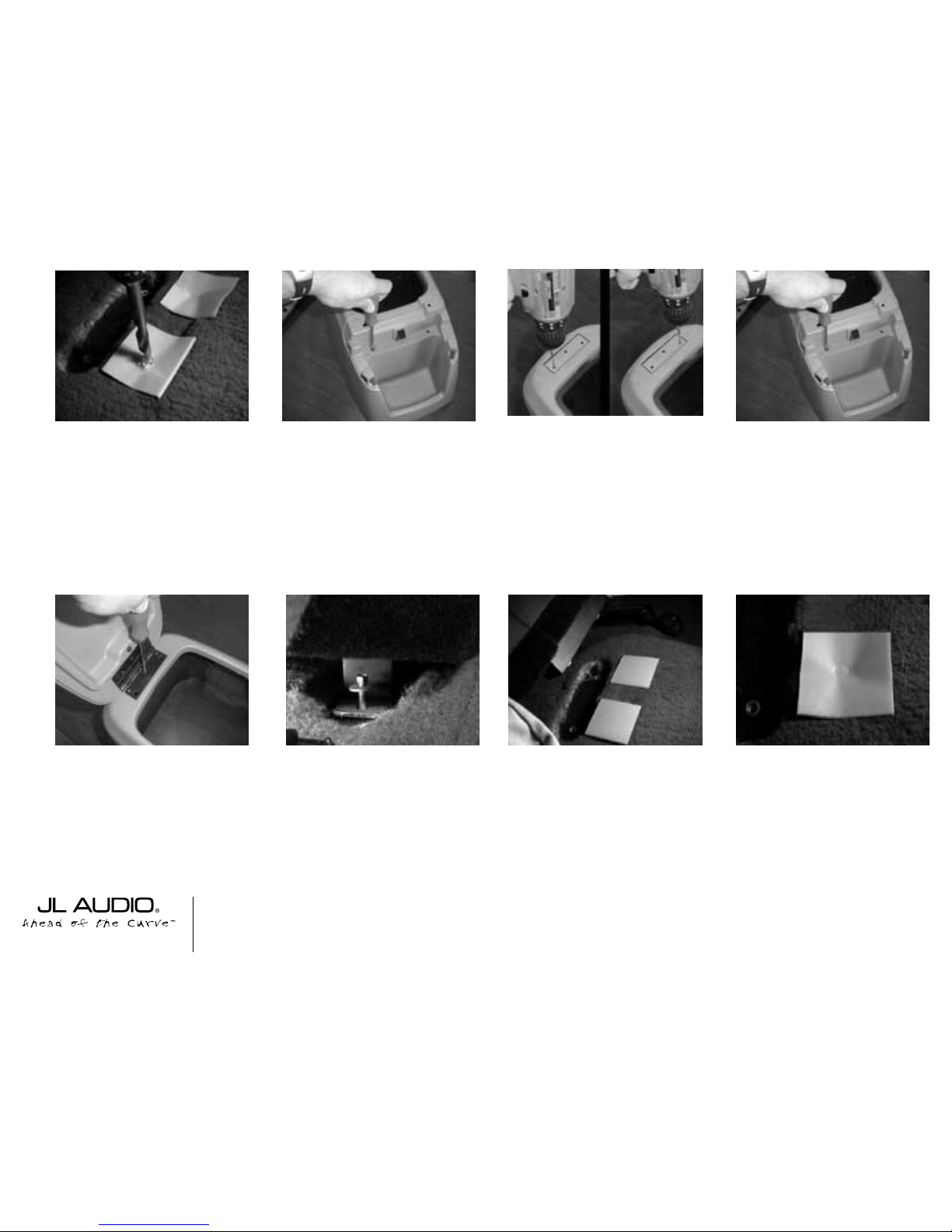
STEP 5:
Reassemble the front and rear parts
of the console shell using the supplied hardware (4 #8 x 1/2”long screws, 4 washer and
4 nuts) as shown in the picture.
STEP 6:
Turn the console shell upside down.
Position the Stealthbox inside the shell,
START
HERE
Continued on Next Page ➔
www.jlaudio.com
➔
➔
STEP 7: Use the remaining mounting holes as a
drill guide.
Using a 1/8” drill bit and drill, drill a hole through
each of these guide holes, into the Stealthbox.
STEP 8: Install #8x 1/2” black pan-head screws
into the drilled holes.
➔➔
➔➔➔
STEP 10: Install #8 x 1/2” black pan-head screws
into the drilled holes.
Cont..
From
Previous
Page
Continued on Next Page ➔
➔
STEP 11: Using a 1/8” drill bit and drill. Dr ill two
holes at the hinge area using the outside holes only.
The center hole does not need to be drilled.
➔
STEP 12: Remove the screws installed in STEP 8
and STEP 10. Separate the console shell from the
Stealthbox.
STEP 13: Attach the OEM’s console lid to the
shell. Use one of the OEM’s screws and supplied
speed-clip to the center hole of the hinge.
STEP 9: Turn the console right-side-up with the
Stealthbox attached.
Using the holes on the top of the console shell as
guides, use a 1/8” dr ill bit and dr ill to dr ill holes
through each of these guide holes and into the
Stealthbox.
SB-F-SUPRCNSL/10W3V2, JL AUDIO, Inc 2005
Sheet SKU#011149 Revision 8/4/2005 Pag e 2
www.jlaudio.com
STEP 14: Place the Stealthbox in the vehicle. Using
a pair of OEM bolts, from STEP 1.Loosely secure
the rear foot bracket to the floor,do not tighten.
STEP 15: Remove the paper backing on the supplied sheet wax squares.
With the Stealthbox in place, lift the front of the
Stealthbox and position both supplied sheet wax
squares onto the carpet and lined up with the front
foot bracket of the Stealthbox, lower the console
down.
STEP 16: Using one of the supplied 3/8”x1-1/2”
bolts, place the bolt through each hole of the front
foot bracket (one at a time). Press down on the bolt,
too leave impressions on the sheet wax squares.
STEP 17: Remove the two OEM bolts from STEP
14. Remove the Stealthbox from the vehicle.
 Loading...