

Page 1
INSTALLATION GUIDE
for the
SB-F-EXPL3/10W3v3
SKU# 94520
2011
Thank you for choosing a JL Audio Stealthbox® for your automotive sound system. With proper installation, your new
vehicle-specific enclosed subwoofer system will deliver years of listening pleasure.
We strongly recommend that you have your new Stealthbox® installed by your authorized JL Audio dealer. The
installation professionals employed by your dealer have the necessary tools and experience to disassemble and
reassemble your vehicle properly. Also, keep in mind that your warranty coverage extends to 2 years if your system is
installed or approved by your authorized JL Audio dealer. If you prefer to perform your own installation, please read
this installation guide completely
before beginning the process.
If you choose to per form the installation yoursel f, it is abso lutely vital that
the Stealthbox
®
be properly mounted to the vehicle accord ing to these
instructions . Failure to mo unt the enclosure properly present s two problems:
1) The sub-bass per formance will suffer due to the movem ent of the enclosure
caused by the force exe rted by the woofer(s).
2) A loose enclosure pres ents a serious safety haza rd in the event of a collision
or sudden deceleration.
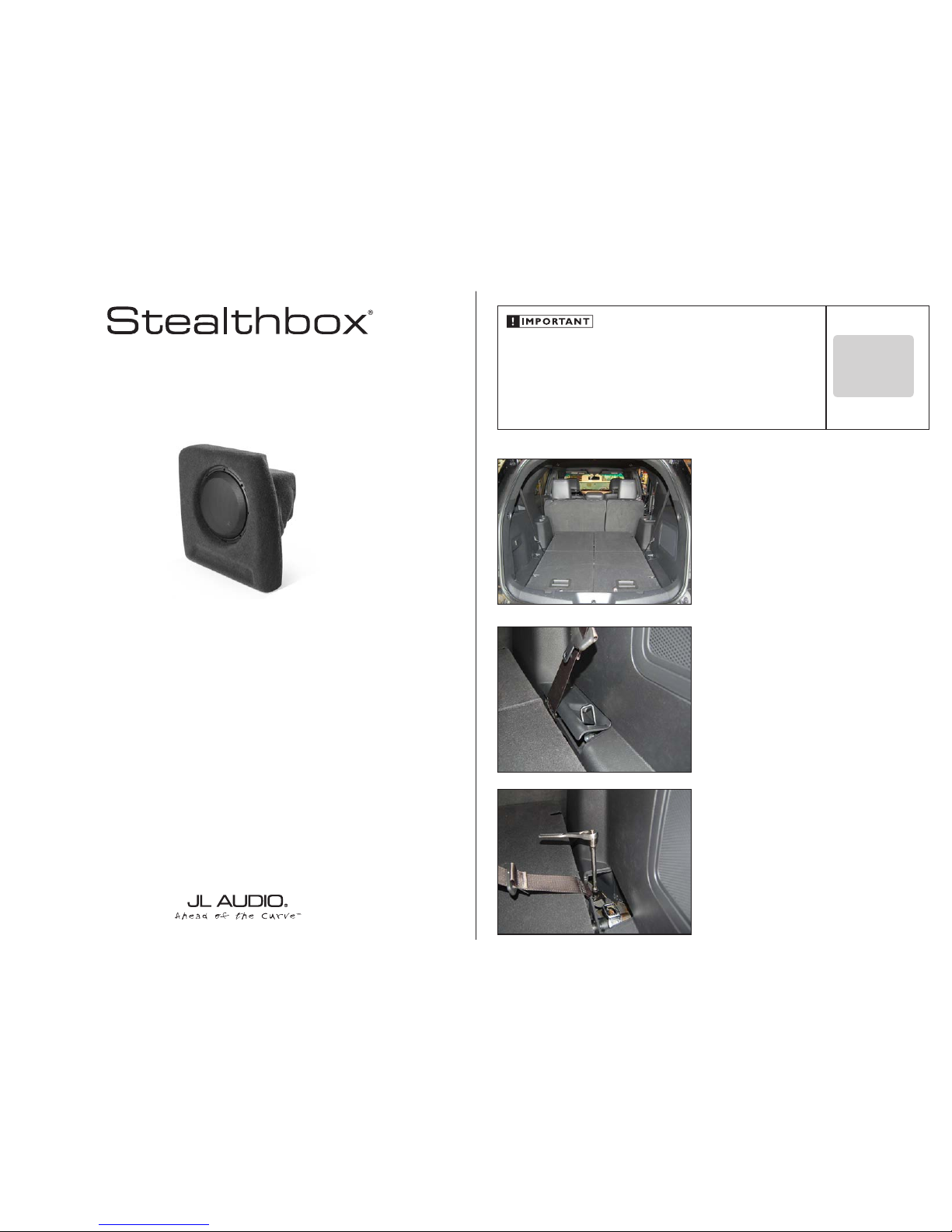
STEP 1
Empty out the cargo area so that you have a clean area to
work in.
Continued on Next Page
STEP 2
With the third row seats folded down, unclip the small trim
panel near the seat belt.
STEP 3
Remove the bolt holding the seat belt in place.
SB-F-EXPL3/10W3v3 INSTR_SKU# 011325
IN STALL ATIO N
DIFFICULTY:
35
OUT
OF
ESTIMATED TIME:
2 HOUR
Page 2
Continued on Next Page
SB-F-EXPL3/10W3v3 INSTR_SKU# 011325
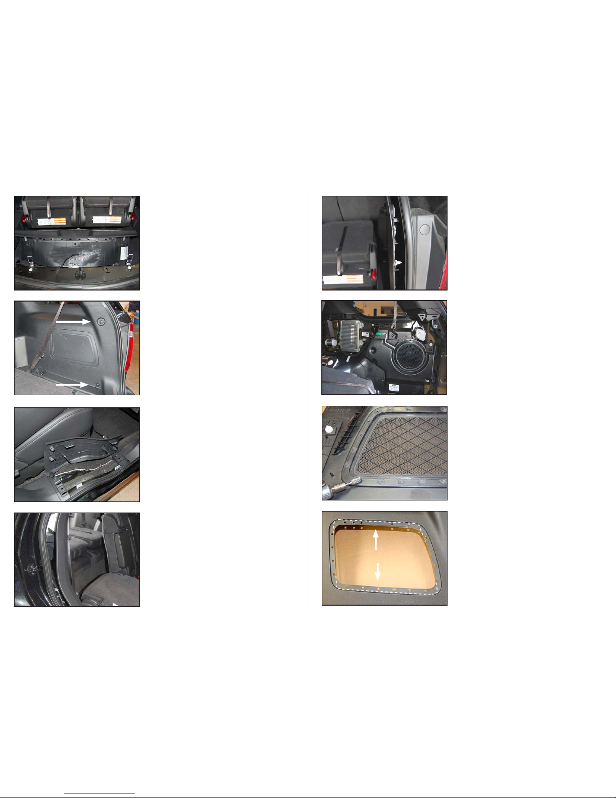
STEP 7
Begin unclippng the side panel, as shown.
STEP 6
Open the rear door on the passenger side. Carefully pull up
on the sill panel to release the clips, and remove the panel.
Remove the clip holding the side panel to the floor.
STEP 5
Unscrew the two hook s on the side panel.
STEP 4
Fold the seats back up, as shown. Carefully pull up on the
rear sill panel to release the clips. Unplug the harness, and
remove the panel.
Page 2 • JL Audio, Inc 2011
STEP 9
Pictured is the fac tor y subwoofer enclosure with the side
panel removed. Unplug the subwo ofer harness. Locate and
remove the three bolts holding in the enclosure, and remove
the enclosure from the vehicle.
STEP 11
Enlarge the grille opening on the side panel by cutting on
the indicated dotted lines. The top and bottom portions of
the grille opening need to be removed, but the sides will
remain.
STEP 10
Carefully grind through the plastic welds on the back of the
side panel to remove the grille from the panel.
STEP 8
Continue toward the rear of the vehicle, carefully releasing
the remaining side panel clips, and remove the panel.
Page 3
Continued on Next Page
SB-F-EXPL3/10W3v3 INSTR_SKU# 011325
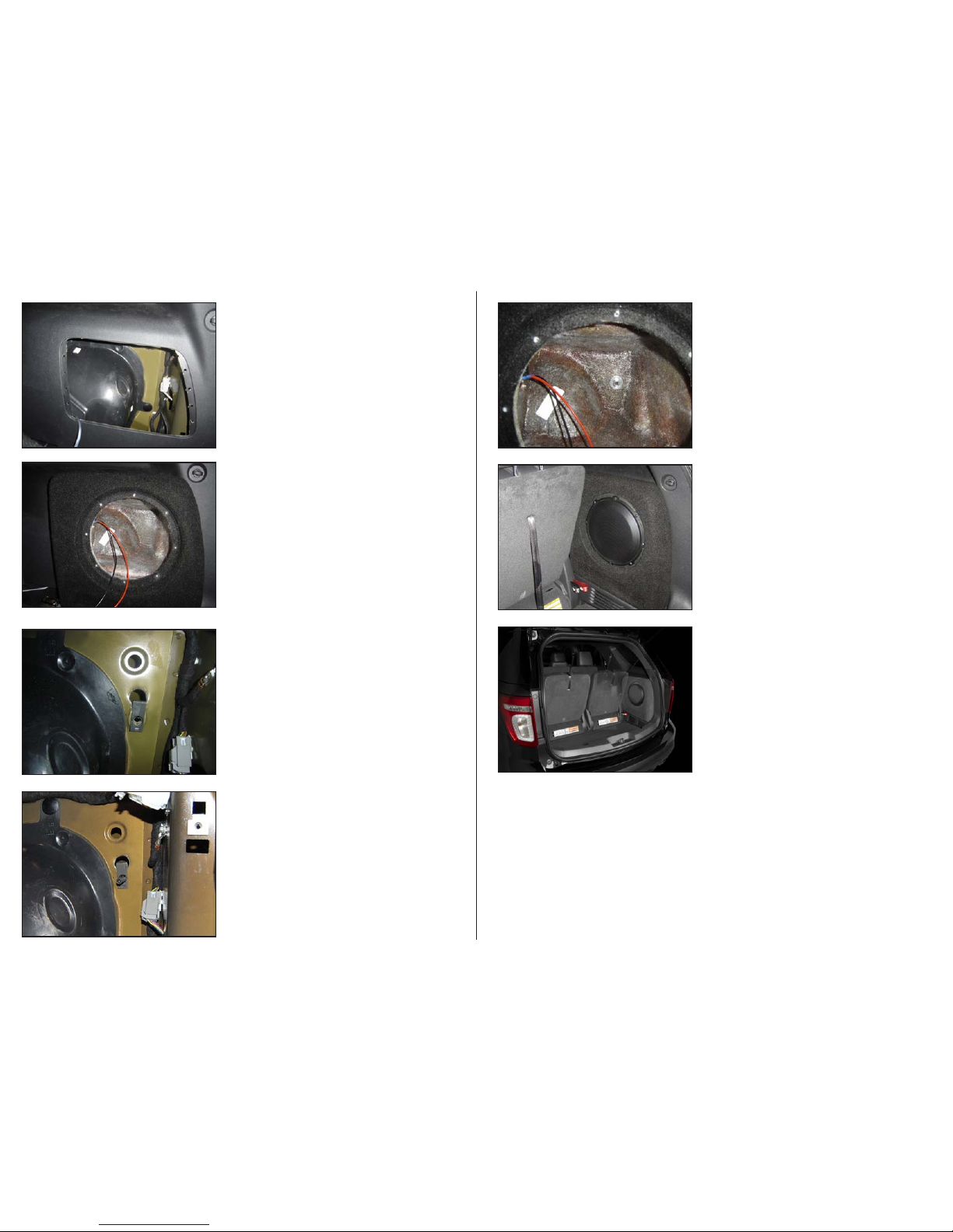
STEP 15
Thread the supplied 3/8 - 16 x 2-1/4” Set Screw into the
U-Nut, as shown.
STEP 14
Remove the Stealthbox® from the vehicle. Measure 1-1/8” up
from the center of the hole drilled in Ste p 13, and drill a 1”
hole. Slide the U-Nut through the 1” hole and align with the
smaller hole, as shown.
Before dril ling, always make sure that you ar e not
going to be drilling into any gas lines, brake lines,
tires, transmission lines, electrical wiring, exhaust
systems or any thing else that might ca use a
reducti on in your weekly pay.
Always wear eye protection when drilling!
STEP 13
Remove the subwoofer from the Stealthbox®, and place the
enclosure into position. Locate the hole in the back of the
enclosure. Using a 1/2” drill bit, drill through the hole and
into the metal panel behind the enclsoure.
Before dril ling, always make sure that you ar e not
going to be drilling into any gas lines, brake lines,
tires, transmission lines, electrical wiring, exhaust
systems or any thing else that might ca use a
reducti on in your weekly pay.
Always wear eye protection when drilling!
STEP 12
Route speaker cable to the Stealthbox® location, and reinstall
the side panel back into the vehicle. Pic tured is the panel in
place after it has been cut as indicated in S tep 11.
Page 3 • JL Audio, Inc 2011
STEP 17
Reinstall the upper hook, the two sill panels, the seat belt
bolt, and the small trim panel.
CONGRATULATIONS!
You have completed the installation for this model!
Enjoy your new Stealthbox®!
Please refer to the Power Recommendation se ction for an
amplifier recommendation and basic set-up help.
STEP 16
Attach the speaker cable to the Stealthbox®, and place the
enclosure back into position allowing the 3/8 - 16 x 2-1/4” Set
Screw to slide through the hole in the back of the enclosure.
Place a 3/8” x 1-1/4” Fender Washer, a 3/8” Lock Washer, and
a 3/8” - 16 Hex Nut over the 3/8 - 16 x 2-1/4” Set Screw, and
firmly tighten. Reinstall the suboofer.
Page 4
SB-F-EXPL3/10W3v3 INSTR_SKU# 011325
Page 4• JL Audio, Inc 2011
All specifications are subject to change without notice. “JL Audio®” and the JL Audio logo, “Stealthbox” and the Stealthbox logo are registered
trademarks of JL Audio, Inc. “Ahead of the Curve” and its respective logo is a trademark of JL Audio, Inc.
JLA-SKU# 94520 07.29.2011 • Printed in USA • ©2008 JL Audio, Inc. • U.S. PATENTS: #5,734,734 #5,949,898 #6,118,884 #6,229,902 #6,243,479
#6,294,959 #6,501,844 #6,496,590 #6,441,685 #5,687,247 #6,219,431 #6,625,292 #D472,891 #D480,709 Other U.S. & Foreign patents pending.
For more detailed information please visit us online at www.jlaudio.com.
(954) 443-1100
www.jlaudio.com
10369 NORTH COMMERCE PARKWAY • MIR AMAR, FLORIDA • 33025 • USA
INCLUDED HARDWARE
(1) U-Nut (1) 3/8” Split Lock Washer
(1) 3/8-16 x 2-1/4” Set Screw (1) 3/8” -16 Hex Nut
(1) 3/8” x 1-1/4” Fender Washer
SPECIFICATIONS
Enclosure Type: Acoustic Susp ension (sealed)
Driver Type: 10W 3v3
Nominal Impedance: 2 ohm
Continuous Power Handling: 500 watt s
POWER RECOMMENDATION
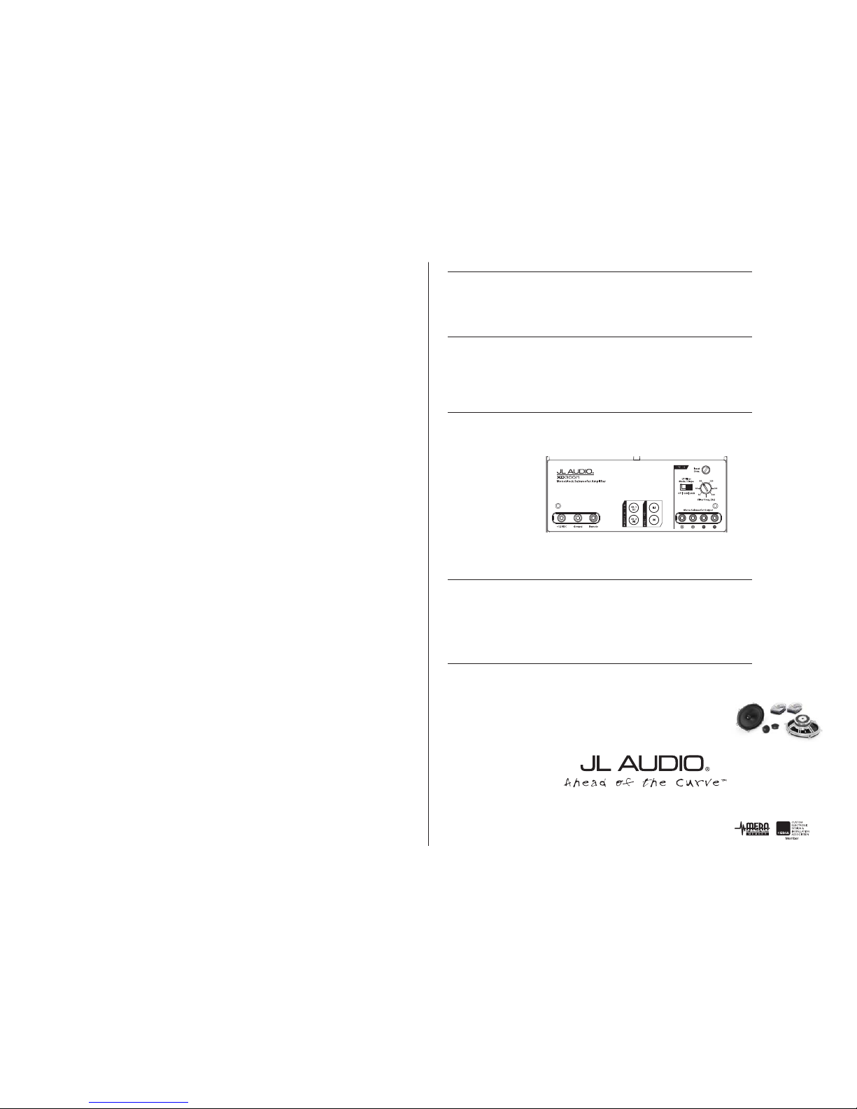
JL Audio recommends high quality amplif iers such as the JL Audio XD700/5 or XD300/1. The diagram below
shows the recommende d crossover settings for the XD300/1 . If another amplifier is being used, please reference
this illustration and use similar set tings on that amplifier.
All JL Audio amplifiers are very versatile audio components. Please consult the owner’s manual for even more
detailed information about installing and tuning your amplifier.
CONNECTIONS
Using quality power, signal, and speaker wire is essential in ensuring the performance of your Stealthbox®.
JL Audio recommends using a 4 AWG power k it such as the XD-PCS4-1B for your Stealthbox® amplifi er. Other
kits are available sho uld you be using more than one amplifier. Signal wire such as the JL Audio Premium Audio
Interconnect Cables sho uld be used to provide signal for both channels of the amplifier. JL Audio reccommen ds
using 12AWG speaker wire for subwoofers such as our XC-BCS12-25.
MID/HIGH FREQUENCY DRIVER FITMENT
A variety of JL Audio coa xial and component systems will fit in the f actory speaker locations of you vehicle.
Front Speaker Size / Location: 5”x 7” / 6”x 8”- Front Doors
Fits JL Audio Models: TR570-CX i, C2-570x , C3-570, C5-570, C5 -570x & ZR570 -CSi
Rear Speaker Size / Location: 5”x 7” / 6”x 8”- Rear Door
Fits JL Audio Models: TR570-CX i, C2-570x , C3-570, C5-570, C5 -570x & ZR570 -CSi
 Loading...