

Page 1
SB-F-EDG/10W3v3 INSTR_SKU# 011254
I N S T A L L A T I O N G U I D E
for the
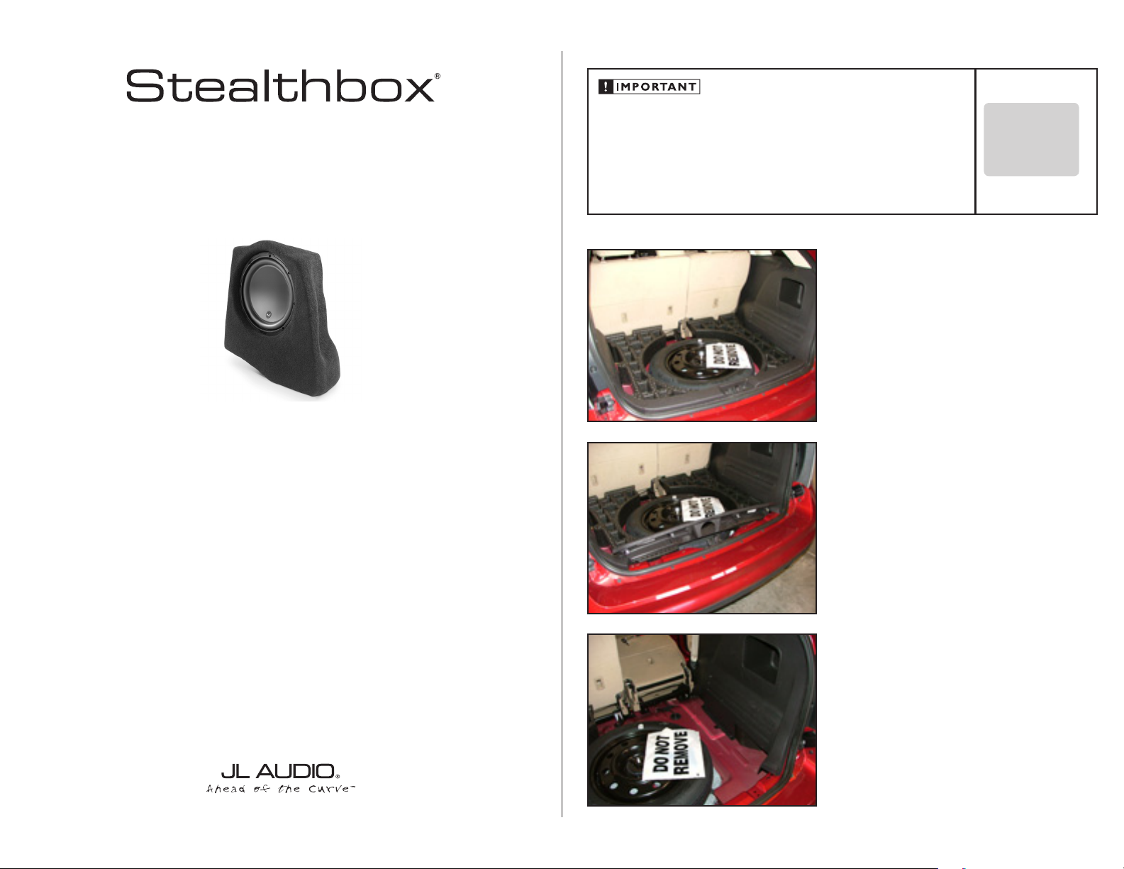
SB-F-Edg/10W3v3
SKU#94376
2007+ Ford Edge
Thank you for choosing a JL Audio Stealthbox® for your automotive sound system. With proper
installation, your new vehicle-specific enclosed subwoofer system will deliver years of listening pleasure.
If you choose to perform the installation yourself, it is absolutely vital that
the Stealthbox® be properly mounted to the vehicle according to these
instructions. Failure to mount the enclosure properly presents two problems:
1) The sub-bass performance will suffer due to the movement of the enclosure
caused by the force exerted by the woofer(s).
2) A loose enclosure presents a serious safety hazard in the event of a collision
or sudden deceleration.
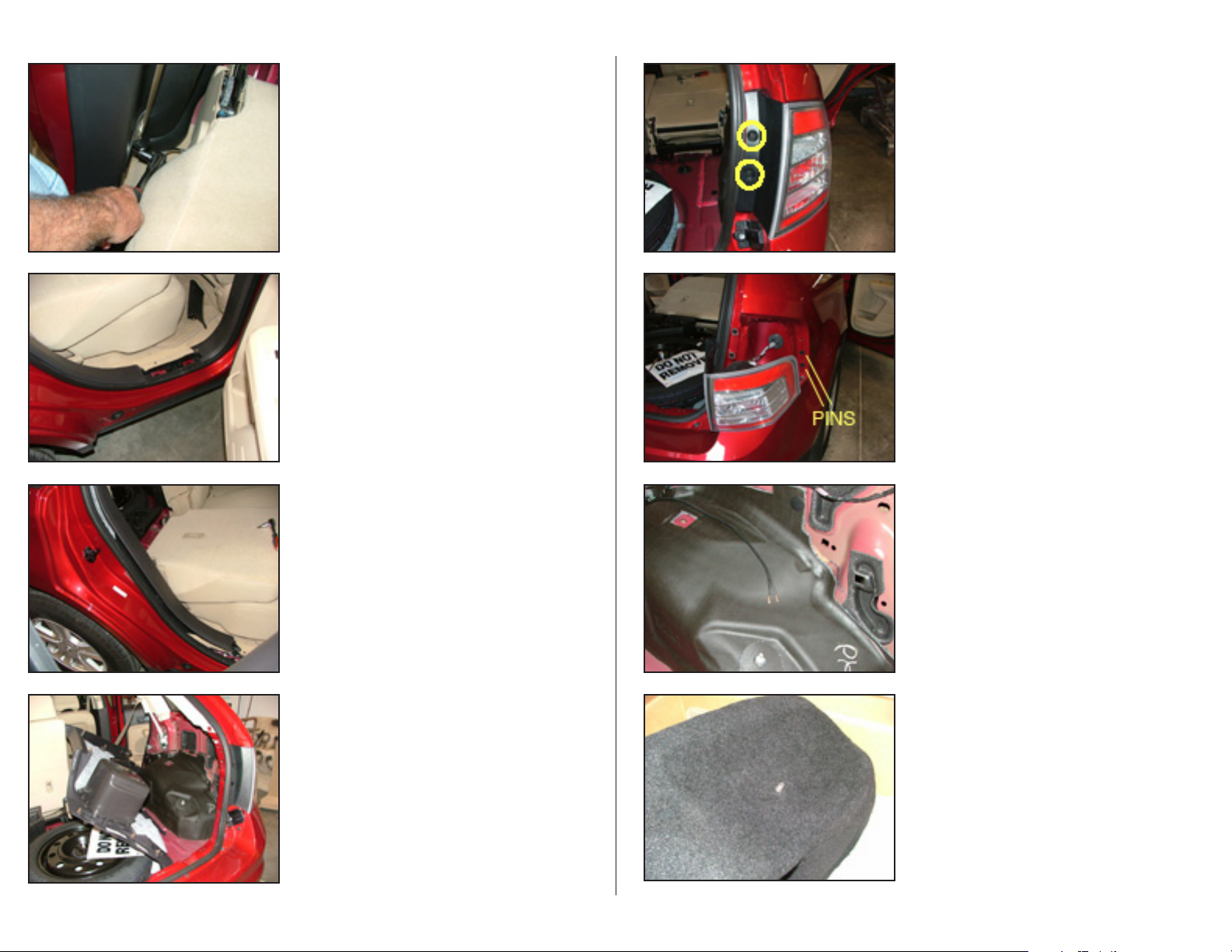
S T E P 1
Remove the floor panel by lifting seat flaps. Carefully tilt
entire panel to exit hatch diagonally.
S T E P 2
Remove threshold plate by lifting directly upward.
INSTALLATION
D I F F I C UL T Y:
OU T
OF
35
ESTIMATED TIME:
23 HO URS
We strongly recommend that you have your new Stealthbox® installed by your authorized JL Audio
dealer. The installation professionals employed by your dealer have the necessary tools and experience
to disassemble and reassemble your vehicle properly. Also, keep in mind that your warranty coverage
extends to 2 years if your system is installed or approved by your authorized JL Audio dealer. If you
prefer to perform your own installation, please read this installation guide completely
before beginning the process.
S T E P 3
Remove foam filler panel from passenger side of spare tire.
Continued on Next Page
Page 2
SB-F-EDG/10W3v3_INSTR_SKU# 011254
S T E P 4
Fold passenger side rear seat forward.
Remove bolt securing seat belt at lower front of cargo
side panel.
S T E P 5
Remove passenger side threshold plate.
S T E P 6
Pull passenger side cargo panel away from the door jamb.
S T E P 8
Remove passenger side taillight assembly by removing
(2) 8mm screws.
S T E P 9
Carefully pry taillight assembly out, then back, from vehicle,
releasing two alignment pins at the front edge.
Remove bulbs from assembly by turning 1/4 turn to the left.
S T E P 1 0
Route woofer wiring to passenger side rear of cargo area.
Page 2 • JL Audio, Inc 2008
S T E P 7
Remove passenger side cargo panel by prying away from
side of vehicle and floor.
S T E P 1 1
Unpack Stealthbox® and install mounting stud into threaded
insert so that 1/2 to 3/4 inch extends from enclosure.
Continued on Next Page
Page 3

SB-F-EDG/10W3v3_INSTR_SKU# 011254
STEALTHBOX WALL
VEHICLE SHEET METAL
THREADED INSERT
LOCK WASHER
FLAT WASHER
SOCKET CUP SET SCREW
HEX NUT
FENDER WASHER
S T E P 1 2
Remove backing from wax square and place it on sheet
metal just below tail light wiring as shown.
S T E P 1 3
Place Stealthbox® into location as shown, push stud against
wax square to make an impression in the wax square.
S T E P 1 4
Remove Stealthbox®. Drill 1/2 inch diameter hole through
wax square and sheet metal at stud impression.
S T E P 1 6
Put Stealthbox® into final position with mounting stud
extended through hole drilled in tail light area. Secure with
nut, lock washer, and flat washer provided (see illustration).
S T E P 1 7
Position the Stealthbox® into the mounting location. From
the outside of the vehicle (behind the taillight) place the supplied fender washer, flat washer, lock washer and then nut
onto the exposed socket cup set screw. Use a long 3/8" open
end wrench or ratcheting box end to secure the mounting
hardware. Be sure Stealthbox is now solidly mounted to
vehicle.
Note : For added weather protection, it is recommended
that you apply a bead of silicone between the vehicle
and the fender washer.
S T E P 1 8
Connect the previously run wire to the Stealthbox® and test
the system to ensure that everything sounds good so far.
Page 3 • JL Audio, Inc 2008
Remove the wax square.
it is recommended that vehicle undercoating be applied
where the mounting hole was drilled.
S T E P 1 5
Extend mounting stud 1 1/2 inch from enclosure.
S T E P 1 9
Reinstall taillight in reverse oder of removal as detailed in
steps 9,8. Make sure that bulbs go into the right locations
in the lens assembly by checking the brake lights, running
lights and, reverse lights. Be carefull of alignment of pins as
lens assembly is reinserted into fender recess. Secure mounting with the factory 8mm screws.
Continued on Next Page
Page 4

SB-F-EDG/10W3v3_INSTR_SKU# 011254
S T E P 2 0
Place cargo side panel onto a flat surface with back side up.
Locate back side of storage compartment. Carefully grind
heads of plastic spot welds to allow removal of compartment
enclosure. Take care not to damage front of panel.
S T E P 2 1
Remove storage compartment from side panel.
S T E P 2 2
Using provided grill as a guide, mark the required grill opening onto the side cargo panel with grease pencil or masking
tape. Cut out opening to allow fitment of grill with maximum
open area.
S T E P 2 4
Drill 1/8 inch holes as indicated on template.
S T E P 2 5
Install grille with short #8 screws and #8 flat washers as
provided.
S T E P 2 6
Step backwards through steps 7- 1, installing side cargo
panel, side threshold plate, rear seat belt bolt, rear threshold
plate and floor as removed.
C O N G R A T U L A T I O N S !
You have completed the installation for this model!
Page 4 • JL Audio, Inc 2008
Enjoy your new Stealthbox®!
Please refer to the Power Recommendation section for an
amplifier recommendation and basic set-up help.
S T E P 2 3
Position provided grille template on front of side of cargo
panel so as to cover storage pocket opening and, align with
horizontal ridges below. Tape into place.
Continued on Next Page
Page 5

SB-F-EDG/10W3v3_INSTR_SKU# 011254
I N C L U D E D H A R D W A R E
(1) wax square (8) #8x 3/8” Pan head phillips screws
(1) 3/8-16 X 2.25 set screw stud (8) #8 SAE Flat Washer
(1) 3/8 X 2 fender washer
(1) 3/8 lock washer
(1) 3/8 X 1.25 nut
(1) grill panel template
S P E C I F I C A T I O N S
Enclosure Type: Acoustic Suspension (sealed)
Driver Type: 10W3v3-4
Nominal Impedance: 4 ohms mono
Continuous Power Handling: 500 Watts
P O W E R R E C O M M E N D A T I O N
JL Audio recommends using a high quality amplifier such as the JL Audio 250/1v2.
The diagram below shows the recommended crossover, infrasonic filter and equalizer settings for the 250/1v2
when being used to power your Stealthbox®.
Page 5• JL Audio, Inc 2008
The JL Audio 250/1v2 is a very versatile audio component. Please consult the owner’s manual for even more
detailed information about installing and tuning this amplifier.
M I D / H I G H F R E Q U E N C Y D R I V E R F I T M E N T
A variety of JL Audio coaxial and component systems will fit in the factory speaker locations of you vehicle.
Front Speaker Size / Location: 5”x 7” / 6”x 8”- Front Doors
Fits JL Audio Models: TR570-CXi, C5-570, C5-570x & ZR570-CSi
Rear Speaker Size / Location: 5”x 7” / 6”x 8”- Rear Door
Fits JL Audio Models: TR570-CXi, C5-570x
(954) 443-1100
All specifications are subject to change without notice. “JL Audio®” and the JL Audio logo, “Stealthbox” and the Stealthbox logo are registered
trademarks of JL Audio, Inc. “Ahead of the Curve” and its respective logo is a trademark of JL Audio, Inc.
JLA-SKU# 011254 3-19-2008 • Printed in USA • ©2007 JL Audio, Inc. • U.S. PATENTS: #5,734,734 #5,949,898 #6,118,884 #6,229,902 #6,243,479
#6,294,959 #6,501,844 #6,496,590 #6,441,685 #5,687,247 #6,219,431 #6,625,292 #D472,891 #D480,709 Other U.S. & Foreign patents pending.
For more detailed information please visit us online at www.jlaudio.com.
1 0 3 6 9 N O R T H C O M M E R C E P A R K W A Y • M I R A M A R , F L O R I D A • 3 3 0 2 5 • U S A
w w w. j l a u d i o . c o m
 Loading...