

JL Audio SB-D-TRKEXT-10W1v2-GA, SB-D-TRKEXT-10W1, SB-D-TRKEXT-10W1v2-MT, SB-D-TRKEXT-10W1v2-BK User Manual
Page 1
➔
➔
Stealthbox
®
INSTALLATION GUIDE
SB-D-TRKEXT/10W1, JL AUDIO, Inc 2004
Sheet SKU#011105 Revision6/28/2004 Page 1
for the
SB-D-TRKEXT/10W1
(Dodge Ram
‘94-’01 1500 Club Cab,
‘98-’01 1500 Quad Cab,
‘94-’02 2500 Club Cab,
‘98-’02 2500 Quad Cab,
‘95-’02 3500 Club Cab,
‘98-’02 3500 Quad Cab)
This Stealthbox is a product which
requires professional installation skills and
tools.
Please read this installation guide thoroughly before beginning the project. It
will guide you step by step through the
installation. Several of the steps in this
process may require two people to
accomplish.
It is absolutely vital that the enclosure
be properly mounted to the vehicle
according to these instructions. Failure
to mount the enclosure properly presents two problems: 1) The sub-bass
performance will suffer due to the
movement of the enclosure caused by
the force exerted by the woofer(s) and
2) A loose enclosure presents a serious
safety hazard in the event of a collision
or sudden deceleration.
Please enjoy your JL Audio Stealthbox
responsibly.
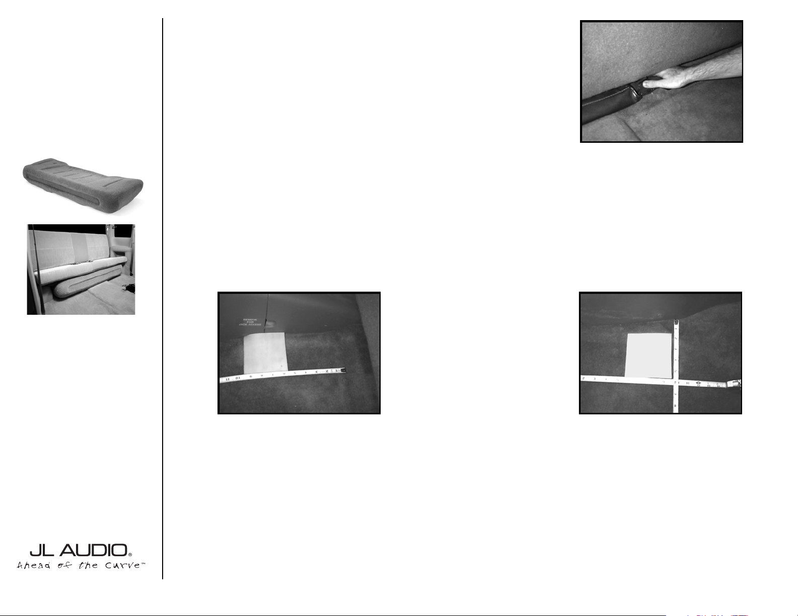
STEP 1:
Slide the front seats all the way for-
ward and fold-up the rear bench seat.
STEP 2:
Under the rear bench seat, there are
a pair of metal brackets which hold the tire
changing tools. Bend these up and back so
they are out of the way of then enclosure.
STEP 3:
Place one of the two supplied wax
squares to this location(remove paper, sticky
side down).
The outside edge of the wax square needs to
be flush with the jack storage compartment.
The rear edge needs to be 5-1/2” from the
ledge at the back of the cab floor.
STEP 4:
Place the other supplied wax square
to this location. (remove paper, sticky side
down).
The rear edge needs to be 5-1/2” from the
back of the cab.The inside of the wax square
needs to be 5-1/2” from the outside edge of
the carpet.
START
HERE
Continued on Next Page ➔
www.jlaudio.com
➔
➔
Page 2

➔
➔
STEP 5:
Insert the supplied pair of socket
cup set screws into the threaded inserts of
the bottom of the enclosure. Leave 1/2”
exposed.
Cont.
From
Previous
Page
Continued on Next Page ➔
➔
STEP 8: *Double check under the truck
for brake lines, fuel lines or any other wiring.
*
Using a drill and a 1/2” drill bit. Drill at the impression on the wax squares as a guide.
STEP 9: Double check the woofers for proper
functioning.
Run speaker wire to the enclosures mounting location and secure it to the wire terminal on the enclosure.
STEP 6:
With the help of a second person,
place the enclosure into the truck and position it in the mounting location. Once in
place, firmly press down onto the enclosure.
You can even sit on it.This is allowing the
socket cup set screws to leave an impression
onto the wax squares.
STEP 7: Remove the enclosure from the
truck. Make sure that the wax square stay
adhered to the carpet. Also back out the
socket cup set screws to expose 1-1/2”.
SB-D-TRKEXT/10W1, JL AUDIO, Inc 2004.
Sheet SKU#011105 Revision6/28/2004 Pag e 2
www.jlaudio.com
➔
Page 3
Specifications:
Enclosure Type: Acoustic Suspension (Sealed)
Driver Type: (2)10W1-8
Nominal Impedance: 4Ω
Cont. Power Handling: 250Watts
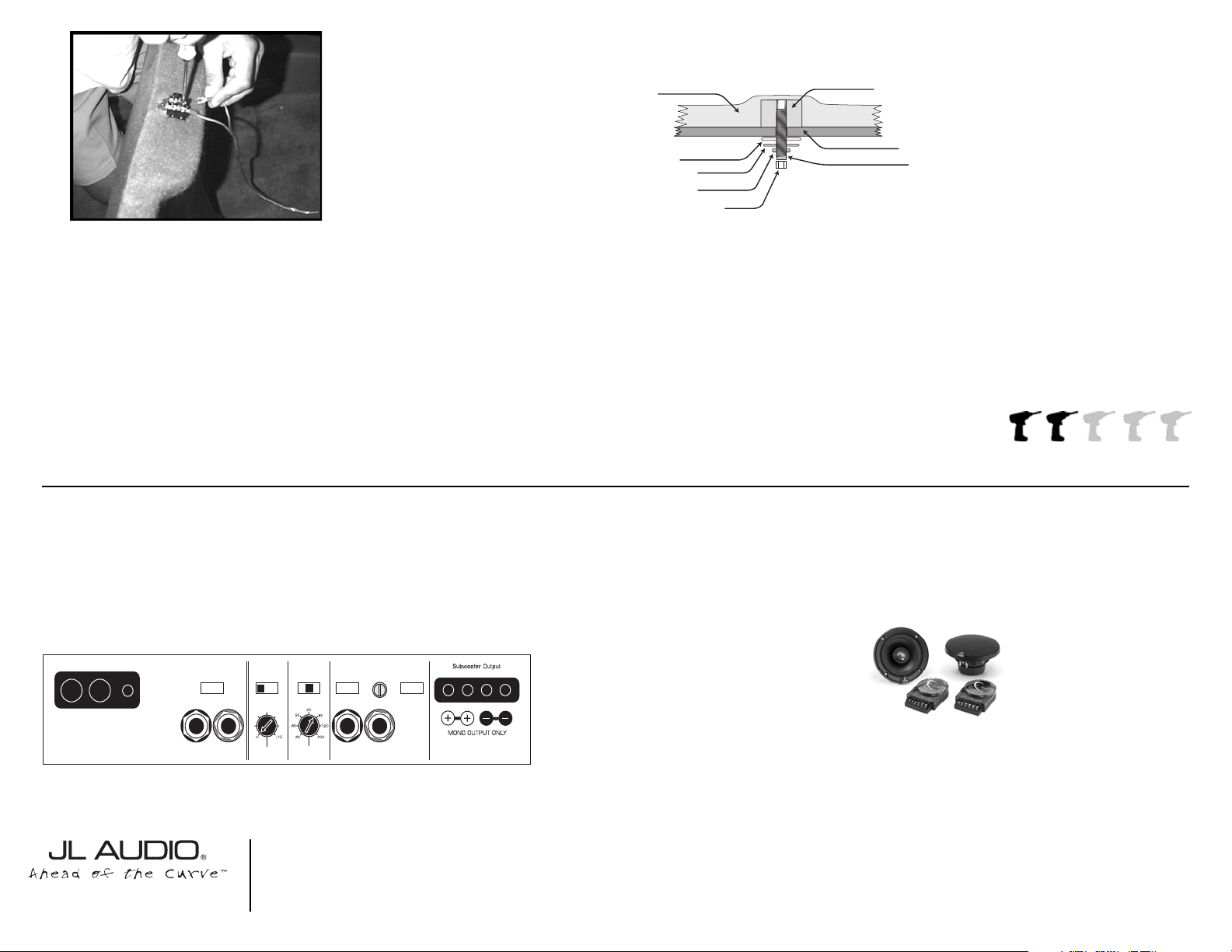
JL Audio recommends using a high quality amplifier such as the JL Audio 250/1. The diagram below shows the recommended
crossover, infrasonic filter and equalizer settings for the 250/1 when being used to power your Stealthbox®.
Included Hardware:
(2) 3/8”-16 X 2-1/4” Socket Set Screw
(2) 3/8” Fender Washers
(2) 3/8” Flat Washer
(2) 3/8” Lock Washer
(2) 3/8’-16 Hex Nut
10369 N. Commerce Pkwy, Miramar, Florida 33025-392 Phone: 954.443.1100 Fax: 954.443.1111
+12VDC Ground Remote
The JL Audio 250/1 is a very versatile audio component. Please consult the owner’s manual for detailed information
about installing and tuning this amplifier.
➔➔➔
STEP 9: Double check the woofers for proper
functioning.
Run speaker wire to the enclosures mounting location and secure it to the wire terminal on the enclosure.
STEP 10: Place the enclosure back into the
mounting location Line up and guide the two socket
cup set screws through the drilled holes from
STEP 8.
STEP 11: With the supplied hardware, place as in
order of direction.
Place the fender washer, flat washer, lock washer and
then hex nut onto the protruding socket cup set
screws.
Adjust the socket cup set screws for more or less
threads that are needed. Hand tighten the nuts, till
both mounting assemblies are on.
Tighten securely.
➔
SB-D-TRKEXT/10W1, JL AUDIO, Inc 2004
Sheet SKU#011105 Revision6/28/2004 Pag e 3
www.jlaudio.com
Mid/High Frequency Driver Information:
CONGRATULATIONS!
INSTALL COMPLETE.
XR525-CXi
Front Location Driver Size:
6”x9”
Applicable JL Audio Products:
N/A
Rear Location Driver Size:
5.25”
Applicable JL Audio Products:
TR,VR,XR525-CXi
Cont.
From
Previous
Page
Difficulty Of Installation:
STEALTHBOX WALL
THREADED INSERT
FENDER WASHER
FLAT WASHER
LOCK WASHER
HEX NUT
VEHICLE SHEET METAL
SOCKET CUP SET SCREW
Bass Control
Infrasonic Filter
Off/30Hz
+7
+3
+1
LF Boost (dB)
+10
+13
Amp LP Filter
Mode/Slope
Off/12dB/24dB
Filter Freq. (Hz)
Amplifier Input Section
Input Voltage
Input Sens.
Low/High
Left Ch.
Right Ch.
Signal Sensing
Off/On
JL AUDIO 250/1
monoblock subwoofer amplifier
Preamp Output Section
Output Mode
Full-Range/Low-Pass/High-Pass
Left Ch.
Right Ch.
 Loading...