

Page 1

INSTALLATION GUIDE
for the
SB-CAN-MVX3/10TW3
SKU# 94646
2017 & Up Can-Am Maverick X3 (2-seat)
Thank you for choosing a JL Audio Stealthbox® for your automotive sound system.
With proper installation, your new vehicle-specific enclosed subwoofer system
will deliver years of listening pleasure.
We strongly recommend that you have your new Stealthbox® installed by your
authorized JL Audio dealer. The installation professionals employed by your
dealer have the necessary tools and experience to disassemble and reassemble
your vehicle properly. If you prefer to perform your own installation, please read
this installation guide completely before beginning the process.
If you choose to per form the installation yoursel f, it is abso lutely
vital that the Stealthb ox
®
be properly mo unted to the vehicle
according to these instr uctions. Failure to mount the enclosure
properly presents two problems:
1) The sub-bass perfor mance will suffer due to the movement of th e
enclosure caused by the force exerted by the woofer(s).
2) A loose enclosure present s a serious safety hazard in th e event of a
collision or sudden deceleration.
INSTALLATION
DI FFIC ULT Y:
ESTIMATED TIME:
2 HOURS
Enclosure Type: Sealed
Driver Type: 10TW3-D4
Nominal Impedance: 2 ohms
Continuous Power Handling: 400 watts (RMS method)
Continued on Next Page
2
5
OUT
OF
SB- CAN-MVX3/10TW3 INSTR_SKU# 011492
Page 2
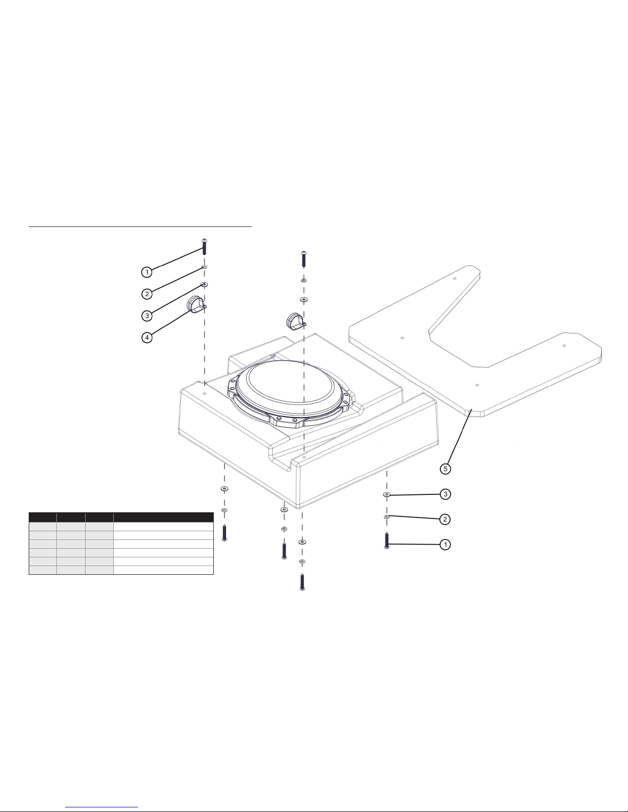
INCLUDED HARDWARE
Continued on Next Page
Page 2 • JL Audio, Inc., 2017
SB- CAN-MVX3/10TW3 INSTR_SKU# 011492
BOM ID Qty SKU Description
1 6 151709 1/4 - 20 x 1-1/2” Socket Cap Screw
2 6 150066
1/4” Split Lock Washer
3 6 153734 1/4” Flat Washer
4 2 153764 Stainless Steel Cushion Clamp
5 1 152431 Template
- 1 150249 Foam Tape (not shown)
Note: For optimum p erformance, JL Audio recomme nds applying the included Foa m Strips (or sound damping material) to surro unding plastic panels to redu ce unwanted vibrations.
Page 3

POWER RECOMMENDATION
JL Audio recommends high quality amp liers such as the JL Audio MX300/1. The diagram below shows the recommended crossover settings for the MX300/1. For a detailed description of the
amplier settings, consult the own er’s manual for the amplier. If another amplier is being used, please reference this illustration and use similar settings on that amplier.
CONNECTIONS
Using quality power, signal, and speaker wire is essential in ensuring the p erformance of your Stealthbox®. JL Audio recommends using a 4 AWG power kit such as the XD-PCS4-1B for your
Stealthbox® amplier. Other kits are available should you be using more than one amplier. Signal wire such as the JL Audio Premium Audio Interconnect Cables sh ould be used to provide signal for
both channels of the amplier. JL Audio recommends using 12AWG speaker wire for subwoofers such as our XC-BCS12-25.
Continued on Next Page
Page 3 • JL Audio, Inc., 2017
SB- CAN-MVX3/10TW3 INSTR_SKU# 011492
Page 4

Page 4 • JL Audio, Inc., 2017 Continued on Next Page
STEP 8
Remove the Template from the vehicle.
Using a 1/8” drill bit, drill a pilot hole through
each of the marks made in the previous step.
STEP 7
Using a small pick tool, mark each of the hole
locations through the Template onto the
plastic floor panel.
STEP 6
Position the Template on the vehicle floor. Push
the Template forward and to the outside, as
shown, until flush with the frame rails.
STEP 5
Unplug the seat belt wiring harness.
Carefully remove the driver’s seat from the
vehicle.
STEP 4
Remove the seat belt bolt.
STEP 3
Slide the driver’s seat forward.
Remove the two rear seat bolts from the seat
bracket.
STEP 2
Remove the two front seat bolts from the
driver’s seat bracket.
STEP 1
Empty the front of the vehicle.
SB- CAN-MVX3/10TW3 INSTR_SKU# 011492
Page 5

Page 5 • JL Audio, Inc., 2017 Continued on Next Page
ST EP 16
Slide a 1/4” Split Lock Washer and a 1/4” Flat
Washer over each of four 1/4 - 20 x 1-1/2”
Socket Cap Screws.
From under the vehicle, pass each assembly
through a drilled hole in the floor panel, into a
threaded insert in the bottom of the enclosure,
and fully tighten.
ST E P 15
Tighten the eight subwoofer mounting screws.
ST E P 14
Push the enclosure forward, allowing it to drop
into position. Place the subwoofer back into
the enclosure.
ST E P 13
Partially lift the subwoofer out of the enclosure,
as shown. This allows for clearance to position
the enclosure in the next step.
ST E P 12
Carefully set the enclosure into the vehicle, as
shown.
STE P 11
Completely loosen the eight subwoofer
mounting screws, but do not remove them.
ST EP 10
Place the Stealthbox® face down on a flat
surface. Attach Foam Tape to the bottom of the
enclosure, as shown.
STEP 9
Using a 5/16” drill bit, enlarge each of the pilot
holes drilled in the previous step.
SB- CAN-MVX3/10TW3 INSTR_SKU# 011492
Page 6

Page 6 • JL Audio, Inc., 2017
CONGRATULATIONS!
You have completed the installation for this model! Enjoy your new Stealthbox®!
SB- CAN-MVX3/10TW3 INSTR_SKU# 011492
MID/HIGH FREQUENCY DRIVER FITMENT
VeX™ Enclosed Speaker Sys tems are ideal for powersport s and o-road vehicle applica tions. Each
weatherproof p od can be mounted to a roll cage precis ely aimed for optimum sound. M ounting
xtures are availa ble to t a variety of roll cage dia meters.
(954) 443-1100
www.jlaudio.com
JLA-SKU# 011492 • ver. 06.19.2017 • 10369 NORTH COMMERCE PARKWAY • MIRAMAR, FLORIDA • 33025 • USA
All specifications are subject to change without notice. “JL Audio®” and the JL Audio logo, and “Stealthbox” and the Stealthbox logo are registered trademarks of JL Audio, Inc. “Ahead of the
Curve”, its respective logo, and “How we play” are trademarks of JL Audio, Inc.
Printed in USA • ©2016 JL Audio, Inc. • For more detailed information please visit us online at www.jlaudio.com.
STEP 20
Pictured is the Stealthbox® completely secured.
Connect speaker cable to the barrier strip on
the back of the enclosure, and route the cable
as necessary.
ST EP 19
Repeat the process for the outside front frame
rail position.
Fully tighten both 1/4 - 20 x 1-1/2” Socket Cap
Screws.
ST EP 18
Wrap a Stainless Steel Cushion Clamp over the
inside front frame rail, aligning its holes with
the threaded insert in the top of the enclosure.
Slide a 1/4” Split Lock Washer and a 1/4” Flat
Washer over a 1/4 - 20 x 1-1/2” Socket Cap
Screw, pass the assembly through the holes in
the Stainless Steel Cushion Clamp, and into the
threaded insert.
ST EP 21
Carefully reinstall the driver’s seat.
Connect the seat belt harness, reinstall the seat
belt bolt, the two rear seat bolts, and the two
front seat bolts.
Note: For optimum performance, we
recommend applying the included Foam Strips
(or sound damping material) to surrounding
plastic panels to reduce unwanted vibrations.
 Loading...