

JL Audio SB-B-X5E70, Stealthbox SB-B-X5E70/10W3v3 Installation Manual
INSTALLATION GUIDE
for the
SB-B-X5E70/10W3v3
SKU# 94517
2007 -Up BMW X5
Thank you for choosing a JL Audio Stealthbox® for your automotive sound system. With proper installation, your new
vehicle-specific enclosed subwoofer system will deliver years of listening pleasure.
We strongly recommend that you have your new Stealthbox® installed by your authorized JL Audio dealer. The
installation professionals employed by your dealer have the necessary tools and experience to disassemble and
reassemble your vehicle properly. Also, keep in mind that your warranty coverage extends to 2 years if your system is
installed or approved by your authorized JL Audio dealer. If you prefer to perform your own installation, please read
this installation guide completely
before beginning the process.
If you choose to per form the installation yoursel f, it is abso lutely vital that
the Stealthbox
®
be properly mounted to the vehicle accord ing to these
instructions . Failure to mo unt the enclosure properly present s two problems:
1) The sub-bass per formance will suffer due to the movem ent of the enclosure
caused by the force exe rted by the woofer(s).
2) A loose enclosure pres ents a serious safety haza rd in the event of a collision
or sudden deceleration.
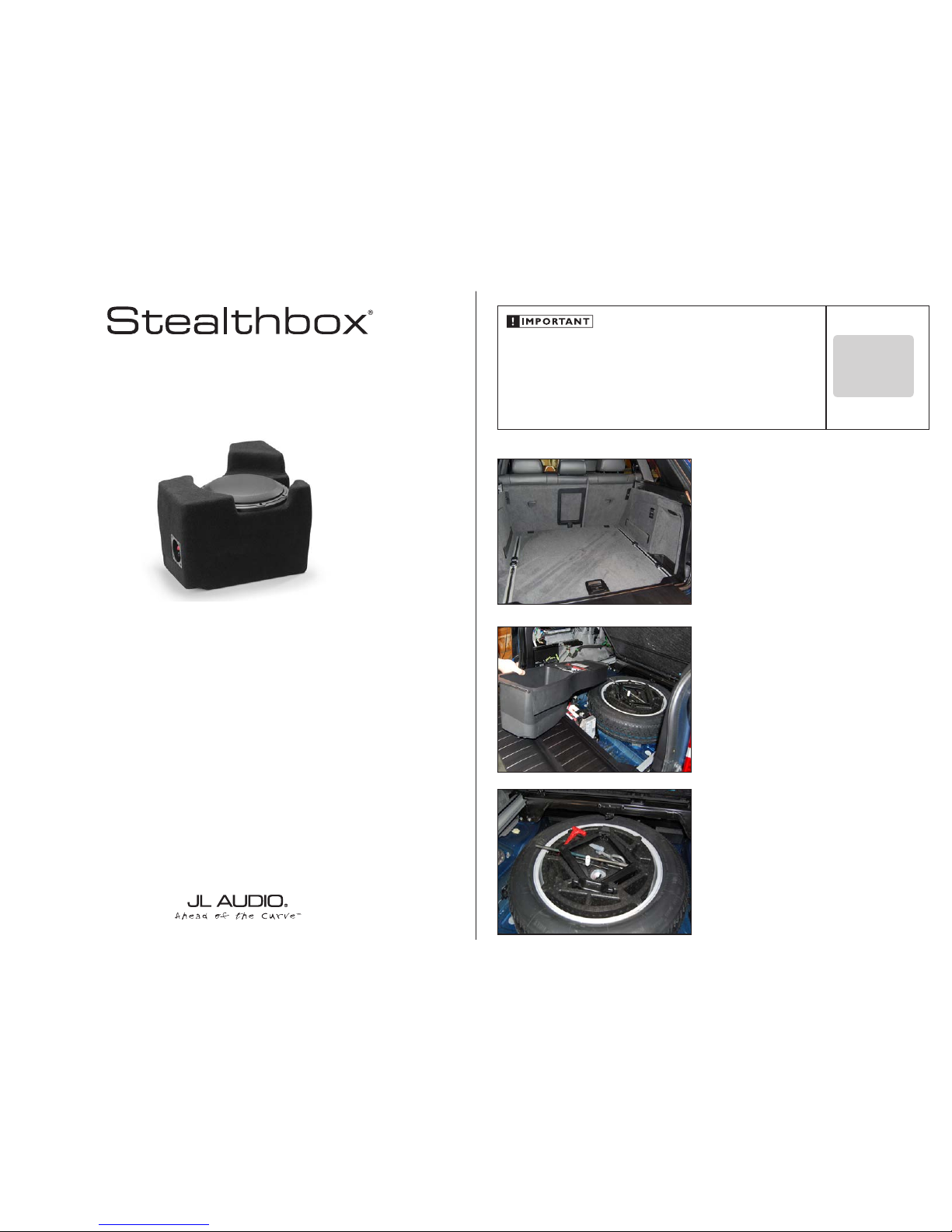
STEP 1
Empty out the cargo area so that you have a clean area to
work in.
Continued on Next Page
STEP 2
Remove the three screws on the b attery cover, and remove
the cover. Remove the screws holding in the storage tray,
and remove the tray.
STEP 3
The tools can be relocated to the foam tray inside the spare
tire.
SB-B-X5E70/10W3v3 INSTR_SKU# 011324
IN STALL ATIO N
DIFFICULTY:
25
OUT
OF
ESTIMATED TIME:
1 HOU R
Continued on Next Page
SB-B-X5E70/10W3v3 INSTR_SKU# 011324
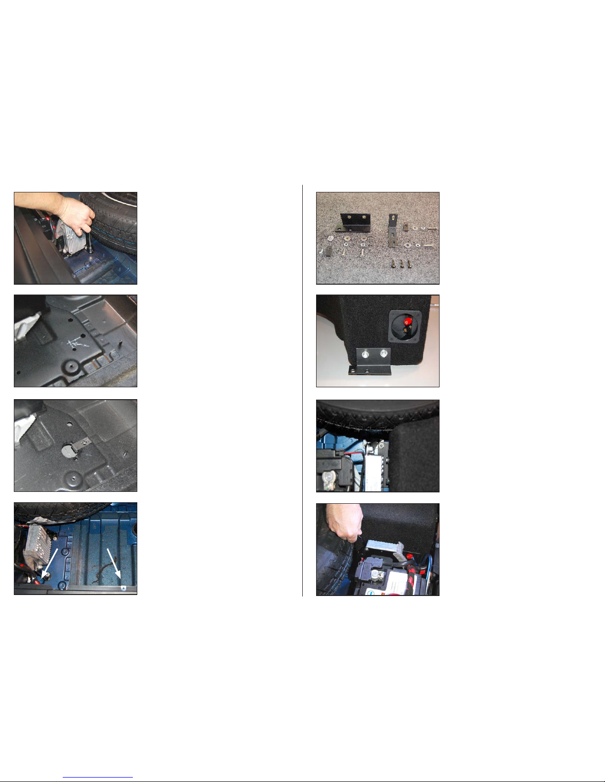
STEP 7
Remove the speed clip from the location indicated by the
left arrow, and relocate it to the location indicated by the
right arrow, as shown.
STEP 6
Using a 1” hole saw, drill a hole at the intersection, and slide
a U-Nut through the driled hole, aligning it with the f actory
hole, as shown.
STEP 5
Note: Steps 5-6 are only necessar y on vehicles not
equipped with the f actory bracket shown in Step 4.
Locate the two holes in the floor, and mark their
perpindicular intersection, as shown.
STEP 4
Remove the nut from the factory bracket, as shown. Retain
the nut for use in St ep 10.
If this factory bracket isn’t present, substitute Steps 5- 6.
Page 2 • JL Audio, Inc 2011
STEP 9
Using a pair of 1/4” - 20 x 1” Bolts, 1/4” Lock Washers, and 1/4”
Flat Washers, attach the Side Bracket to the Stealthbox® as
shown, and hand tighten.
STEP 8
Pictured is the included hardware, along with the fac tory nut
removed from Step 4.
STEP 10
Attach speaker cable to the Stealtbhox®, and place the
enclosure into position, aligning the hole in the Side Bracket
with the factor y bolt, as shown. Secure the Side Bracket to
the floor using the factory nut removed in Step 4.
On vehicles not equipped with the factor y bracket and bolt,
secure the Side Bracket to the U-Nut installed in Ste p 6
using a ****.
STEP 11
Slide the Stealthbox® as far back toward the rear of the
vehicle as possilbe. Using an open- ended wrench, tighten
the two 1/4” - 20 x 1” to secure the Side Bracket to the
Stealthbox®.
 Loading...