

Page 1
SB-B-5SER/12W6v2
2004 - Up 5 Series
SB-B-5SER/12W6v2_INSTR_SKU#011233
SB-B-5SER/12W6v2_INSTR_SKU#011233
1
1 H OUR
INSTALLATION GUIDE
for the
SB-B-5SER/12W6v2
2004 - Up 5 Series
Thank you for choosing a JL Audio Stealthbox® for your automotive sound system. With proper
installation, your new vehicle-specific enclosed subwoofer system will deliver years of listening pleasure.
We strongly recommend that you have your new Stealthbox® installed by your authorized JL Audio
dealer. The installation professionals employed by your dealer have the necessary tools and experience
to disassemble and reassemble your vehicle properly. Also, keep in mind that your warranty coverage
extends to 2 years if your system is installed or approved by your authorized JL Audio dealer. If you
prefer to perform your own installation, please read this installation guide completely
before beginning the process.
If you choose to perform the installation yourself, it is absolutely vital that
the Stealthbox
instructions. Failure to mount the enclosure properly presents two problems:
1) The sub-bass performance will suffer due to the movement of the enclosure
caused by the force exerted by the woofer(s).
2) A loose enclosure presents a serious safety hazard in the event of a collision
or sudden deceleration.
Rear Clip
®
be properly mounted to the vehicle according to these
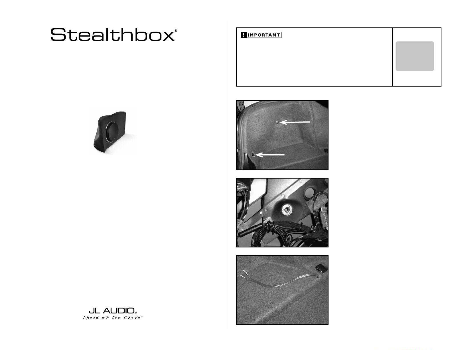
STEP 1
Remove all contents from the trunk.
Side Clip
Remove the two plastic clips from the driver’s side of the
trunk, that are indicated by the arrows in the picture.
Remove this side panel from the trunk.
STEP 2
Place the supplied weld nut into the same mounting hole as
the side position factory clip that was removed
in STEP 1.
Mark the three holes from the flange of the weld nut onto
the factory metal pane. Remove the weld nut.
With a 1/8-inch drill bit and drill. Drill out the metal panel at
the marked locations. You are close the outside sheet metal,
use care when drilling through the metal.
Secure the threaded insert with the three supplied rivets.
STEP 3
Run speaker wire from the amplifier location to the
Stealthbox® location.
INSTALLATION
DIFFICULTY:
OUT
OF
5
ESTIMATED TIME:
1 HOUR
Continued on Next Page
Page 2
SB-B-5SER/12W6v2_INSTR_SKU#011233
SB-B-5SER/12W6v2_INSTR_SKU#011233
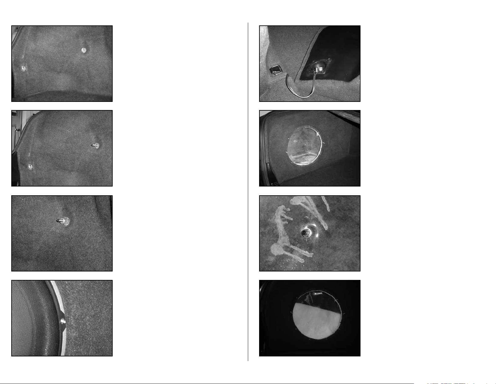
STEP 4
Place the side panel back into the trunk.
STEP 5
Place the rear factory clip back into place.
Thread the supplied set screw stud into the weld nut,
leave 1 1/2-inch exposed.
STEP 6
Place the supplied spacer onto the set screw stud.
STEP 8
Attach the speaker wire to the terminal on the Stealthbox®.
STEP 9
Position the Stealthbox into position.
Carefully guide the threaded stud through the hole on the
back side of the Stealthbox®.
STEP 10
From inside the Stealthbox®, place the supplied washer, lock
wash and then nut onto the set screw stud.
Page 2 • JL Audio, Inc 2007
STEP 7
Remove the 9 o’clock and 3 o’clock position mounting
screws from the woofer. Replace these mounting screws
with the supplied threaded rods.
Remove all the mounting screws, woofer and fill from the
Stealthbox®.
Using a 9/16-inch deep socket, secure tightly.
Do not over tighten.
STEP 11
Place the fill back into the Stealthbox®.
Continued on Next Page
Page 3

SB-B-5SER/12W6v2_INSTR_SKU#011233
SB-B-5SER/12W6v2_INSTR_SKU#011233
JLA-SKU#011233 -05-01-200
(1)
7/8-inch(L) x 3/4-inch(OD) x 3/8-inch(ID) Spacer
(1)
3/8-inch -16 x 3” Set Screw Stud
(1)
3/8-inch -16 x 5/8-inch Weld Nut
(1)
3/8-inch -16 Hex Nut
(1)
3/8-inch Spilt Lock Washer
(3)
Button Head Rivet
(1)
3/8-inch Flat Washer
Acoustic Suspension (sealed)
12W6v2-D4
2 ohms mono
400 Watts
P O W E R R E C O M M E N D A T I O N
4.0-inch / Front Doors
TR400-CXi
4.0-inch / Rear Door
TR400-CXi
STEP 20
Attach the proper speaker wires to the woofer’s terminal.
STEP 21
Using the threaded rods as guide, place the woofer back
onto the Stealthbox® and mount.
STEP 22
Remove the two threaded rods, a pair of pliers help with this
removal.
INCLUDED HARDWARE
(1)
7/8-inch(L) x 3/4-inch(OD) x 3/8-inch(ID) Spacer
(1)
3/8-inch -16 x 5/8-inch Weld Nut
(1)
3/8-inch Spilt Lock Washer
(1)
3/8-inch Flat Washer
(1)
3/8-inch -16 x 3” Set Screw Stud
(1)
3/8-inch -16 Hex Nut
(3)
Button Head Rivet
SPECIFICATIONS
Enclosure Type:
Driver Type:
Nominal Impedance:
Continuous Power Handling:
POWER RECOMMENDATION
Acoustic Suspension (sealed)
12W 6v2 -D 4
2 ohms mono
400 Watts
JL Audio recommends using a high quality amplifier such as the JL Audio 500/1v2.
The diagram below shows the recommended crossover, infrasonic filter and equalizer settings for the 500/1v2
when being used to power your Stealthbox®.
Signal Sensing
Off / On
Subwoofer Output
_
+
+
MONO OUTPUT ONLY
_
+12VDC RemoteGround
JL AUDIO 500/1
five-channel system amplifier
Preamp Output Section
Output Mode
Full Range / Amp Filter / Out Filter
Left Ch. Right Ch.
Filter Slope
12dB / 24dB
556585
45
40
Filter Freq. (Hz)
Infrasonic Filter
"Q"
Center Freq.
1.6
1.1
2.7
354555
0.7
Off / 30Hz
Filter Mode
253040
18
120
15
200
LP / HP
Infrasonic Freq. (Hz)
25
0.5
4.3
20
85
Bass EQ
50
60
Off / On
Remote Bass Port
Amp LP Filter
Boost (dB)
+10
+4
+13
70
0
+15
Advanced
Bass
Control
Mode / Slope
Off / 12dB / 24dB
556585
45
40
Filter Freq. (Hz)
120
200
Amplifier Input Section
Input Sens.
Input Voltage
Low / High
Left Ch.
Right Ch.
The JL Audio 250/1 is a very versatile audio component. Please consult the owner’s manual for even more
detailed information about installing and tuning this amplifier.
Page 3 • JL Audio, Inc 2007
Finish securing the woofer with the last two mounting
screws.
CONGRATULATIONS
You have completed the installation for this model!
Please refer to the Power Recommendation section for an
amplifier recommendation and basic set-up help.
MID/HIGH FREQUENCY DRIVER FITMENT
A variety of JL Audio coaxial and component systems will fit in the factory speaker locations of you vehicle.
Front Speaker Size / Location:
Fits JL Audio Models:
Rear Speaker Size / Location:
Fits JL Audio Models:
All specifications are subject to change without notice. “JL Audio®” and the JL Audio logo, “Stealthbox” and the Stealthbox logo are registered
trademarks of JL Audio, Inc. “Ahead of the Cur ve” and its respective logo is a trademark of JL Audio, Inc.
JLA-SKU#011233 -05-01-20077 • Printed in USA • ©2007 JL Audio, Inc. • U.S. PATENTS: #5,734,734 #5,949,898 #6,118,884 #6,229,902
#6,243,479 #6,294,959 #6,501,844 #6,496,590 #6,441,685 #5,687,247 #6,219,431 #6,625,292 #D472,891 #D480,709 Other U.S. & Foreign
patents pending. For more detailed information please visit us online at www.jlaudio.com.
10369 NORTH COMMERCE PARKWAY • MIRAMAR, FLORIDA • 33025 • USA
4.0-inch / Front Doors
TR400-CXi
4.0-inch / Rear Door
TR400-CXi
(954) 443-1100
www.jlaudio.com
 Loading...