

JL Audio NexD XD700/5 Owner's Manual
Thank you for purchasing a JL Audio amplifier for
your automotive sound system.
Your amplifier has been designed and manufactured to exacting
standards in order to ensure years of musical enjoyment in your vehicle.
For maximum performance, we highly recommend that you have
your new amplifier installed by an authorized JL Audio dealer. Your
authorized dealer has the training, expertise and installation equipment
to ensure optimum performance from this product. Should you
decide to install the amplifier yourself, please take the time
to read this manual thoroughly so as to familiarize yourself
with its installation requirements and setup procedures.
If you have any questions regarding the instructions in this
manual or any aspect of your amplifier’s operation, please contact your
authorized JL Audio dealer for assistance. If you need further assistance,
please call the JL Audio Technical Support Department
at (954) 443-1100 during business hours.
OWNER’S MANUAL
700W 5-Channel Amplier with 2-Way / 3-Way Crossover

2 | JL Audio - XD700/5 Owner’s Manual
PROTECT YOUR HEARING!
We value you as a long-term customer. For
that reason, we urge you to practice restraint in
the operation of this product so as not to damage
your hearing and that of others in your vehicle.
Studies have shown that continuous exposure to
high sound pressure levels can lead to permanent
(irreparable) hearing loss. This and all other
high-power amplifiers are capable of producing
such high sound pressure levels when connected
to a speaker system. Please limit your continuous
exposure to high volume levels.
While driving, operate your audio system in
a manner that still allows you to hear necessary
noises to operate your vehicle safely (horns,
sirens, etc.).
SERIAL NUMBER
In the event that your amplifier requires
service or is ever stolen, you will need to have
a record of the product’s serial number. Please
take the time to enter that number in the space
provided below. The serial number can be found
on the bottom panel of the amplifier and on the
amplifier packaging.
Serial Number:
INSTALLATION APPLICATIONS
This amplifier is designed for operation in
vehicles with 12 volt, negative-ground electrical
systems. Use of this product in vehicles with
positive ground and/or voltages other than 12V
may result in damage to the product and will void
the warrant y.
This product is not certified or approved for
use in aircraft.
Do not attempt to “bridge” the outputs of this
amplifier with the outputs of a second amplifier,
including an identical one.
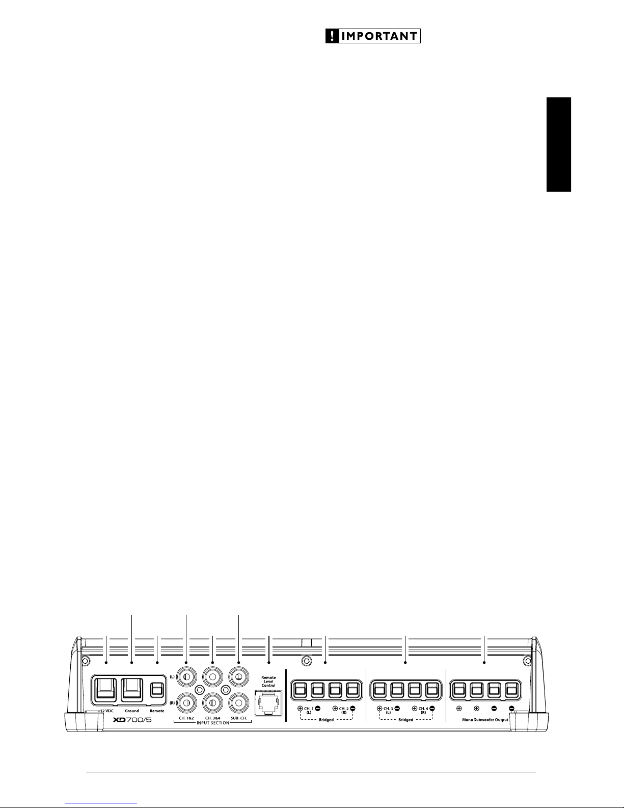
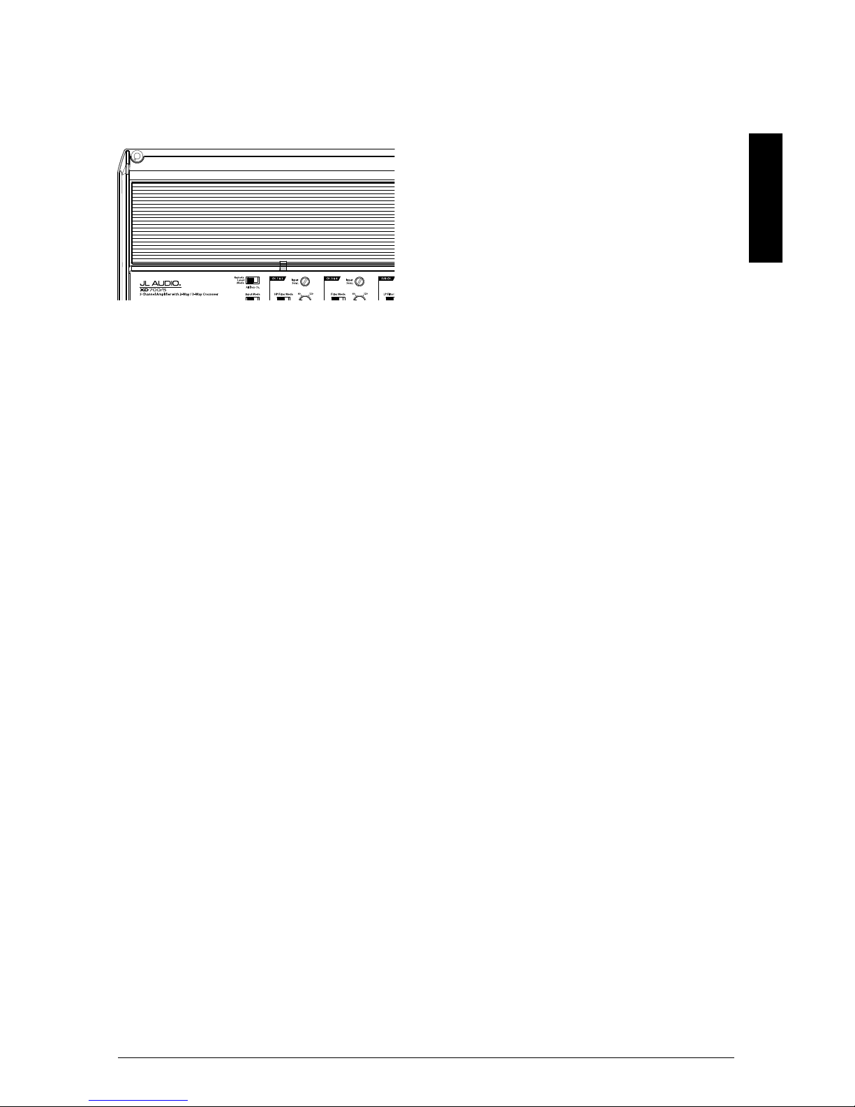
Status
LED
(pg. 11)
Ch. 1 & 2 Filter
Frequency
Selector
(pg. 8)
Ch. 1 & 2
Filter Mode
Selection
(pg. 8)
Ch. 1 & 2 Input
Sensitivity Control
(pg. 7)
Remote
Level Mode
Switch
(pg. 9)
Input
Mode
Switch
(pg. 7)
Ch. 3 & 4 Filter
Frequency
Selector
(pg. 8)
Ch. 3 & 4
Filter Mode
Selection
(pg. 8)
Ch. 3 & 4 Input
Sensitivity Control
(pg. 7)
Sub. Ch. Filter
Frequency
Selector
(pg. 8)
Sub. Ch.
Filter Mode
Selection
(pg. 8)
Sub. Ch. Input
Sensitivity Control
(pg. 7)
3
ENGLISH
PLANNING YOUR INSTALLATION
It is important that you take the time to read
this manual and that you plan out your
installation carefully. The following are some
considerations that you must take into account
when planning your installation.
Cooling Efficiency Considerations:
The outer shell of your JL Audio amplifier is
designed to remove heat from the amplifier
circuitry. For optimum cooling performance, this
outer shell should be exposed to as large a volume
of air as possible. Enclosing the amplifier in a
small, poorly ventilated chamber can lead to
excessive heat build-up and degraded
performance. If an installation calls for an
enclosure around the amplifier, we recommend
that this enclosure be ventilated with the aid
of a fan. In normal applications, fan-cooling
is not necessary.
Mounting the amplifier upside down is
strongly discouraged. If mounting the amplifier
under a seat, make sure there is at least 1 inch
(2.5 cm) of space above the amplifier’s outer
shell to permit proper cooling.
Safety Considerations:
Your amplifier needs to be installed in a dry,
well-ventilated environment and in a manner
which does not interfere with your vehicle’s safety
equipment (air bags, seat belt systems, ABS brake
systems, etc.). You should also take the time to
securely mount the amplifier so that it does not
come loose in the event of a collision or a sudden
jolt to the vehicle.
Stupid Mistakes to Avoid
• Check before drilling any holes in your vehicle
to make sure that you will not be drilling
through a gas tank, brake line, wiring harness or
other vital vehicle system.
• Do not run system wiring outside or underneath
the vehicle. This is an extremely dangerous
practice which can result in severe damage to
your vehicle and person.
• Protect all system wires from sharp metal
edges and wear by carefully routing them,
tying them down and using grommets and
loom where appropriate.
• Do not mount the amplifier in the engine
compartment, under the vehicle, on the roof
or in any other area that will expose the
amplifier circuitry to the elements.
Remote Turn-On
Connector
(pg. 6)
Chassis Ground
Connector
(pg. 5)
Channels 1 & 2
Preamp Input Jacks
(pg. 7)
Subwoofer Ch.
Preamp Input Jacks
(pg. 7)
+12 V Power
Connector
(pg. 5)
Mono
Subwoofer Outputs
(pg. 10)
Channels 3 & 4
Speaker Outputs
(pg. 10)
Channels 1 & 2
Speaker Outputs
(pg. 10)
Jack for
Remote Level
Control Knob
(pg. 9)
Channels 3 & 4
Preamp Input Jacks
(pg. 7)

4 | JL Audio - XD700/5 Owner’s Manual
PRODUCT DESCRIPTION
The JL Audio XD700/5 is a five-channel,
system amplifier utilizing JL Audio NexD™ ultrahigh speed switching technology for its four main
channels and NexD™ high-speed switching for
its subwoofer channel. The NexD™ technologies
deliver outstanding fidelity and efficiency.
The XD700/5 can be operated with a wide
variety of source units and system configurations.
TYPICAL INSTALLATION SEQUENCE
The following represents the sequence
for a typical amplifier installation, using an
aftermarket source unit or OEM Interface
processor (like the CleanSweep CL441dsp).
Additional steps and different procedures may
be required in some applications. If you have
any questions, please contact your authorized
JL Audio dealer for assistance.
1) Disconnect the negative battery post
connection and secure the disconnected cable
to prevent accidental re-connection during
installation. This step is not optional.
2) Run 4 AWG power wire from the battery
location to the amplifier mounting location.
Take care to route the wire in such a way that
it will not be damaged and will not interfere
with vehicle operation. Use 2 AWG or larger
power wire and a power distribution block if
additional amplifiers are being installed with
the XD700/5.
3) Connect power wire to the positive battery
post. Fuse the wire with an appropriate fuse
block (and connectors) within 18 inches (45
cm) wire length of the positive battery post.
This fuse is essential to protect the vehicle.
Do not install the fuse until the power wire
has been securely connected to the amplifier.
4) Run signal cables and remote turn-on wire
from the source unit to the final amplifier
mounting location.
5) Run speaker cables from the speaker systems
to the amplifier mounting location.
6) Find a good, solid metal grounding point
close to the amplifier and connect the
negative power wire to it using appropriate
hardware (use of the JL Audio ECS master
ground lug, XB-MGLU is recommended).
Use 4 AWG wire, no longer than 36 inches
(90 cm) from the amplifier to the ground
connection point. In some vehicles, it may
be necessary to upgrade the battery ground
wire. (See page 5 for important notice).
7) Securely mount the amplifier.
8) Connect the positive and negative power
wires to the amplifier. A fuse near
the amplifier is not necessary if the
XD700/5 is the only device being run
from the fused main power wire. If
the fused main power wire is shared
by the XD700/5 and other amplifiers
or devices, fuse each amplifier/device
within 12 inches (30 cm) of wire length,
via a fused distribution block or multiple
individual fuse blocks/on-board fuses.
9) Connect the remote turn-on wire
to the amplifier.
10) Connect the input cables to the amplifier.
11) Connect the speaker cables to the amplifier.
12) Carefully review the amplifier’s control
settings to make sure that they are set
according to the needs of the system.
13) Install the power wire fuse(s) (60A for a
single XD700/5) and reconnect the negative
battery post terminal.
14) Turn on the source unit at a low level
to double-check that the amplifier is
configured correctly. Resist the temptation
to crank it up until you have verified the
control settings.
15) Make necessary adjustments to the input
sensitivity controls to obtain the right
overall output and the desired balance
in the system. See Appendix A (page 14)
for the recommended input sensitivity
setting method.
16) Enjoy the fruits of your labor with your
favorite music.
5
ENGLISH
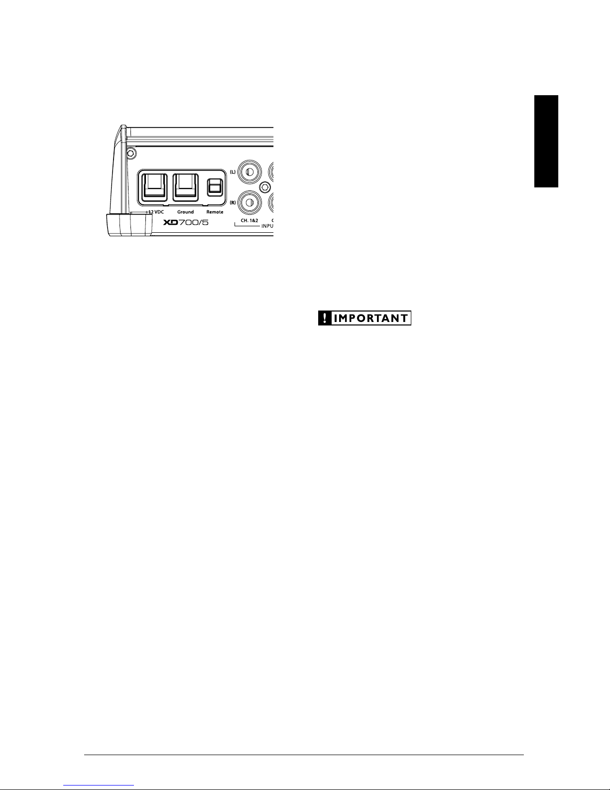
POWER CONNECTIONS
Before installing the amplifier, disconnect the
negative (ground) wire from the vehicle’s battery.
This will prevent accidental damage to the system,
the vehicle and your body during installation.
The XD700/5’s “+12 VDC” and “Ground”
connections are designed to accept 4 AWG
power wire. 4 AWG is the required wire size for
this amplifier.
If you are installing the XD700/5 with other
amplifiers and wish to use a single main power
wire, use 2 AWG or 1/0 AWG main power wire
(depending on the overall current demands of all
the amplifiers in the system). This large power
wire should terminate into a fused distribution
block mounted as close to the amplifiers as
possible (within 12 inches / 30cm of wire length).
The fused output of the distribution block will
connect to the XD700/5 with 4 AWG power
wire. JL Audio ECS fused distribution blocks are
recommended (XD-FDBU-2 and XD-FDBU-4)
Note: Smaller AWG numbers mean bigger
wire and vice-versa (1/0 AWG is the largest, 2
AWG is smaller, then 4 AWG, then 8 AWG, etc.).
To connect the power wires to the amplifier,
first back out the set screw on the top of the
terminal block, using the supplied 2.5 mm hex
wrench. Strip 1/2 inch (12 mm) of insulation from
the end of each wire and insert the bare wire into
the terminal block, seating it firmly so that no
bare wire is exposed. While holding the wire in
place, tighten the set screw firmly, taking care not
to strip the head of the screw.
The ground connection should be made
using 4 AWG wire and should be kept as
short as possible, while accessing a solid
piece of sheet metal in the vehicle. The
surface of the sheet metal should be sanded
at the contact point to create a clean, metalto-metal connection between the chassis
and the termination of the ground wire.
For optimal grounding, we recommend the
use of a JL Audio ECS master ground lug
(XB-MGLU). Alternatively, a sheet metal
screw or bolt can be used with a star washer.
Any wires run through metal barriers (such
as firewalls), must be protected with a high
quality rubber grommet to prevent damage to the
insulation of the wire. Failure to do so may result
in a dangerous short circuit.
Many vehicles employ small (10 AWG -
6 AWG) wire to ground the battery to the
vehicle chassis and to connect the alternator's
positive connection to the battery. To prevent
voltage drops, these wires should be upgraded
to 4 AWG when installing amplifier systems
with main fuse ratings above 60A.
FUSE REQUIREMENTS
It is absolutely vital that the main power
wire(s) to the amplifier(s) in the system be
fused within 18 inches (45 cm) of the positive
battery post connection. The fuse value at each
power wire should be high enough for all of the
equipment being run from that power wire. If
only the XD700/5 is being run from that power
wire, we recommend a 60A fuse be used.
If fusing the amplifier near its power
connections (when more than one amp is being
run from the main power wire), use a 60A fuse.
MAXI™ plastic-body fuses are recommended.

6 | JL Audio - XD700/5 Owner’s Manual
TURNON LEAD
The XD700/5 uses a conventional +12V remote
turn-on lead, typically controlled by the source
unit's remote turn-on output. The amplifier will
turn on when +12V is present at its “Remote”
input and turn off when +12V is switched off. If
a source unit does not have a dedicated remote
turn-on output, the amplifier’s turn-on lead can
be connected to +12V via a switch that derives
power from an ignition-switched circuit.
The XD700/5’s “Remote” turn-on connector
is designed to accept 18 AWG – 12 AWG wire. To
connect the remote turn-on wire to the amplifier,
first back out the set screw on the top of the
terminal block, using the supplied 2.5mm hex
wrench. Strip 1/2 inch (12mm) of wire and insert
the bare wire into the terminal block, seating it
firmly so that no bare wire is exposed. While
holding the wire in the terminal, tighten the set
screw firmly, taking care not to strip the head of
the screw and making sure that the wire (not the
insulation) is firmly gripped by the wire clamp in
the terminal.
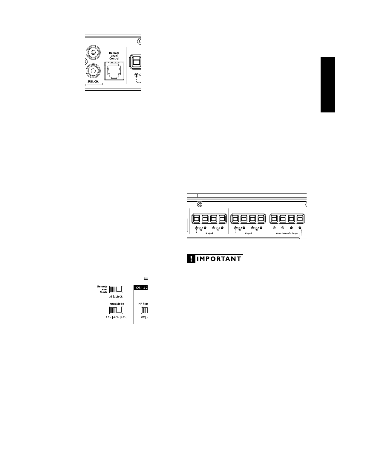
INPUT SECTION
The XD700/5’s input section allows you to send
signals to the amplifier section through the use
of two, four or six differential-balanced inputs.
Input connections are via up to three pairs of
traditional RCA-type jacks.
If you wish to send six discrete channels into
the XD700/5, simply use all six inputs and set the
“Input Mode” switch in the “6 Ch.” position. The
amplifier will automatically combine the Sub Ch.
input signals to mono.
If you prefer to use only four channels of input
into the XD700/5, set the “Input Mode” switch
in the “4 Ch.” position and use the Ch 1 & 2 and
Ch 3 & 4 Inputs. In this mode, the XD700/5 will
derive its subwoofer channel signal from a sum
of all four input signals. The bass will not fade
when the signal is faded by the head unit from
front to rear.
You may also choose to apply only two
channels of input to deliver signal to all five
amplifier channels. To do this, set the “Input
Mode” switch to “2 Ch.” and use only the inputs
to channels 1 & 2. In this mode, Channel 3 will
operate with the Channel 1 signal and Channel
4 will operate with the Channel 2 signal. The
amplifier will automatically combine the main
input signals to mono for the Subwoofer Channel.
7
ENGLISH
Input Voltage Range:
The XD700/5’s input sections are designed to
accept signal voltages from 100mV – 4V. This
will accommodate all preamp level signals and
many speaker level signals.
To use speaker-level sources, simply splice the
speaker output wires of the source unit onto a
pair of RCA plugs for each input pair. (or use
JL Audio part XD-CLRAIC2-SW) No “line
output converter” is needed in most cases.
If you find that the output cannot be reduced
sufficiently with a direct speaker level signal
applied to the amplifier, you may use a “line
output converter” to reduce the signal level.
INPUT SENSITIVITY CONTROLS
The controls labeled “Input Sens.” located in
each channel section can be used to match the
source unit’s output voltage to the input stage of
each pair of amplifier channels for maximum
clean output. Rotating the control clockwise will
result in higher sensitivity (louder for a given
input voltage). Rotating the control counterclockwise will result in lower sensitivity (quieter
for a given input voltage.)
To properly set the amplifier for maximum
clean output, please refer to Appendix A (page
14) in this manual. After using this procedure,
you can then adjust any or all “Input Sens.”
levels downward if this is required to achieve the
desired system balance.
Do not increase any “Input Sens.” setting for
any channel(s) of any amplifier in the system
beyond the maximum level established during
the procedure outlined in Appendix A (page 14).
Doing so will result in audible distortion and
possible speaker damage.
FILTER CONTROLS
Most speakers are not designed to reproduce
the full range of frequencies audible by the human
ear. For this reason, most speaker systems are
comprised of multiple speakers, each dedicated
to reproducing a specific frequency range. Filters
are used to select which frequency range is sent to
each section of a speaker system. The division of
frequency ranges to different speakers can be done
with passive filters (coils and/or capacitors between
the amplifier outputs and the speakers), which
are acceptable and commonly used for filtering
between mid-range speakers and tweeters. Filtering
between subwoofer systems and satellite speaker
systems is best done with active filters, which cut
off frequency content at the input to the amplifier.
Active filters are more stable than passive filters
and do not introduce extraneous resistance, which
can degrade subwoofer performance.
The active filter built into each channel section
of the XD700/5 can be used to eliminate
potentially harmful and/or undesired frequencies
from making their way through the amplifier
sections to the speaker(s). This serves to improve
tonal balance and to avoid distortion and possible
speaker failure. Correct use of these filters can
substantially increase the longevity and fidelity of
your audio system.
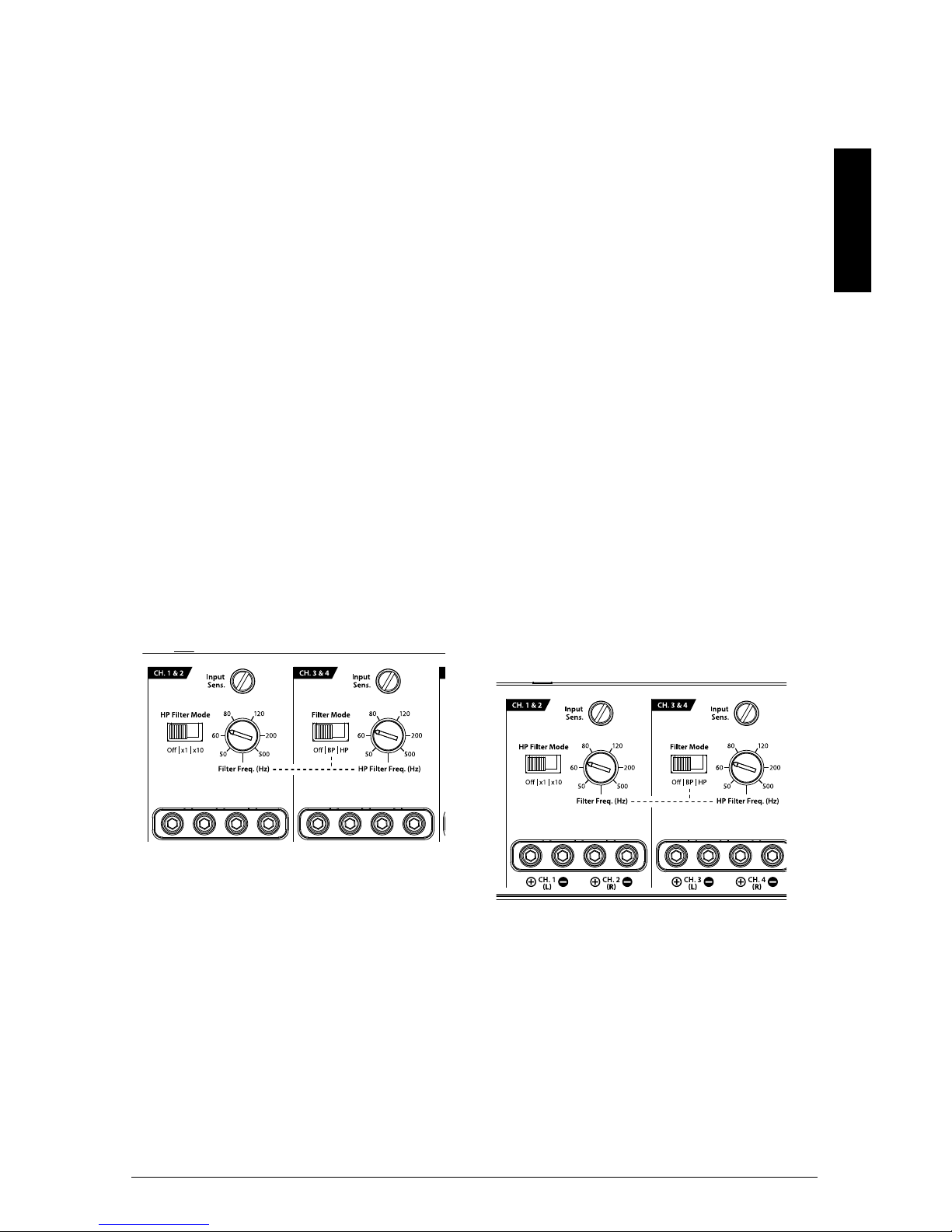
1) “Filter Mode” Controls: The XD700/5
employs 12dB per octave filters for each pair
of main channels (one high-pass filter for
channels 1&2 and another high-pass / bandpass
filter for channels 3&4. The Subwoofer Channel
provides a low-pass filter with the option of
12dB or 24dB / octave slopes. Each of these
filters can be controlled or defeated completely
by way of the three-position “Filter Mode”
switches in each Channel Section:

8 | JL Audio - XD700/5 Owner’s Manual
Channel 1 & 2 Filter: 12dB/octave High-Pass
only, with x10 multiplier switch
“Off ”: Defeats the filter completely, allowing
the full range of frequencies present at the inputs
to feed these channels. This is useful for systems
utilizing outboard active crossovers or requiring
full-range reproduction this channel pair.
“x1” (High-Pass): Configures the filter
to attenuate frequencies below the indicated
filter frequency at a rate of 12dB per octave.
This is useful for connection of component
speakers or coaxials to this channel pair in a
bi-amplified system.
“x10” (High-Pass): Configures the filter to
attenuate frequencies below a frequency TEN
TIMES HIGHER than the indicated filter
frequency at a rate of 12dB per octave. This is
useful for connection of tweeters to this channel
pair in a tri-amplified system.
Channel 3 & 4 Filter: 12dB/octave High-Pass
or Bandpass Filter
“Off ”: Defeats the filter completely, allowing
the full range of frequencies present at the inputs
to feed these channels. This is useful for systems
utilizing outboard active crossovers or requiring
full-range reproduction this channel pair.
“BP” (High-Pass): Configures the filter to
attenuate frequencies below the indicated filter
frequency AND above the Channel 1 & 2 Filter
Frequency, at a rate of 12dB per octave. This is
useful for connection of mid-bass or mid-range
speakers in a tri-amplified system.
“HP” (High-Pass): Configures the filter
to attenuate frequencies below the indicated
filter frequency at a rate of 12dB per octave.
This is useful for connection of component
speakers or coaxials to this channel pair in a
bi-amplified system.
Subwoofer Channel Filter: 12dB/octave
or 24dB / octave, Low-Pass only
“Off ”: Defeats the filter completely, allowing
the full range of frequencies present at the inputs
to feed this channel. This is useful for systems
utilizing outboard active crossovers.
“12dB” (Low-Pass): Configures the filter
to attenuate frequencies above the indicated
filter frequency at a rate of 12dB per octave.
This is useful for connection of subwoofers in a
bi-amplified system. This shallower slope gently
attenuates high-frequencies from your subwoofer
signal and is often well-suited for sedans and
coupes with trunks.
“24dB” (Low-Pass): Configures the filter
to attenuate frequencies above the indicated
filter frequency at a rate of 24dB per octave.
This is useful for connection of subwoofers in
a bi-amplified system. This sharper slope more
aggressively removes high-frequencies from your
subwoofer signal and is often well-suited for
SUV’s, wagons and hatchbacks.
2) “Filter Freq. (Hz)” The filter frequency
markings surrounding these rotary controls
(one in each Channel Section) are for reference
purposes and are generally accurate to within
1/3 octave or better. If you would like to select
the filter cutoff frequency with a higher level
of precision, consult the chart in Appendix B
(page 15).
Tuning Hint: If you are using the XD700/5
to drive a subwoofer system (“LP” mode), and
component satellite speaker systems (“HP” mode),
80 Hz is a good baseline “Filter Freq. (Hz)” setting.
After properly adjusting the “Input Sens.”, as
outlined in Appendix A (page 14), you can fine
tune the “Filter Freq. (Hz)” control to achieve the
desired system frequency response.
9
ENGLISH
REMOTE LEVEL CONTROL OPTIONAL
With the addition of the optional Remote
Level Control (HD-RLC), you can control the
volume of the subwoofer channel (Subwoofer
Level) or of the entire XD700/5 from the front of
the vehicle (Master Volume).
The HD-RLC connects to the jack labeled
“Remote Level Control” on the Connection Panel
of the amplifier using a standard telephone cable
(supplied with the HD-RLC). If desired, multiple
XD (and HD) amplifiers can be controlled from
a single HD-RLC controller using a simple phone
line “splitter” and multiple phone cables.
When connected to the amplifier, the
HD-RLC operates as follows. At full counterclockwise rotation, the audio of the selected
channels will mute completely. At full clockwise
rotation the level will be the same as if the
HD-RLC was not connected at all. In other
words, it operates strictly as a level attenuator.
“Remote Level Mode” Switch: This switch
allows you to assign the operation of the
HD-RLC to the entire amplifier or only the
subwoofer channel. In the “Al l” position, the
HD-RLC knob will affect all channels equally.
In the “Sub Ch.” position, only the level of
the subwoofer channel will be affected by the
HD-RLC knob.
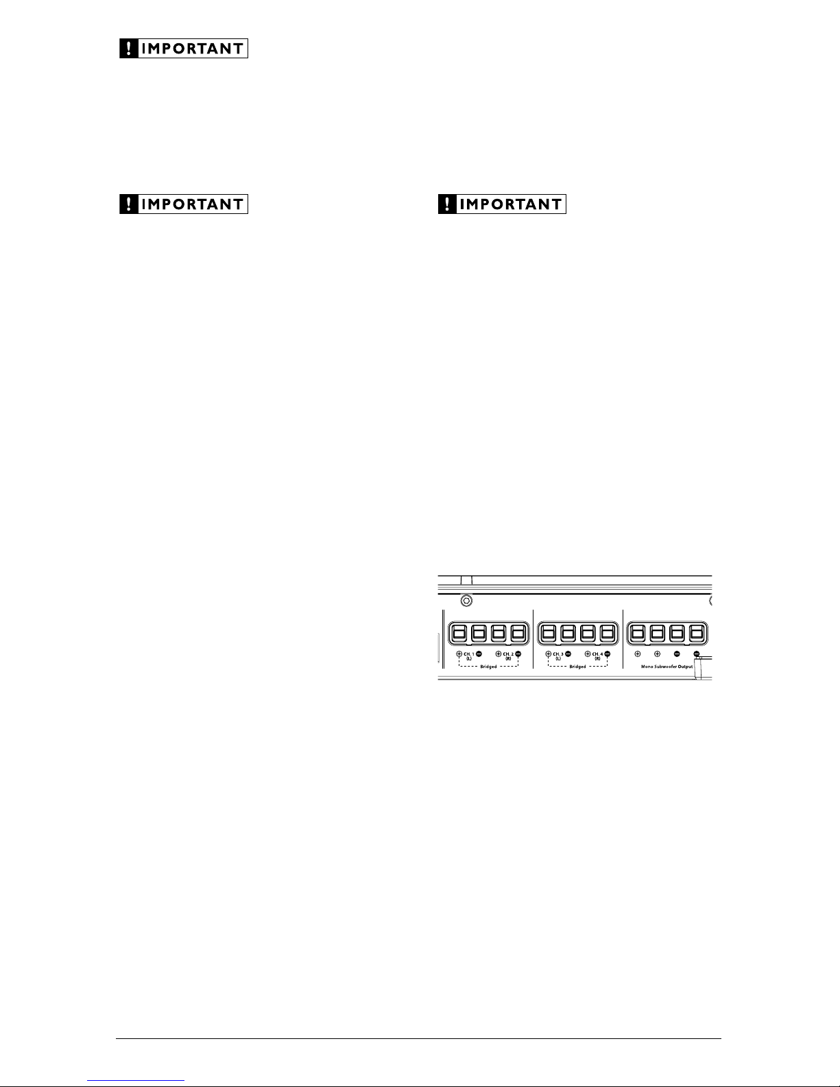
SPEAKER OUTPUTS
The XD700/5’s speaker outputs are designed
to accept 16 AWG - 8 AWG wire. To connect the
speaker wires to the amplifier, first back out the
set screws on the top of the terminal block, using
the supplied 2.5 mm hex wrench. Strip 1/2 inch
(12 mm) of insulation from the end of each wire
and insert the bare wire into the terminal block,
seating it firmly so that no bare wire is exposed.
While holding the wire in place, tighten the set
screw firmly, taking care not to strip the head of
the screw.
Each pair of the XD700/5’s main channels are
designed to deliver power into speaker loads equal
to or greater than 2 ohms when using a “stereo”
configuration and speaker loads equal to or greater
than 4 ohms when using a “bridged” configuration.
The subwoofer channel is designed to deliver power
into subwoofer loads equal to or greater than 2 ohms.
Speaker loads below 2 ohms nominal per
channel (or 4 ohms bridged) are not
recommended and may cause the amplifier
to initiate a protection mode which reduces
power output.
BRIDGING CONSIDERATIONS
Bridging is the practice of combining the
output of two amplifier channels to drive a single
load. When bridged, each channel produces
signals of equal magnitude, but opposite polarity.
The combined output of the two channels
provides twice the output voltage available from
a single channel. The XD700/5 has been designed
for bridging of its main channel pairs without the
need for input inversion adaptors.
To bridge a pair of main channels, use the
“Left +” and “Right –” speaker connectors only
(the “Left –” and “Right +” remain unused). Each
bridged channel pair will deliver optimum power
into a 4 ohm load.
10 | JL Audio - XD700/5 Owner’s Manual
When a pair of the XD700/5’s main channels
are bridged, they will deliver 200W x 1 into a
4 ohm load or 150W x 1 into an 8 ohm load.
Operating a pair of bridged channels into a
load lower than 4 ohms is not recommended.
A bridged pair of channels requires that both
channels in the pair receive input. You must
connect the mono or stereo source signal to
both the left and right inputs the bridged
channel pair. Connection of only one input will
result in reduced power output, increased
distortion and can cause the amplifier to
overheat. Do not do this!
When a pair of the XD700/5’s main channels
are operating in bridged mode, the output will be
in mono (only one channel). This mono channel
can contain only right channel information, only
left channel information, or the sum of the signals
from right and left input channels. In order to
achieve one of these options, configure the inputs
to that pair of channels in one of these two ways:
1) Left Channel Only or Right Channel Only
Information: If you wish to send a left-only
or right-only signal to a pair of the XD700/5’s
channels you must use a “Y-Adaptor” to split
the single channel signal into both left and
right RCA inputs of the bridged channel
pair. This option is used when deploying a
pair of the XD700/5’s main channels to drive
left channel speakers only and the other pair
of the XD700/5’s main channels to drive right
channel speakers only.
2) Left + Right Channel Information: When
bridged and fed by a stereo source signal, a
bridged pair of the XD700/5’s channels will
automatically combine the left and right input
signals into a summed mono (left + right)
input signal.
SUBWOOFER OUTPUTS
The XD700/5’s single subwoofer channel is
designed to deliver power into subwoofer loads
equal to or greater than 2 ohms. It is rated for
300W into 2 ohms, 250W into 3 ohms and 200W
into 4 ohms (Continuous Power, RMS Method).
Subwoofer loads below 2 ohms nominal are not
recommended and may cause the amplifier
to initiate a protection mode which reduces
power output.
The XD700/5’s subwoofer outputs are
designed to accept 16 AWG - 8 AWG wire. To
connect the subwoofer wires to the amplifier,
first back out the set screws on the top of the
terminal block, using the supplied 2.5 mm hex
wrench. Strip 1/2 inch (12 mm) of insulation
from the end of each wire and insert the bare
wire into the terminal block, seating it firmly
so that no bare wire is exposed. While holding
the wire in place, tighten the set screw firmly,
taking care not to strip the head of the screw.
You will notice that there are two “+” positive
connections and two “–” negative connections.
This is to facilitate multiple subwoofer wiring.
The two positive and two negative connections
are connected in parallel inside the amplifier
They are not stereo outputs. Connecting two
subwoofers, each to one set of positive and
negative terminals, will result in a parallel
subwoofer connection. If only connecting one
pair of subwoofer wires, it is not necessary to use
both sets of connections.
11
ENGLISH
STATUS LED / PROTECTION CIRCUITRY
There is a single multi-color LED on the top
surface of the amplifier to indicate the amplifier’s
operating status.
1) Flashing Green: amplifier is powering up,
audio output is muted.
2) Constant Green: amplifier is on and
functioning normally, audio output is active.
3) Constant Red: Indicates that the amplifier has
exceeded its safe operating temperature, putting
the amplifier into a self-protection mode, which
reduces the peak power output of the amplifier.
When its temperature returns to a safe level, the
red light will return to green and the amplifier
will return to full-power operating mode.
4) Constant Amber (yellow): Indicates that
an over-current condition has occurred and
is accompanied by a muting of the affected
channel(s). Because the muting behavior may be
very short in duration, it may manifest itself as
an audible, repetitive ticking noise in the output.
Over-current conditions can be caused by a
speaker impedance lower than the optimum load
impedance range for the amplifier or a shortcircuit in the speaker wiring. The latter can result
from a short circuit between the positive and
negative speaker wires or between either speaker
wire and the vehicle chassis. The “Status LED”
will remain amber for a few seconds, even if the
over-current condition is of a very short duration.
This functionality can be used to diagnose a
short-circuit by only connecting one channel at
a time. The “Status LED” will turn amber when
you connect the channel that is experiencing the
problem and turn the volume up.
5) LED off / Amplifier Shuts Off Unexpectedly
The only condition that will shut down
an undamaged XD700/5 completely is if battery
voltage or remote turn-on voltage drops below
10 volts. The “Status LED” will turn off when
this occurs. The amplifier will turn back on
when voltage climbs back above 11 volts. If this
is happening in your system, have your charging
system and power wiring inspected.
For more information on troubleshooting this
amplifier, refer to Appendix D (pages 16, 17).
SERVICING YOUR JL AUDIO AMPLIFIER
If your amplifier fails or malfunctions, please
return it to your authorized JL Audio dealer so
that it may be sent in to JL Audio for service.
There are no user serviceable parts or fuses inside
the amplifier. The unique nature of the circuitry
in the JL Audio amplifiers requires specifically
trained service personnel. Do not attempt
to service the amplifier yourself or through
unauthorized repair facilities. This will not only
void the warranty, but may result in the creation of
more problems within the amplifier.
If you have any questions about the installation or
setup of the amplifier not covered in this manual,
please contact your dealer or technical support.
JL Audio Technical Support:
(954) 443-1100
9:00 AM – 5:30 PM (Eastern Time Zone)
Monday - Friday

12 | JL Audio - XD700/5 Owner’s Manual
SYSTEM CONFIGURATIONS
The XD700/5 is a very flexible amplifier, wellsuited for a multitude of system configurations. In
this section, the most likely configurations for a
system with a single XD700/5 are explained in detail.
Once you have selected your desired
configuration, you can use the amplifier panel
drawing on pages 18 & 19 to mark the required
switch positions for easy reference.
BIAMPLIFIED SYSTEMS
Bi-amplified systems are defined as systems
in which separate amplifier channels drive lowfrequency (LF) and high-frequency (HF) speakers
and are separately filtered to send appropriate
frequency ranges to each speaker system.
The most common application of
bi-amplification in mobile audio is to drive a
subwoofer system from one or more amplifiers or
channels and component speakers from separate
amplifiers or channels.
The XD700/5 can be configured to drive a
bi-amplified system by itself.
Bi-Amplified System with one XD700/5
In this configuration, the Subwoofer Channel
of the XD700/5 will drive a subwoofer system
with low-pass filtering. The Main Channels (1&2,
3&4) will drive component speakers in stereo
with high-pass filtering.
Crossover Setup for Bi-Amplified System
with one XD700/5:
Once the input sections have been configured
appropriately (see page 6), go to the “SUB CH.”
control section and select “12dB” or “24dB”
(low-pass) on the “LP Filter Mode” switch and
an appropriate “Filter Freq.” (80 Hz is a good
starting point). The “12dB” setting engages a
shallow filter slope that gradually attenuates
frequencies above the selected “Filter Freq.”
setting. The “24dB” setting engages a sharper
filter slope that more aggressively attenuates
frequencies above the selected “Filter Freq.”
setting. Neither setting is “better”, but in general,
the shallower “12dB” setting is more desirable for
a subwoofer having to fire from a trunk into the
cabin of a sedan or coupe. The sharper “24dB”
setting is typically better in a hatchback, SUV or
wagon application. Experiment to find the slope
setting that results in the smoothest subwoofer to
midbass transition.
Next, turn your attention to the “CH 1 & 2”
Controls and select “x1” (high-pass) on the “HP
Filter Mode” switch and select an appropriate
“Filter Freq.” (again, 80 Hz is a good starting
point). The “x1” setting means that the Filter
Freq. indicated on the dial is exactly what you are
selecting. (In the “x10” mode, the actual Filter
Frequency is ten times higher than the indicated
value. This setting is generally not used in
bi-amplified systems.)
Finally, turn your attention to the “CH 3 & 4”
Controls and select “HP” (high-pass) on the “Filter
Mode” switch and select an appropriate “Filter
Freq.” (again, 80 Hz is a good starting point).
Tri-Amplified Systems with one XD700/5
The XD700/5’s 3-way crossover capability
allows you to create true, tri-amplified systems by
selecting the appropriate settings described below.
In a tri-amplified configuration, the
Subwoofer Channel of the XD700/5 will drive
a subwoofer system, in mono, with low-pass
filtering. Channels 3 & 4 will drive component
woofers (or mid-range speakers) in stereo
with bandpass filtering (both a high-pass
and a low-pass filter applied). Channels 1 & 2
will drive high-frequency speakers (tweeters,
typically), in stereo, with high-pass filtering.
To operate a single XD700/5 in Tri-Amplified
mode, set the “Input Mode” switch in “2 Ch.”
mode, and apply a single set of stereo inputs to the
Ch. 1 & 2 Inputs only!
Crossover Setup for Tri-Amplified System
with one XD700/5:
First go to the “SUB CH.” control section
and select “12dB” or “24dB” (low-pass) on the
“LP Filter Mode” switch and an appropriate
“Filter Freq.” (80 Hz is a good starting point). The
“12dB” setting engages a shallow filter slope that
gradually attenuates frequencies above the selected
“Filter Freq.” setting. The “24dB” setting engages
 Loading...