

JL Audio NexD M600/6 Owner's Manual

Thank you for purchasing a JL Audio amplifier for
your marine sound system.
Your amplifier has been designed and manufactured to exacting
standards in order to ensure years of musical enjoyment in your vessel.
For maximum performance, we highly recommend that you have
your new amplifier installed by an authorized JL Audio dealer. Your
authorized dealer has the training, expertise and installation equipment
to ensure optimum performance from this product. Should you
decide to install the amplifier yourself, please take the time
to read this manual thoroughly so as to familiarize yourself
with its installation requirements and setup procedures.
If you have any questions regarding the instructions in this
manual or any aspect of your amplifier’s operation, please contact your
authorized JL Audio dealer for assistance. If you need further assistance,
please call the JL Audio Technical Support Department
at (954) 443-1100 during business hours.
OWNER’S MANUAL
600W Marine 3/4/5/6 Channel Amplier
2 | JL Audio - M600/6 Owner’s Manual
3
PLANNING YOUR INSTALLATION
It is important that you take the time to read
this m anual and t hat you plan out your
insta llation caref ully. The followi ng are some
considerat ions that you must t ake into account
when plan ning your ins tallation.
Cooling Efficiency Consid erations:
The outer shell of your JL Audio amplifier is
designed to remove heat from the amplifier
circuitry. For optimum cooling performance, this
outer shell should be exposed to as large a volume
of air as possible. Enclosing the amplifier in a
small, poorly ventilated chamber can lead to
excessive heat build-up and degraded
performance. If an installation calls for an
enclosure around the amplifier, we recommend
that t his enclosure be ventilated with the aid
of a fan. In normal applications, fan-cooling
is not nece ssary.
Mounting t he amplifier upsi de down is
strongly discouraged.
Safety Considerations:
Your amplifier needs to be installed in a dry,
well-ventilat ed environment a nd in a manner
which does not interfere with your vessel’s factory
installed electronic devices. You should also take
the time to securely mount the amplifier using the
supplied screws so that it does not come loose in
the event of a collision or a sudden jolt to the vessel.
Stupid Mistakes to Avoid:
• Check before drilling any holes in your vessel to
make sure that you will not be drilling through
the hull, a fuel tank, fuel line, wiring harness or
other v ital vessel sy stem.
• Do not run system wiring outside or underneath
the vessel. This is an extremely dangerous
practice which can result in severe damage to
your vess el and person.
• Protec t all system wires from sh arp edges
(metal, fiberglass, etc.) by carefully routing
them, tying them down and using grommets
and loom w here appropriate.
• Do not mount the amplifier in the engine
compartment or in any other area that will
expose the amplifier circuitry to the elements.
While this amplifier is specially designed
for marine applications, it is not waterproof
and it should not be mounted where it is
likely to get wet.
PROTECT YOUR H EARING!
We value you as a long-term customer. For
that rea son, we urge you to pr actice restra int in
the oper ation of this produc t so as not to d amage
your hearing and that of others in your vessel.
Studies have shown that cont inuous exposure to
high sound pressure levels can lead to permanent
(irrepara ble) hearing loss . This and a ll other
high-power a mplifiers ar e capable of producing
such hig h sound pressure le vels when connect ed
to a spea ker system. Plea se limit your continuous
exposu re to high volume le vels.
While driving, operate your audio system in
a manner that still allows you to hear necessa ry
noises to operate your vessel s afely (horns ,
sirens, etc.).
SERIAL NUMBER
In the event that your amplifier requires
service or is ever stolen, you will need to have
a record of the product’s serial number. Please
take the time to enter that number in the space
provided be low. The serial nu mber can be fou nd
on the bottom panel of the amplifier and on the
amplifier packag ing.
Serial Number:
INSTALLATION APPLICATIONS
This amplifier is designed for operation in
vessels w ith 12 volt, negat ive-ground elect rical
systems . Use of this produc t in vessels w ith
positive ground and/or voltages other than 12V
may result in damage to the product and will void
th e w arr ant y.
This product is not certified or approved for
use in aircraf t.
Do not att empt to “bridge” t he outputs of th is
amplif ier with the outputs of a second amplifier,
includin g an identical one.
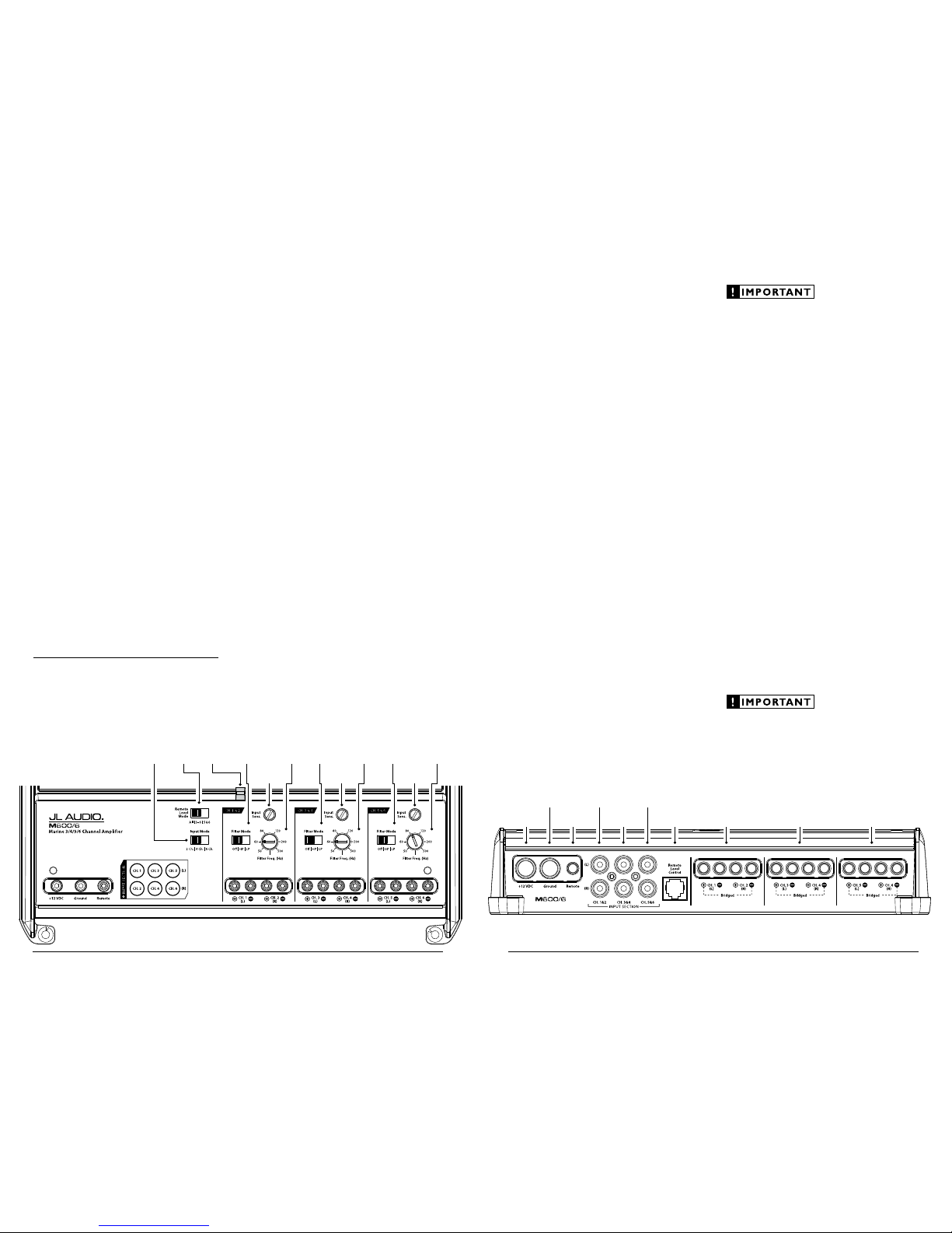
Status
LED
(pg. 11)
Ch. 1 & 2 Filte r
Frequency
Selector
(pg. 8)
Ch. 1 & 2
Filter Mode
Selection
(pg. 8)
Ch. 1 & 2 Inp ut
Sensitivity Control
(pg. 7)
Remote
Level Mode
Switch
(pg. 9)
Input
Mode
Switch
(pg. 7)
Ch. 3 & 4 Filte r
Frequency
Selector
(pg. 8)
Ch. 3 & 4
Filter Mode
Selection
(pg. 8)
Ch. 3 & 4 Inp ut
Sensitivity Control
(pg. 7)
Ch. 5 & 6 Filte r
Frequency
Selector
(pg. 8)
Ch. 5 & 6
Filter Mode
Selection
(pg. 8)
Ch. 5 & 6 Inp ut
Sensitivity Control
(pg. 7)
Remote Turn-On
Connector
(pg. 6)
Chassis Ground
Connector
(pg. 5)
Channels 1 & 2
Preamp Input Jacks
(pg. 7)
Channels 5 & 6
Preamp Input Jacks
(pg. 7)
+12 V Power
Connector
(pg. 5)
Channels 5 & 6
Speaker Outputs
(pg. 10)
Channels 3 & 4
Speaker Outputs
(pg. 10)
Channels 1 & 2
Speaker Outputs
(pg. 10)
Jack for
Remote Level
Control Knob
(pg. 9)
Channels 3 & 4
Preamp Input Jacks
(pg. 7)
4 | JL Audio - M600/6 Owner’s Manual
5
POWER CONNECTIONS
Before installing the amplifier, disconnect the
negative (ground) wire from the vessel’s battery.
This will prevent accidental damage to the system,
the vess el and your body during inst allation.
The M60 0/6’s “+12 VD C” and “Ground”
connect ions are designed to accept 4 AWG
power w ire. 4 AWG is the required wire size for
this amplifier.
If you are installi ng the M600/6 w ith other
amplif iers and wish to use a single main power
wire, use 2 AWG or 1/0 AWG main power wire
(depending on the overall current demands of all
the amplifiers in the system). This 2 AWG or
1/0 AWG power wire should terminate into a
fused distribution block mounted as close to
the ampl ifiers as po ssible (within 12 i nches /
30cm of wire length). The fused output of the
distribution block will connect to the M600/6
with 4 AWG power wire. JL Audio ECS
fused distribution blocks are recommended
(XD-FDBU-2 and XD-FDBU-4)
Note: Smaller AWG numbers mean bigger
wire a nd vice-versa (1/0 AWG is the large st, 2
AWG is smaller, then 4 AWG, then 8 AWG, etc.).
To connect the power wires to the amplifier,
first back out the set screw on the top of the
terminal block, using the supplied 2.5 mm hex
wrench. S trip 1/2 inch (12 mm) of in sulation from
the end of each wire and insert the bare wire into
the terminal block, seating it firmly so that no
bare wire is exposed. While holding the wire in
place, tighten the set screw firmly, taking care not
to strip the head of the screw.
The ground connection should be made using
the sa me gauge wire as the power connect ion.
Any wires run through barriers must
be protected with a high qualit y rubber
grommet to prevent da mage to the
insulation of the wire. Fai lure to do so
may result in a dangerous short circuit.
Many vessels employ small (10 AWG - 6 AWG)
wire to connect the alternator’s positive
connection to the battery. To prevent voltage
drops, this wire should be upgraded to 4 AWG
when installing a mplifier systems with mai n
fuse rat ings above 60A.
It is common for the alternator to be grounded
through its chassis. If the alternator is not
grounded through its c hassis and in stead employs
a smal l (10 AWG - 6 AWG) wire to con nect to
ground, this wire should also be upgraded to 4
AWG when installing amplifier systems with main
fuse r atings above 60A .
FUSE REQUIREMENTS
It is absolutely vital that the main power
wire(s) to the amplifier(s) in the system be
fused within 18 inche s (45 cm) of t he positive
battery post connection. The fuse value at each
power wire should be high enough for all of the
equipment being run from that power wire. If
only the M600/6 is being run from that power
wire, we recommend a 50A fu se be used.
If fusing the amplifier near its power
connections (when more than one amp is being
run f rom the main p ower wire), use a 50A f use.
MAX I™ (big plastic- body) fuses
are recommended.
PRODUCT DESCRIPTION
The JL Audio M600/6 is a six-channel,
full-range audio amplifier utilizing JL Audio
NexD™ u ltra-high speed switching tec hnology to
deliver out standing f idelity and ef ficiency.
The M60 0/6 can be operated wit h a wide
variet y of source un its and system c onfiguration s.
TYPICAL INSTALLATION SEQUENCE
The following represents the sequence
for a typical amplifier installation, using
an af termarket sou rce unit. Additi onal
steps and different procedures may be
required in some applications. If you
have any questions, please contact your
authoriz ed JL Audio dealer for assistance .
1) Disconnec t the negative b attery post
connection and secure the disconnected cable
to prevent accidental re-connection during
insta llation. This step is not optional.
2) Run 4 AWG power wire from the battery
location to the amplifier mounting location,
taking care to route it in such a way that it
will not be damaged and will not interfere
with vessel operation. Use 4 AWG or larger
power wire and a power distribution block if
additiona l amplifiers are being ins talled wit h
the M600/6.
3) Con nect power wire t o the positive bat tery
post. Fuse the wire with an appropriate fuse
block (and con nectors) within 18 inches (45
cm) wire length of the positive battery post.
This f use is essentia l to protect the vessel. Do
not install the fuse until the power wire has
been securely connected to the amplifier.
4) Connect negat ive power wire to t he negative
battery post. Use t he same size p ower
wire as the wire connected to the “+12 V”
connection (minimum 4 AWG).
5) Run signal cables and remote turn-on wi re
from the source unit to t he amplifier
mounting location.
6) Run speaker cable from the speaker systems
to the a mplifier mounti ng location.
7) S ecurely mount the amplifier.
8) Connect the positive a nd negative power
wires to the amplifier. A fuse near the
amplifier is not necessary if the M600/6 is the
only device being run from the fused main
power wire . If the fus ed main power w ire is
shared by the M600/6 and other amplifiers
or devices, fuse each amplifier/device
within 12 inches (30 cm) of wire length,
via a fused distribution block or multiple
indiv idual fuse bloc ks/on-board fuses .
9) Connect the remote turn-on wire
to the a mplifier.
10) Con nect the input ca bles to the ampl ifier.
11) Connect t he speaker cab les to the ampli fier.
12) Carefully review the amplifier’s control
settings to make sure that they are set
according to the needs of the system.
13) Instal l the power wire fuse (50A for a
single M600/6) and reconnect the negative
battery post terminal. Install the fuse (50A)
near t he amplifier (if applicable).
14) Turn on the source un it at a low level
to double-check that the amplifier is
config ured correct ly. Resist t he temptation
to crank it up until you have verified the
control set tings.
15) Make necessary adjustments to the input
sensitivity controls to obtain the right
overall output and the de sired balance
in the system. See Appendix A (page 14)
for the recommended input sensitivity
setting method.
16) Enjoy the fruits of your labor with your
favorite music .
6 | JL Audio - M600/6 Owner’s Manual
7
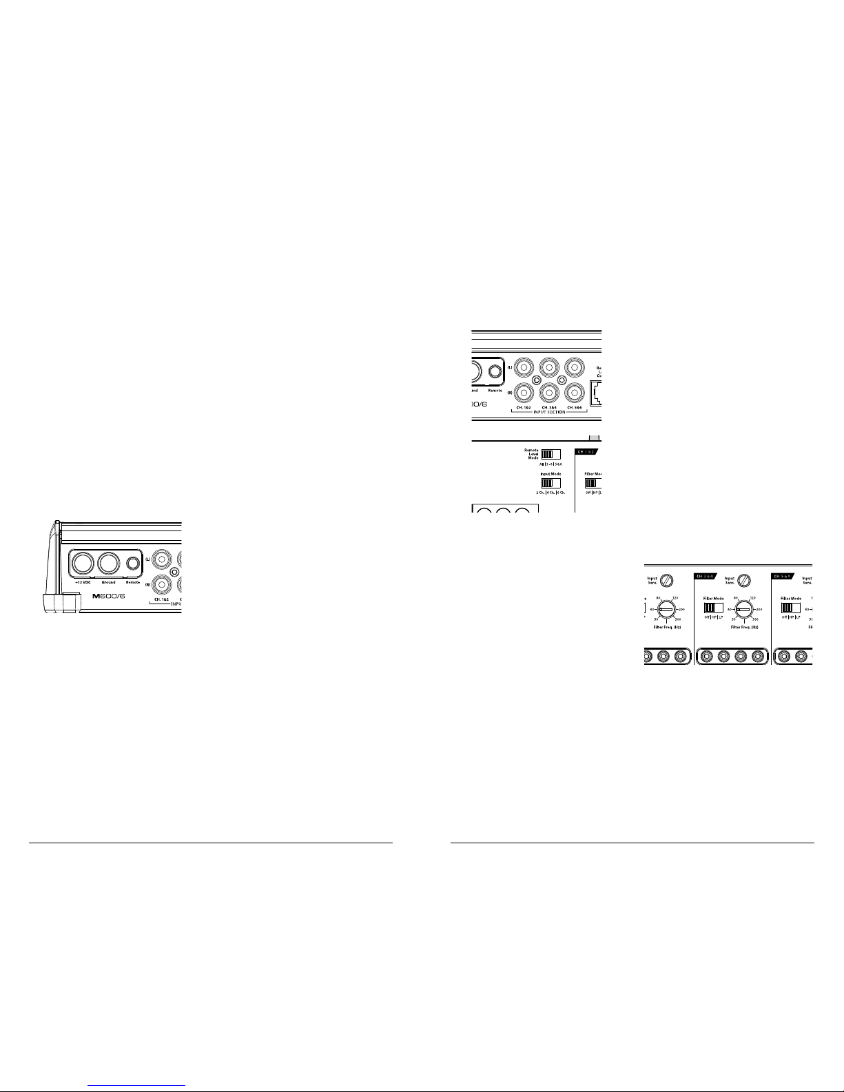
INPUT SECTION
The M600/6’s input section allows you to send
signals to the amplifier section through the use
of two, fou r or six dif ferential-balanc ed inputs.
Input connec tions are via up to three pa irs of
tradit ional RCA-type ja cks.
If you w ish to send six d iscrete channe ls into
the M60 0/6, simply use al l six inputs a nd set the
“Input Mode” s witch in the “6 Ch.” position.
If you wish to feed all six channels by using
only four channels of full-range input, set the
“Input Mode” s witch in the t o “4 Ch.” and use
only the inputs to channels 1, 2, 3 & 4. In this
mode, channels 5 & 6 will operate with a sum of
the 1 & 3 and 2 & 4 input si gnals, respe ctively.
If you wish to feed all six channels by using
two channels of full-range input plus two
channels of low-frequency input (subwoofer
output from the source unit), f irst set the “Input
Mode” switch to “6 Ch.”. Next, it will be necessary
to split the full-range signals with y-adaptors and
feed these signals into the inputs to channels 1 &
2 and 3 & 4. The dedicated subwoofer signal will
be sent to channels 5 & 6.
If you wish to use only two channels of
input to del iver signal to a ll six ampl ifier
channel s, set the “Input Mode” switch to “2
Ch.” and use on ly the inputs to c hannels 1 &
2. In this mode, Channels 3 & 5 will operate
with the channel 1 signal and channels 4 &
6 wil l operate with the Channel 2 signal.
Input Voltage Range:
The M60 0/6’s input sect ions are designed to
accept signal voltages from 100mV – 4V. This
will accommodate all preamp level signals and
many spe aker level signa ls.
To use speaker-level sources, simply splice the
speaker output wires of t he source unit onto a
pair of RCA plugs for each input pair. (or use JL
Audio part XD-CLRAIC2-SW) No “line output
converter” is needed in most cases.
If you find that the output cannot be reduced
sufficiently with a direct speaker level signal
applied to the amplifier, you may use a “line
output conver ter” to reduce the signal level.
INPUT SENSITIVITY CONTROLS
The control s labeled “Input Se ns.” located in
each channel section can be used to match the
source unit’s output voltage to the input stage of
each pai r of amplifie r channels for ma ximum
clean out put. Rotating t he control clockw ise will
result in higher sensitivity (louder for a given
input voltage). Rotat ing the control counterclockwise will result in lower sensitivity (quieter
for a given input voltage.)
To properly set the amplifier for maximum
clean out put, please refer to Appendix A (page
14) in this manual. After using this procedure,
you can then adjust any or all “Input Sens .”
levels downward if this is required to achieve the
desired system balance.
Do not increase any “Input Sens.” setting for
any channel(s) of any amplifier in the system
beyond the maximum level established duri ng
the procedure outlined in Appendix A (page 14).
Doing so w ill result i n audible distort ion and
possible spe aker damage.
TURNON LEAD
The M600/6 uses a conventional +12V remote
turn-on lead, typically controlled by the source
unit's remote turn-on output. The amplifier will
turn on when +12V is prese nt at its “Remote”
input and turn off when +12V is switched off. If
a source u nit does not have a dedicated remote
turn-on output, the amplifier’s turn-on lead can
be connec ted to +12V via a switch that derives
power from an ignition-switched circuit.
The M60 0/6’s “Remote” turn-on connector is
designed to accept 18 AWG – 12 AWG wire. To
connect the remote turn- on wire to the a mplifier,
first back out the set screw on the top of the
terminal block, using the supplied 2.5mm hex
wrench. Strip 1/2 inch (12mm) of wire and insert
the bar e wire into the terminal bloc k, seating it
firmly so that no bare wire is exposed. While
holding t he wire in t he terminal, tighten the se t
screw firmly, taking care not to strip the head of
the screw and making sure that the wire (not the
insulat ion) is firmly gripped by the set screw.
 Loading...