

JL Audio M-Series M4300 Owner's Manual
Thank you for purchasing a JL Audio amplifier for
your marine sound system.
Your amplifier has been designed and manufactured to exacting
standards in order to ensure years of musical enjoyment in your vessel.
For maximum performance and extended warranty
coverage, we highly recommend that you have your new amplifier
installed by an authorized JL Audio dealer. Your authorized
dealer has the training, expertise and installation equipment to ensure
optimum performance from this product. Should you
decide to install the amplifier yourself, please take the time
to read this manual thoroughly so as to familiarize yourself
with its installation requirements and setup procedures.
If you have any questions regarding the instructions in this
manual or any aspect of your amplifier’s operation, please contact your
authorized JL Audio dealer for assistance. If you need further assistance,
please call the JL Audio Technical Support Department
at (954) 443-1100 during business hours.
OWNER’S MANUAL
M4300
four-channel marine amplifier
PLANNING YOUR INSTALLATION
It is important that you take the time to read
this manual and t hat you plan out your
installation carefu lly. The following are some
considerations that you must take into account
when planning your installation.
Cooling Ef ficiency Consi derations:
The outer shell of your JL Audio amplifier
is designed to remove heat from the amplifier
circuit ry. For optimum cooling per formance,
this outer shell should be exposed to as large a
volume of air as possible. Enclosing the a mplifier
in a smal l, poorly ventilated cha mber can
lead to excessive heat build-up and degraded
performance. If an installation calls for an
enclosure around the amplifier, we recommend
that this enclosure be ventilated with the aid
of a fan. In normal applications, fan-cooling
is not necessa ry.
Mounting the amplifier upside down is
strongly discouraged.
If mounting the ampli fier under a seat,
make sure t here is at least 1 inch (2.5 cm) of
space above the amplif ier’s outer shell to permit
proper cooling.
Safety Considerations:
Your amplifier needs to be installe d in a dry,
well-ventilated envi ronment and in a manner
which does not i nterfere with your vess el’s factory
insta lled electronic dev ices. You should al so take
the time to s ecurely mount the ampli fier using the
supplied screws so that it does not come loose in
the event of a col lision or a sudden jolt to the vessel.
Stupid Mistakes to Avoid:
• Check before drilli ng any holes in your vessel to
make sure that you will not be drilling through
the hull, a fuel ta nk, fuel line, w iring harness or
other vital vessel s ystem.
• Do not run system wir ing outside or underneath
the vessel. This is an ext remely dangerous
practice which can result in severe damage to
your vessel a nd person.
• Protect all system wires from sharp edges
(metal, fiberglass, etc.) by careful ly routing
them, ty ing them down and using grommets
and loom where appropriate.
• Do not mount the amplifier in the engine
compart ment or in any other area that w ill
expose t he amplifier circuitry to the elements.
While this amplif ier is specially desig ned
for marine applications, it is not waterproof
and it should not be mou nted where it is
likely to get wet.
JL AUDIO M4300 3
PROTECT YOUR HEARING!
We value you as a long-term customer. For
that reason, we urge you to practice restraint in
the operation of this produc t so as not to damage
your hearing and that of others in your vessel.
Studies have shown that continuous exposure to
high sound pressure levels can lead to permanent
(irreparable) hearing loss. This and a ll other
high-power ampli fiers are capable of producing
such high sound pressure levels when connected
to a speaker system. Please limit your conti nuous
exposure to high volume levels.
While driving, operate your aud io system i n
a manner that stil l allows you to hear necessary
noises to operate your vessel safely (horns,
sirens, etc.).
SERIAL NUMBER
In the event that your ampli fier requires
service or is ever stolen, you will need to have
a record of the product’s serial number. Please
take the time to enter that number in the space
provided below. The serial number can be fou nd
on the bottom panel of the amplifier and on the
amplifier packaging.
Serial Number:
INSTALLATION APPLICATIONS
This ampl ifier is designed for oper ation in
vessels w ith 12 volt, negative-ground electr ical
systems. Use of this product in vessels with
positive ground and/or voltages other than 12V
may result in damage to the product and will void
the warranty.
This product is not cert ified or approved for
use in aircraft.
Do not attempt to “ bridge” the outputs of this
amplif ier with the outputs of a second amplif ier,
including an identical one.
2 JL AUDIO M4300
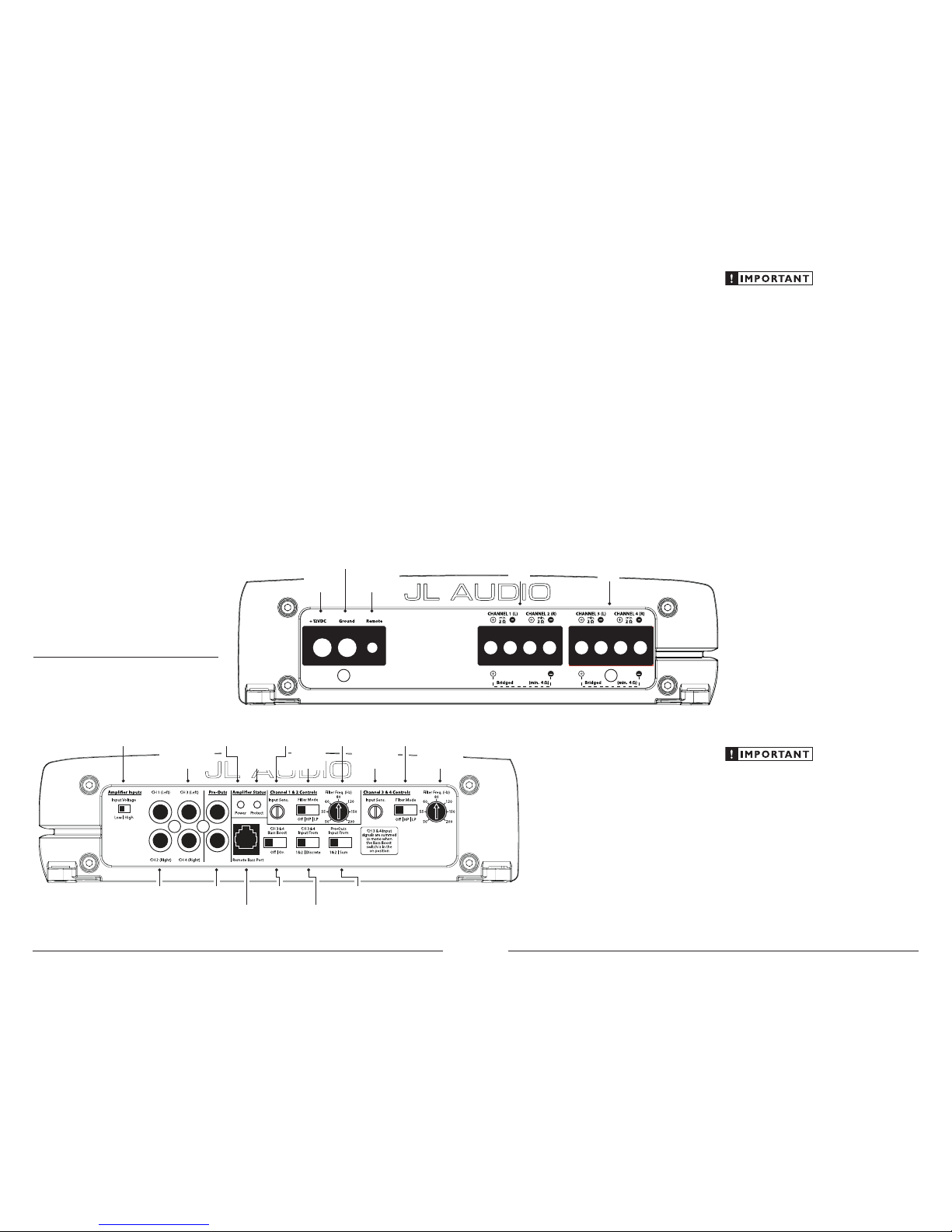
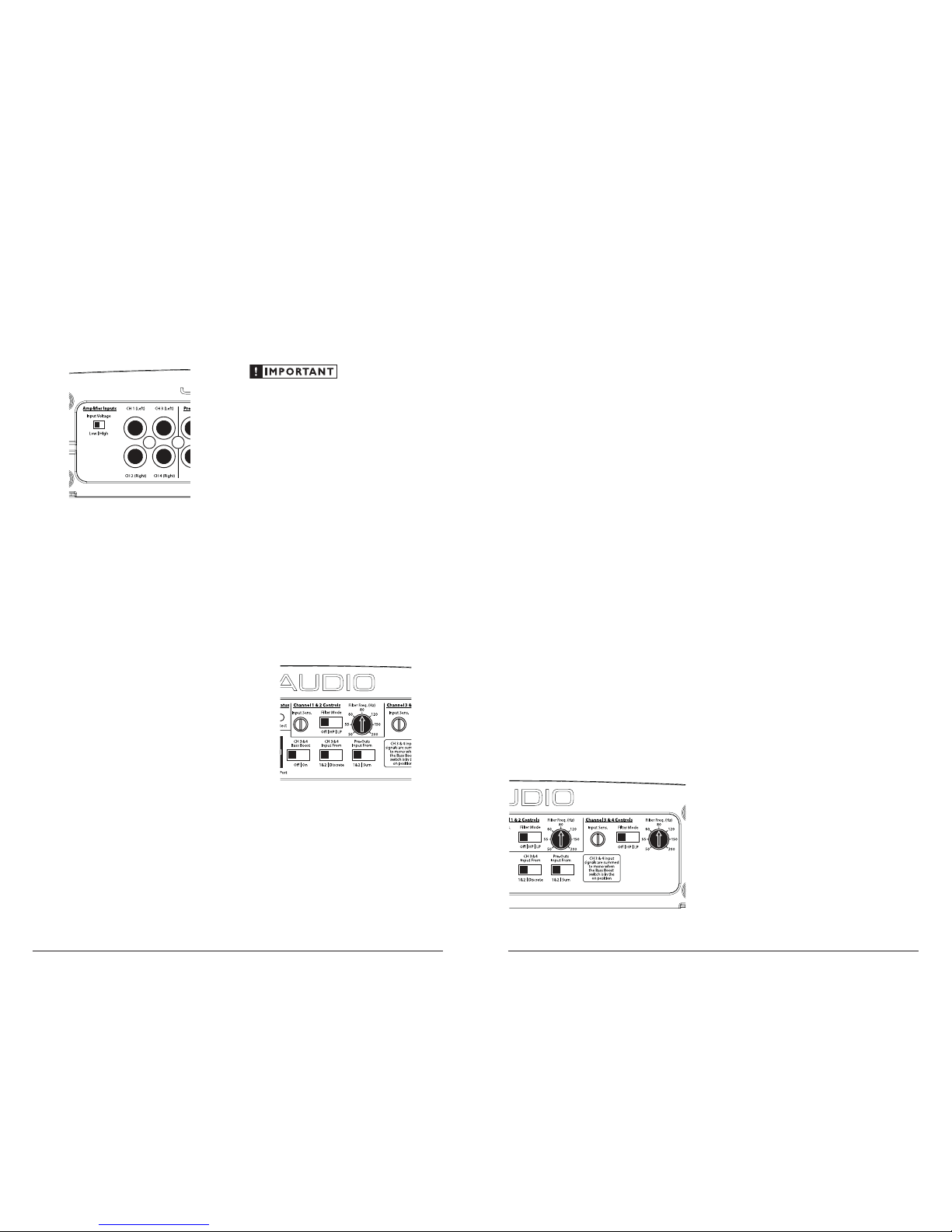
Input Voltage
Selection
(pg. 6)
Channels 3 & 4
Preamp Input Jacks
(pg. 6)
Channels 1 & 2
Preamp Input Jacks
(pg. 6)
Left & Right
Preamp Output
Jacks
(pg. 8)
Ch. 3 & 4
Bass Boost
On/Off Switch
(pg. 8)
Pre-Out Signal
Selection Switch
(pg. 8)
Power
Status
Indicator
(pg. 10)
Jack for
Remote Bass
Control Knob
(pg. 8)
Ch. 3 & 4
Input Selection
Switch
(pg. 6)
Ch. 1 & 2 Filter
Frequency
Selector
(pg. 7)
Ch. 1 & 2 Input
Sensitivity
Control
(pg. 6)
Protection Status
Indicator
(pg. 10)
Ch. 1 & 2
Filter Mode
Selection
(pg. 7)
Ch. 3 & 4
Filter Mode
Selection
(pg. 7)
Ch. 3 & 4
Input Sensitivity
Control
(pg. 6)
Ch. 3 & 4
Filter Frequency
Selector
(pg. 7)
Remote Turn-On
Connector
(pg. 5)
Chassis Ground
Connector
(pg. 5)
+12 V Power
Connector
(pg. 4)
Channels 3 & 4
Speaker Outputs
(pg. 8)
Channels 1 & 2
Speaker Outputs
(pg. 8)
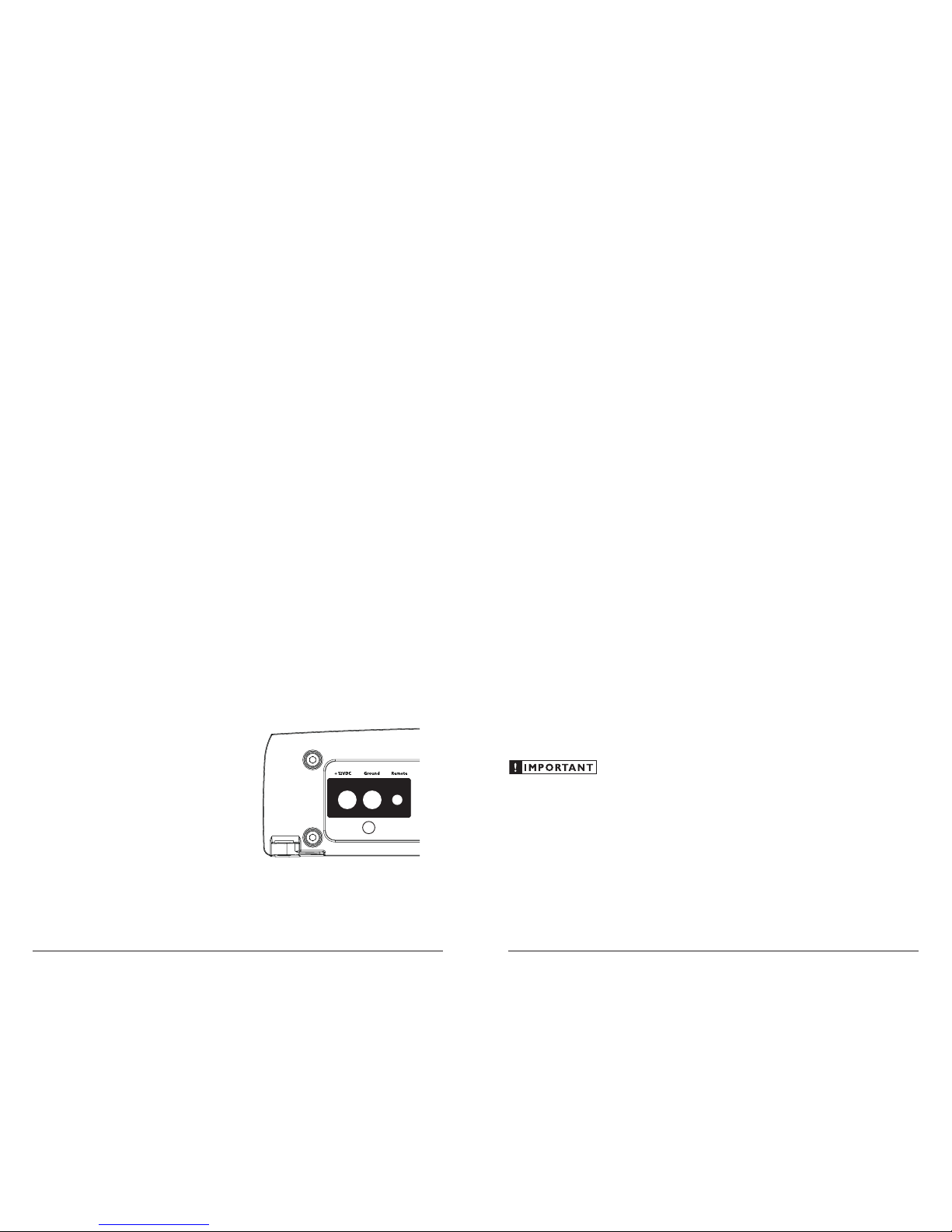
The M4300’s “+12 VD C” and “Ground”
connections are designed to accept 8 AWG 4 AWG power wire. 8 AWG is a minimum power
wire size for this amplifier.
If you are install ing the M4300 with other
amplif iers and wish to use a single main power
wire, use 4 AWG or larger main power wi re
(depending on the overall current demands of all
the ampli fiers in the system). This 4 AWG or
larger power w ire should terminate into a
distribution block mounted as close to t he
amplif iers as possible a nd should connect to the
M4300 wit h 8 AWG - 4 AWG power wire.
Note: Smaller AWG numbers mean bigger wire
and vice-versa (1/0 AWG is the largest, 2 AWG is
smaller, then 4 AWG, then 8 AWG, etc.).
To connect the power wires to the a mplifier,
first back out the set screw on the top of t he
termina l block, using the supplied 2 .5 mm hex
wrench. St rip 1/2 inch (12 mm) of insu lation from
the end of each w ire and insert the bare wire i nto
the termi nal block, seating it f irmly so that no
bare wire is exposed . While holding the wi re in
place, tig hten the set screw fir mly, taking care not
to strip the head of the screw.
The ground connection should be made using
the same gau ge wire as t he power connection.
Any wires run th rough barriers must be
protected with a high quality rubber grom met
to prevent damage to the insulation of the wire.
Failure to do so may result in a dangerous short
circuit.
Many vessels employ small (10 AWG - 6 AWG)
wire to connect the alternator’s positive
connection to the batter y. To prevent voltage
drops, this wire should be upgraded to 4 AWG
when installing amplif ier systems with main
fuse ratings above 60A.
It is common for the alternator to be grounded
through its chassis. If the a lternator is not
grounded t hrough its chassis a nd instead employs
a small (10 AWG - 6 AWG) wire to con nect to
ground, this wire should also be upgraded to 4
AWG when installing ampli fier systems with main
fuse rat ings above 60A.
FUSE REQUIREM ENTS
It is absolutely vital that the main power
wire(s) to the ampli fier(s) in the system be
fused w ithin 18 inches (45 cm) of the positive
battery post connection. The fuse va lue at each
power wire shou ld be high enough for all of the
equipment being run from that power wi re. If
only the A430 0 is being run from t hat power wire,
we recommend a 40A f use be used. AFS (min i
blade fuse), AGU (big gla ss fuse) or MaxiFuse™
(big plastic-body fus e) types a re recommended.
No fuse is required or recommended direct ly
before the ampl ifier power connection. If one is
desired, we recommend the u se of a 40A fuse.
TURNON LE AD
The M4300 uses a conventiona l +12V remote
turn-on lead, ty pically controlle d by the source
unit’s remote tur n-on output. The amplif ier will
turn on when +12V is present at its “Remote”
input and turn off when +12V is switched off. If
a source unit does not have a dedic ated remote
turn-on out put, the amplifier’s turn-on lead can
be connected to +12V via a switch that derives
power from an ig nition-switched circuit.
The M4300’s “Remote” turn-on connector is
designed to accept 18 AWG – 12 AWG wire . To
connect the remote turn-on wire to t he amplif ier,
first back out the set screw on the top of t he
termina l block, using the supplied 2 .5mm hex
wrench. Strip 1/2 inch (12mm) of wire and insert
the bare wire into the termina l block, seating it
firmly so that no bare wire is exposed. While
holding the w ire in the termina l, tighten the set
screw firmly, tak ing care not to strip the he ad of
the screw and maki ng sure that the wire (not the
insulat ion) is firmly gripped by the set screw.
JL AUDIO M4300 5
PRODUCT DE SCRIPTION
The JL Audio M4300 is a four-channel,
full-range audio amplifier utilizing patented
Absolute Symmetry™ Class A/ B technolog y
for all cha nnels.
The M4300 can be operate d with a w ide
variet y of source units and system configurat ions.
TYPICAL I NSTALLATION SEQUE NCE
The followi ng represents the sequence for a
typical ampli fier installation, usi ng an aftermarket
source unit. Additional steps a nd different
procedures may be required in some applications.
If you have any quest ions, please contact your
authoriz ed JL Audio dealer for assist ance.
1) Disconnect the negative battery post
connection and secure the disconnected cable
to prevent accidental re-connection dur ing
installation. This step is not optional!
2) Run positive a nd negative power w ire
(minimum 8 AWG) from from the bat tery
location to the a mplifier mounting location,
taki ng care to route it i n such a way that it
will not be damaged and will not interfere
with vessel operation. Use 4 AWG or larger
power wire and a power dist ribution block
if additional ampli fiers a re being installed
with the M4300.
3) Connect power wire to the positive battery
post. Fuse t he wire w ith an appropr iate fuse
block (and connectors) within 18 inches (45
cm) wire length of the positive battery post.
This fuse is essential to protect the vessel.
Do not insta ll the f use until the power w ire
has been connected to the amplif ier.
4) Connect negat ive power wire to the negative
battery post. Use t he same size power
wire as t he wire con nected to t he “+12V ”
connection (minimum 8 AWG).
5) Run signa l cables and remote turn-on wire
from the source unit to t he amplif ier
mounting location.
6) Run speaker wire from t he speaker system
to the ampli fier mount ing locat ion.
7) Securely mount t he amplif ier using the
supplied screws.
8) Connect the positive and negative power
wires to the amplif ier. A fuse near the
amplif ier is not necessary.
9) Connect the remote turn-on wire to
the amplifier.
10) Connec t the input cables to the ampl ifier.
11) Con nect the speaker w ires to the amplif ier.
12) Careful ly review the ampli fier’s control
settings to make sure that they are set
according to the needs of t he system.
13) Install power wire f use (40A for a single
M4300) and recon nect the negative
battery post terminal.
14) Turn on the source u nit at a low level
to double-check that the amplifier is
configured correctly. Resist the temptation
to crank it up until you have verified the
control set tings.
15) Make necessa ry adjust ments to the input
sensitiv ity controls to obtai n the rig ht
overall out put and the desired ba lance in the
system. See Appendix A (page 12)
for the recommended input sensit ivity
setti ng method.
16) Enjoy the f ruits of your labor wit h your
favorite music.
POWER CONNECTIONS
Before installing the amplifier, disconnect the
negative (ground) wire from the vessel's battery.
This will prevent ac cidental damage to t he system,
the vessel and your body during i nstallation.
4 JL AUDIO M4300
Do not increase any “Input Sens.” setting for
any channel(s) of any amplifier in the system
beyond the ma ximum level established during
the procedu re outlined in Appendix A (page
14). Doing so will result in audible d istortion
and possible speaker damage.
FILTER CONTROLS
Most speakers are not designed to reproduce
the full range of frequencies audible by the
human ear. For this reason, most spea ker
systems are comprised of mu ltiple speakers, each
dedicated to reproducing a specific f requency
range. Filters are used to select which frequenc y
range is sent to each section of a spea ker system.
The division of frequency ra nges to different
speakers can be done w ith passive filters (coils
and/or capacitors between the amplifier outputs
and the speakers), which a re acceptable and
commonly us ed for filtering between midrange speakers and tweeters. Filteri ng between
subwoofer systems and satellite speaker sy stems
is best done with active filters, which cut off
frequency c ontent at the input to t he amplifier.
Active filters are more stable than passive filters
and do not introduce extra neous resistance,
which can degrade subwoofer perfor mance.
The active filter bu ilt into each channel section
of the M4300 c an be used to eliminate potent ially
harmf ul and/or undesired frequencies from
maki ng their way through the ampli fier sections
to the speaker(s). This serves to improve tonal
balance and to avoid distortion and possible
speaker failure. Correct use of these filters can
substant ially increase the longevity and f idelity
of your audio system.
1) “Filter Mode” Control: The M4300 employs a
12dB per octave filter for each pair of channels
(one filter for channels 1&2 and anot her filter
for channels 3&4). Each of these f ilters can
be configured independently into one of two
filter types or defeated completely by way of the
three-position “Filter Mode” switches:
“Off”: Defeats t he filter completely, allowing
the full range of f requencies present at the
inputs to feed the amplifier. This is useful
for systems ut iliz ing outboa rd crossovers or
requiri ng ful l-range reproduction from one or
both of the M4300’s channel pairs.
“LP” (Low-Pass): Configures the filter to
attenuate frequencies above the selected filter
frequency at a rate of 12dB per octave. This is
useful for connection of subwoofer(s) to one
or both of the M43 00’s channel pairs in a
bi-amplif ied system.
“HP” (High-Pass): Configures the filter to
attenuate frequencies below the selected f ilter
frequency at a rate of 12dB per octave. This is
usefu l for connection of component spea kers to
one or both of the M43 00’s channel pairs in a
bi-amplif ied system.
2) “Filter Freq. (Hz)” The filter frequency
markings surrounding this rotary control
are for reference purposes a nd are generally
accurate to within 1/3 octave or b etter. If you
would like to select the filter cutoff frequency
with a higher level of precision, consult t he
chart in Appendix B (page 15).
Tun in g Hi nt: If you are using the M430 0
to drive a subwoofer system (“LP” mode), a
component satellite spea ker system (“HP” mode)
or both, 80 Hz is a good baseline “Filter Freq.
(Hz)” setting. After properly adjusting the “Input
Sens.”, as outlined in Appendix A (page 14), you
can fi ne tune the “Filter Freq. (Hz)” control to
achieve the desired system frequenc y response.
JL AUDIO M4300 7
INPUT SECTION
The M4300’s input section al lows you to send
signal to t he amplifier section throu gh the us e of
either two or four differential-balanced inputs.
Input connect ions are via tradit ional
RCA-ty pe jacks.
If you wish to send four discrete channels into
the M4300, simply use a ll four inputs (channels
1 & 2 and channels 3 & 4) and set t he “CH 3&4
Input From” switch to “Discrete”.
If you wish to feed all four channels by using
only two cha nnels of input, set the “CH 3&4
Input From” switch to “1&2 ” and use only the
inputs to channels 1 & 2.
Input Voltag e Range:
A wide range of signal i nput voltages ca n be
accommodated by the M430 0’s input sections
(200mV – 8V). This wide ra nge is split up into
two sub-ranges, accessible via a sw itch located to
the left of t he Input Connectors. Be aware that the
position of th is switch will dictate the sensitiv ity
range for al l four input channels.
The “Low” position on the “Input Voltage”
switch selects an input sensitiv ity range between
200mV and 2V. This means that the “Input
Sens.” rotary control w ill operate with in that
voltage window. If you are using a sou rce unit
with conventional preamp-level outputs, this is
most likely the position that you will use.
The “High” position on the “Input Voltage”
switch selects an input sensitiv ity range between
800mV and 8V. This is usef ul for certain highoutput preamp level signals as well as speakerlevel outputs from source units not equipped w ith
preamp-level out puts.
To use speaker-level sources, splice the speaker
output wires of the source unit onto a pair of RCA
plugs for each input channel pa ir. No line output
converter is needed in most cases.
The output of the ampl ifier will decre ase for
a given input volta ge when the “Input Range”
switch is placed in the “High” position.
Conversely, the output will be higher with the
switch in t he “Low” position. Wh ile this may
sound counter-intuitive, it is consistent with the
descriptions in this sect ion.
INPUT SENSITIVITY CONTROLS
Once the appropriate “Input Voltage” range
has been selected, t he controls labeled “Input
Sens.” located in each “Channel Controls”
section can be used to match the sou rce unit’s
output voltage to the input stage of each pair of
amplif ier channels for maximum clean output.
Rotating t he control clockwise will re sult in
higher sensitivit y (louder for a given input
voltage). Rotating t he control counter-clockw ise
will re sult in lower sensitivity (quieter for a given
input voltage.)
To properly set the ampli fier for maximum
clean output, please refer to Appendix A (page
14) in this manual. After using this procedure,
you can then adjust any or all “Input Sens.”
levels downward if this is required to achieve the
desired system balance.
6 JL AUDIO M4300
 Loading...