

Page 1
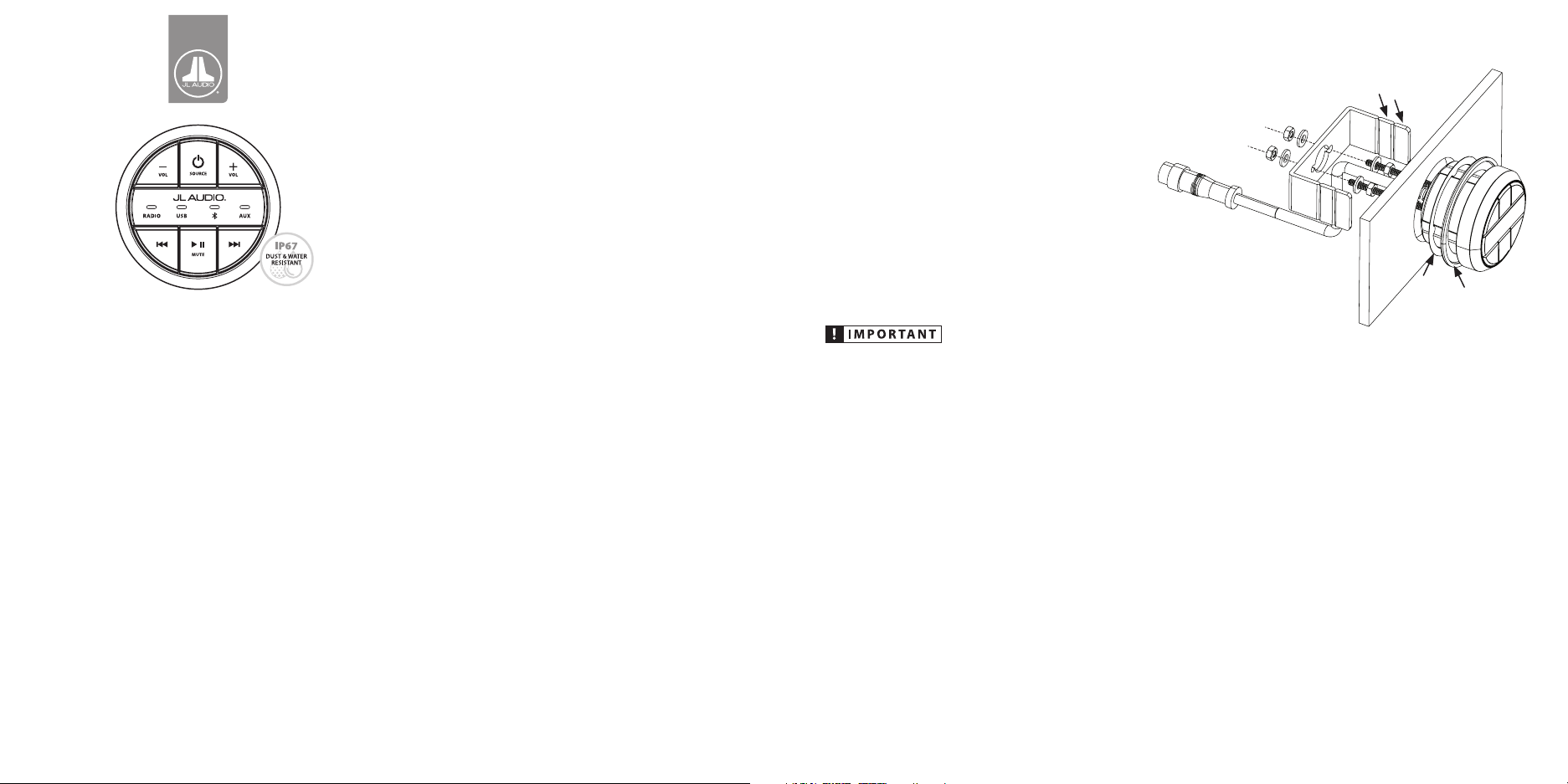
MMR-20-BE
MediaMaster® Wired Remote Controller
Product Description
The MMR-20-BE is a water-resistant
(IP67 rated), wired remote controller designed
to add auxiliary control functionality to
MediaMaster® source units. Depending
on your system layout, you may add up to
three MMR-20-BE remote controllers to a
single source unit. Each MMR-20-BE can be
connected up to 75 ft. (22.8 m) away from its
source unit. A Y-splitter and remote extension
cables are sold separately and available in
different lengths to suit different mounting
locations.
What’s Included
(1) MMR-20-BE wired remote controller
(1) Lipped gasket (preinstalled)
(1) Flat gasket (optional)
(2) Stainless steel threaded studs
(4) Stainless steel nuts (7 mm)
(4) Stainless steel washers
(1) Aluminum C-bracket
(1) User Manual
Safety Considerations
• While this product is designed to be waterresistant, it should never be submerged
under water or subjected to high-pressure
water spray.
• Do not mount in areas of extreme heat.
• Ensure this product is securely installed so
that it does not come loose in the event
of a collision/sudden jolt or as a result
or repeated vibrations during normal
operation.
• Check before drilling to make sure that you
will not be drilling into a fuel tank, gas/brake
line, wiring harness, or other vital system.
• Secure all wiring as needed, using cable
ties or wire clamps to protect them from
moving parts and sharp edges.
Mounting & Installation
A 2-inch (50 mm) hole is required for
mounting, along with adequate rear access
to secure/tighten the hardware. The included
hardware accommodates installations in flat
panels up to 1.5-inches (38 mm) thick.
The C-bracket is designed with break lines
to allow adjustment for different mounting
panel thicknesses. To remove a leg section,
use pliers and bend back and forth at
a break line to separate. Be mindful of
resultant sharp edges and file if necessary.
Make sure to carefully plan the routing of
the remote’s connection cables prior to
cutting or drilling any panels.
1. Select an appropriate mounting location
and cut a 2-inch (50 mm) hole using an
appropriate tool/hole saw.
2. The preinstalled lipped gasket can be used
for most installations or where an existing
mounting hole may be slightly larger than
2-inches. If you desire a reduced profile
appearance, you may replace the lipped
gasket with the optional flat gasket.
3. Apply thread sealer (not included) onto
the threaded studs and insert them into
the inserts at the rear of the MMR-20-BE,
and hand tighten.
Remove
leg sections
as neeeded
Flat
Lipped
Gasket
Gasket
(optional)
(preinstalled)
4. Install a nut and washer near the middle
section of each stud (see diagram) and
place the MMR-20-BE into the mounting
hole.
5. From behind the mounting panel, slide
the C-bracket onto the threaded studs and
press it forward, towards the MMR-20-BE
6. Apply thread sealer and adjust the position
of the previously installed nuts and
washers to support the C-bracket while
still allowing the legs to of the C-bracket
to press against the rear of the mounting
panel.
7. Apply thread sealer and install a remaining
nut and washer onto each stud. Tighten
the C-bracket to the mounting panel.
Page 2

Thin Panel Installation Example
Route the cable through the C-bracket as shown to
avoid chafing/damage (with the strain relief extended
past the center hole).
Thick Panel Installation Example
Route the cable as shown to avoid chafing/damage
(not through the center hole in the C-bracket).
Connection Cables
Connection cables (sold separately) are
available in 6 ft. (MMC-6) and 25 ft. (MMC-25)
lengths to suit different mounting locations.
A Y-splitter (MMC-2Y) (sold separately) may be
used to connect an additional remote to a
single source unit.
Each remote controller may be connected
a maximum 75 ft. (22.8 m) of cable length
away from its source unit. Remote controllers
and cables utilize a 5-pin connector with a
watertight threaded collar to securely mate
their ends together. Connectors are keyed
and must be aligned to fit properly. Once
connected, make sure that cables are securely
routed using cable ties or wire clamps, keeping
connections away from areas where they could
be submerged in water.
LED Source Indicators
Blue LED indicators on the front of the remote
controller are used to report the currently
selected source. Pressing the button
will cycle through each source option (RADIO/
USB/Bluetooth®/AUX).
Since the MMR-20-BE does not incorporate a
display screen, all available tuner options (AM/
FM/WB SiriusXM®) are combined as “RADIO”.
When RADIO is chosen, the last tuner used
will be selected. To change tuners, use the
MediaMaster® source unit.
Control Functions
Below is a list of MMR-20-BE command
functions. The functionality of some controls
will vary depending on the current source and/
or last tuner selected. Note: The MediaMaster®
source unit only accepts commands from the
MMR-20-BE when its display is on a Now
Playing Screen or in the SOURCE: Select
menu screen.
• Press to turn the source unit ON
• Press to cycle through sources (RADIO/USB/Bluetooth®/AUX)
• Press and hold to turn the source unit OFF
• Press to increase volume
• Press to decrease volume
• Press to mute audio (AM/FM/WB SiriusXM®/AUX)
• Press to pause or resume the current selection
(USB/Bluetooth®)
• Press to select the next Favorite (AM/FM/WB SiriusXM®)
• Press to select the next track (USB/Bluetooth®)
• Press and hold to fast-forward (USB)
• Press to select the previous Favorite (AM/FM/WB SiriusXM®)
• Press to select the previous track (USB/Bluetooth®)
• Press and hold to fast-rewind (USB)
MMR-20-BE Backlight Settings
Brightness settings for the MMR-20-BE’s
LEDs and buttons can be accessed in the
MediaMaster® source unit’s System Settings
menu. Adjustments can be set independently
for Day and Night lighting modes.
To access the remote controller backlight
settings on the MediaMaster® source unit:
1. Press and hold to access the
System Settings: Main Menu.
2. Turn to Display and press to enter.
3. Use to select Day Mode or Night
Mode and press to enter.
4. Turn to Brightness and press
to enter.
5. Tur n to Remote Backlight and
press to enter.
6. Turn to adjust the remote’s
brightness and press to set.
IP67 Water Resistance Rating
This product has been tested to withstand
immersion in water, up to 1 meter (3.28 ft.)
deep, for up to 30 minutes (when properly
installed). Note: while designed to be water
resistant, this product should never be
submerged under water for prolonged periods
or subjected to activity that creates pressure on
it that exceeds its depth rating.
2-Year Limited Warranty (U.S.A.)
Visit www.jlaudio.com for warranty details.
For Service Information in the U. S.A. please call JL Audio
customer service: (954) 443-1100 during normal business hours
(Eastern Time) • JL Audio, Inc • 10369 N Commerce Park way,
Miramar, FL 33025
International Warranties:
Products purchased outside the United States of America are
covered only by that country’s distributor and not by JL Audio, Inc.
11-15-2016 • Printed in China
 Loading...