

Page 1

Installation Instructions for
M-MCPv3
fixed-mount fixtures for round pipes
PIPE MOUNTING FIXTURES (FIXED)
FOR ETXv3 ENCLOSED SPEAKER SYSTEMS
Page 2
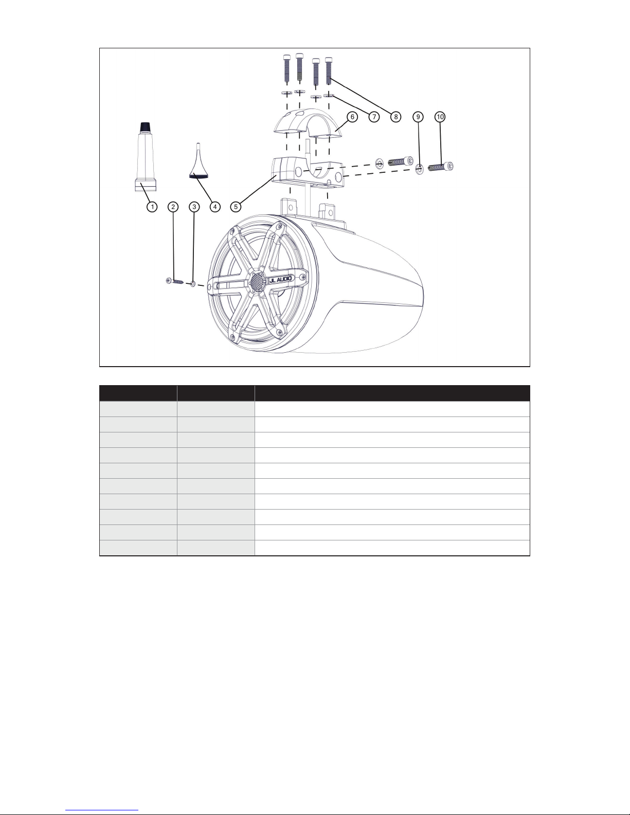
Included Hardware:
BOM ID Quantity Description
1* 1 Silicone Adhesive
2* 12
#8 x 1-1/4” Pan Head Screw
3* 12 #8 Flat Washer
4 2 Loctite® Red read-Locking Compound
5 2 Lower Fixture
6 2 Upper Fixture
7 8 1/4" Split Lock Washer
8 8 1/4 - 20 x 1-1/4” Machine Screw
9 4 5/16" Split Lock Washer
10 4 5/16 - 18 x 1-1/4” Machine Screw
* Supplied with ETXv3 speaker system.
NOTE: The M-MCPv3-2.000 Fixture and M770-ETXv3-SG-WH Enclosed Speaker
System are used in this manual for illustrative purposes only. The fixture
installation steps are the same for all ETXv3 Enclosed Speaker Systems and all
M-MCPv3 fixed-mount fixtures for round pipes.
Page 3
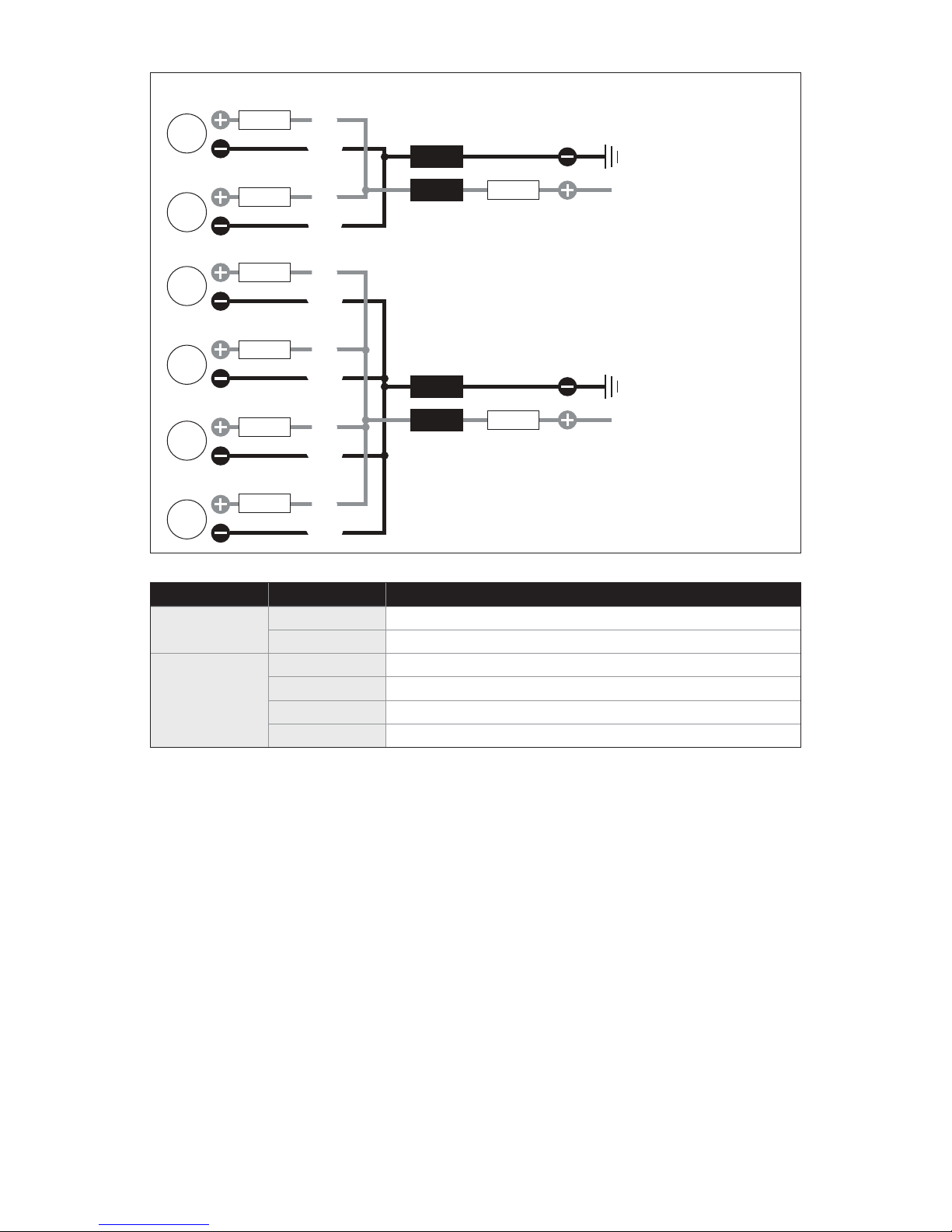
Wiring Information (LED models only):
LED
LED
LED
LED
LED
LED
Fuse
Fuse
Fuse
Fuse
Fuse
Fuse
Blue
Blue
Yellow
Yellow
Blue
Blue
Yellow
Yellow
Blue
Blue
Yellow
Yellow
Blue
Blue
Yellow
Yellow
Blue
Blue
Yellow
Yellow
Blue
Blue
Yellow
Yellow
[GND]
[+12V]
[GND]
[+12V]
Example: One speaker pair of
LED circuits connected in parallel.
Fuse
Example: Two speaker pairs of
LED circuits connected in parallel.
Fuse
Wire Size Wire Color Use
16 AWG
Red/Stripe Speaker Positive (+)
Black/Stripe
Speaker Negative (–)
Red Not Used
20 AWG
Green Not Used
Blue LED Positive (+)
Yellow LED Negative (–)
NOTE: Not all wires may be used in normal applications.
• For marine installations, do not connect the speaker’s LED lights to the vessel’s
navigational lighting circuits.
• For short-circuit protection, install a supplied fuseholder onto EACH speaker’s BLUE (+12V)
LED power connection lead.
• Connect all BLUE (+12V) leads together (parallel) and connect to a switched +12V supply.
Connect all YELLOW (GND) leads together and connect to a negative ground or to the
NEGATIVE battery post.
• We recommend activating the speakers’ LEDs thru a lighting circuit that supplies +12V via
an existing switch. If an existing switched circuit is not available, you may install a dedicated
toggle/rocker style switch that will supply positive (+12V) power. Fuse this connection
according to how many LED circuits you have (LED circuits x 150 mA).
Page 4

Installation Procedure:
1A 1B
OR
ere are two speaker cable routing options. For
applications where the cable cannot be routed
through the pipe, the cable can be passed through
one of the openings on the side of the Lower Fixture.
2 3
Determine the speaker mounting location. Slide a
1/4" Split Lock Washer over each of the four 1/4 - 20
x 1-1/4” Machine Screws, and hand tighten the
screws into the Lower Fixture to temporarily secure
the two xture halves around the pipe.
For applications where the cable can be routed
through the pipe, the cable can be passed through
the opening in the bottom of the Lower Fixture.
Steps 2, 3, and 6 are only necessary for this option.
Adjust the angle of the xture to the desired position,
and mark the location for the cable hole. Remove the
xture assembly, and drill a 5/16" or 3/8" hole on the
mark. If necessary, use a le or sandpaper to smooth
the edges to ensure no sharp edges.
4 5
Align the Lower Fixture to the enclosure. Install (2)
5/16" Split Lock Washers and (2) 5/16 - 18 x 1-1/4”
Machine Screws as pictured. Apply Loctite® Red
read-Locking Compound to each screw end,
them into the Lower Fixture, and fully tighten while
pressing down on the Lower Fixture to ensure no gap.
thread
Have a helper support the enclosure during this
step. Connect the 16 AWG red/stripe (+) and black/
stripe (-) speaker cable exiting the ETXv3 enclosure
to the speaker cable exiting the pipe. For LED
models, connect the 20 AWG blue LED (+) and
yellow LED (-) as illustrated on Page 2.
Page 5

6 7
Slide the excess cable into the opening in the pipe as
you raise the enclosure to ush the Lower Fixture to
the pipe.
8 9
Adjust the yaw angle of the enclosure and xture
assembly to the desired position.
Align the two halves of the xture around the pipe.
Install (2) 1/4" Split Lock Washers and (2) 1/4 - 20 x
1-1/4" Machine Screws as pictured, and hand tighten
them into the xture. DO NOT FULLY TIGHTEN AT
THIS TIME.
Remove one of the 1/4 - 20 x 1-1/4" Machine Screws
at a time. Apply Loctite® Red read-Locking
Compound to the screw end, reinstall, and fully
tighten. Repeat the process for the other three
screws.
10 11
Remove adhesive backing and install the JL Audio
logo badge (Sport Grille Models Only).
If a dierent speaker angle is desired, remove the #8
x 1-1/4" Pan Head Screws and #8 Flat Washers
securing the speaker in the enclosure.
Page 6

12 13
Rotate the speaker to the desired angle. Reinstall the
#8 x 1-1/4" Pan Head Screws and #8 Flat Washers.
14
Align the aluminum logo cap to the desired angle of
rotation, and press it onto the back of the enclosure.
Apply masking tape (not included) to hold the cap in
place until the silicone cures (at least 24 hours).
For best adhesion, it is recommended to clean the
inside of the aluminum cap with acetone (not
included) prior to attaching it to the enclosure. Apply
a circular bead of Silicone Adhesive to the inside of
the aluminum logo cap, about 1/2-inch (13 mm)
from the outer edge.
Page 7

Page 8

Limited Warranty - MARINE PRODUCTS (USA)
JL AUDIO warrants this product to be free of defects in materials and workmanship
for a period of two (2) years from the original date of purchase.
This warranty is not transferable and applies only to the original purchaser from an
authorized JLAUDIO de
aler. Should service be necessary under this warranty for any
reason due to manufacturing defect or malfunction, JL AUDIO will (at its discretion),
repair or replace the defective product with new or remanufactured product at no
charge
. Damage caused by the following is not covered under warranty: accident,
misuse, abuse, product modification or neglect, failure to follow installation
instructions, unauthorized repair attempts, misrepresentations by the seller. Thi
s
warranty does not cover incidental or consequential damages and does not cover
the cost of removing or reinstalling the unit(s). Cosmetic damage due to accident or
normal wear and tear is not covered u nder warranty.
Any applicable implied warranties ar
e limited in duration to the period of the express
warranty as provided herein beginning with the date of the original purchase at
retail, and no warranties, whether express or implied, shall apply to this product
thereafter. Some states
do not allow limitations on implied warranties, therefore
these exclusions may not apply to you. This warranty gives you specific legal rights,
and you may also have other rights which vary from state to state.
For Service Information in the U.S.A. please call
JL Audio Customer Service:
(954) 443-1100
9:00 AM – 5:30 PM (Eastern Time Zone
)
JL Audio, Inc.
10369 North Commerce Pkwy.
Miramar, FL 33025
(Do not send product for repair to this address)
International Warranties:
Products purchased outside the United States of America are covered only
by that country’s distributor and no t by JL Audio, Inc.
JL Audio® and the JL Audio logo are regis tered trademarks of JL Audio, Inc. “Ahead of the Curve” and it’s respective logo is a trademark of JL Audio, Inc.
©2016 JL Au dio Inc • For more de tailed information, please visit us online at www.jlaudio.com. Due
w w w . j l a u d i o . c o m
all specifications are subject to change without notice.
to our policy of co ntinuous product development,
SKU# 011443
Printed in U.S.A. • 05.25.2016
Page 9

Page 10

 Loading...