

JL Audio HX300/1, MHX300/1 Owner's Manual
Your
H)<3D0/1
MH)<3D0/1
Thank
you
for
purchasing
your
ampl1jier
has
been
designed
sound
a ]L
Audio
system.
and
manufactured
amplifier
WATER
RESISTANT
for
to
exacting
standards
your
authorized
manual
authorized
at
in
order
performance,
new
amplifier
dealer
has
to
ensure
optimum
decide
to
install
to
read
this
with
its
installation
If
you
have
any
or
any
aspect
]L
Audio
please
call
technical@jlaudio.com
to
ensure
we
installed
the
training,
performance
the
manual
questions
of
your
dealer
the
]L
Audio
years
of
highly
recommend
by
an
expertise
amplifier
requirements
for
or
yourself,
thoroughly
regarding
amplifier's
assistance.
Technical
call
(954)
musical
authorized
from
enjoyment.
and
this
please
to
familiarize
and
setup
the
instructions
operation,
If
you
Support
443-1100
that
you
]L
Audio
installation
product.
take
procedures.
please
need
further
Department
during
For
maximum
have
dealer.
equipment
Should
the
time
yourself
in
this
contact
assistance,
business
Your
you
your
hours.
What's Included
(1)
Amplifier
(4)
Stainless steel
(1)
Spare 35A fuse
(1)
User manual
Product Description
is
a full-range
This
used
alone
Installation Applications
This
amplifier
systems. Using this
other
than
This
product
Safety Considerations
·Whenever
that
does
enyironment
may
be used.
·While
• Do
·Securely
·Check
·Do
• Protect all system wires
·Secure
this
submerged
install where
not
mount
extreme
a collision/sudden
operation.
panel/hull,
extremely
routing
appropriate.
from
before
not
run system
them,
all
moving
heat.
mount
mounting
monoblock
or
in stereo pairs.
is
designed
product
12V may result in
is
not
certified
possible,
not
amplifier
under
it
fuel tank, gas/brake line,
dangerous practice,
wiring
mount
interfere
is
not
will
the
the
drilling
tying
parts
with
available, a
is
designed
water
be
directly
amplifier
amplifier
jolt
or
to
wiring
them
as
needed, using cable ties
and
screws
amplifier
for
operation
in systems
damage
or
approved
the
amplifier
other
location
to
or
subjected
exposed
in
the
so
as
a result
make sure
outside
which
from
sharp edges (metal, fiberglass, etc.)
down
and using
sharp edges.
utilizing Class D
with
12
volt,
with
positive
to
the
product
for
use in aircraft.
in a dry, well-ventilated
factory
be water-resistant,
engine
that
that
or
installed electronic devices.
that
is
not
to
high-pressure
to
the
elements
compartment
it
does
not
of
repeated
you will
wiring
harness,
underneath
can result in severe
grommets
or
wire clamps
negative-ground
ground
and
exposed
come
vibrations
not
the
technology
and/or
will
void
to
it
should never
water
.
or
in any areas
loose in
during
be drilling
or
other
vehicle/vessel. This
damage/injury.
and
loom
to
that
voltages
the
location
heavy splashing
spray. Do
the
event
normal
into
an
vital system.
by
carefully
where
protect
can be
electrical
warranty.
If a dry
be
not
of
of
exterior
is
an
them
Installation Procedure/Connections
1.
Disconnect
nected cable
an
essential safety
2.
Connect
the
minimum
3.
An
appropr
vehicle/vessel safety. This fuse
the
positive
this
main
has been secure ly
4.
Connect
point
no
metal
nection
size
for
ers) should
5.
Connect
remote
remote
+ 12V via a switch
6.
Signal
source unit's
signal
ically sums stereo signals
feeding
split
the
7.
Signal
outputs,
pair
of
to
RCA
making
signal
8.
Connect
9. Make necessary
10.
With
control
nect
the M-RBC
to
Appendix
the
NEGATIVE
to
prevent
the
RED
power
power
iate fuse
battery
wire, use a
connected
the
BLACK
near
the
amplifier. This can be
chassis
to
this
the
turn-on
turn-on
Input
into
a single, low-level
mono
Input
you can splice
RCA
adaptor
"Hi-Level
(poor
the
the
optional M-RBC-1
the
ground
the
NEGATIVE
amplifier.
be
made
BLUE
output.
output, the
that
(Low-Level) : Connect
preamp
the
inputs
signal
(Hi-Level
plugs
for
(XB-CLRAIC2-
Input"
performance).
speaker
adjustments
amplifier's
-1
to
B)
battery
accidental reconnection
precaution
lead
to
wire
size for this amplifier.
at
the
main
must
post
connection.
35A
fuse. Do
to
negative
at
remote
derives
level
of
and
):
the
output
output
the
ground
is available, it
battery
All
ground
the
same location.
turn-on
If
your
source un
amplifier
power
output
the
amplifier
to
mono
RCA
input
connect
If
your
source
the
speaker
input
pair
SW).
connections. Fa
leads
to
Remote Level Control (sold separately), you can
level
amplifier
post
connection
during
the
power
the
post. 8 AWG
the
's harness-
installation!
posi
tive(+
wire(s)
be installed
If
this
is
not
install
amplifier.
lead
to
to
metal chassis
may
be necessary to make this co n-
connections (source
lead
to
the
it
does
's
turn-on
from an
the
amplifier's
jacks. You may run a stereo
. The amplifier's
for
the
internal amplifier section. When
connection
it
to
both
unit
does
output
or
Make sure
to
filter
from
wires
use
the
ilure
the
corresponding
controls and i
the
mounted RJ11
and secure
during installation. This is
12V)
batt
to
the ampli fier(s)
with
in 18 inches (45 em ) of
the
only device connected to
the
fuse until
a clean, solid metal
gro
is
the
minimum
source
ignition-s
Left and Right
JL
to
to
front
unit
not
have a
lead can be
witched circuit.
RCA inp
inp
, use a Y
not
offe
r preamp level signal
of
the source
Audio ECS Speaker Wire
observe correct
do
so will result
npu
of
the vehicle/vesse
the
discon-
ery post. 8 AWG is
is
vital
for
the
power
und,
if
unit
and
's
positive(+
dedicated
connected
ut jacks
or a mono
ut
section
-adaptor
RCA
speaker wires.
t sensitivity.
input
wire
grounding
available. If
ground
to
inputs
unit
polarity
in
jack.
wire
amp
lifi-
12V)
to
the
auto
mat
splitte
r to
.
onto
a loss of
l.
Con-
(Re
in
a
-
fer
WARNING! Failure
tions can result in
to
fire
make
and
safe,
tight,
extensive
high-integrity
damage!
power
connec-
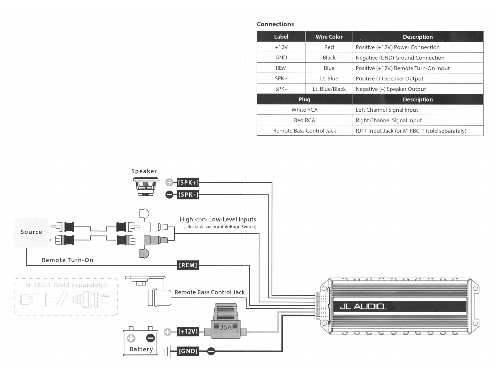
Connections
Source
Speaker
w
High
<or>
(selectable via
Low-Level Inputs
Input
Voltage Switch)
+12V
GND
REM
SPK+
SPK-
Remote
White
Red
Bass
Red
Black Negative (GND) Ground Connection
Blue Positive(+ 12V) Remote Turn-On
Lt
. Blue Positive(+) Speaker
Lt. Blue/Black
RCA
RCA
Control Jack
Positive(+ 12V) Power Connection
Output
Negative(-)
Left Channel Signal
Right Channel Signal
RJ
11
Input
Speaker
Jack for
Input
M-RBC-1
Input
Output
Input
(sold separately)
Remote
-------------
11
11
RBC 1
11
l ! -
- - - - - - - - - -
Turn-On
(Sod
Sepc1r
II
-~([Lf:
ltely
-·
_J
....
0 0
0 =
Battery
llMMI
Remote
I
11
Bass
Control Jack
 Loading...