

Page 1
OWNER’S MANUAL
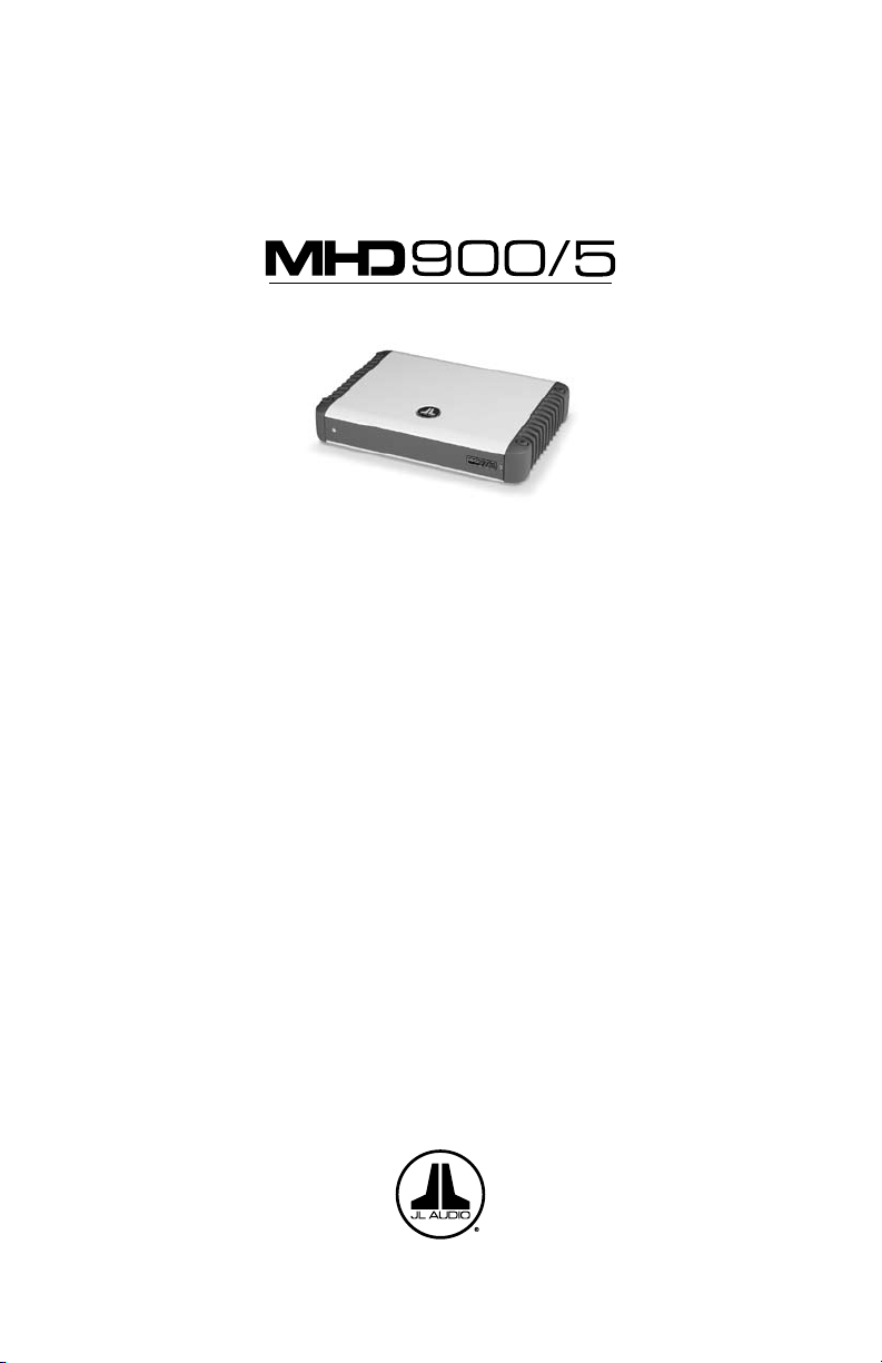
5-Channel Class-D Marine System Amplifier
Thank you for purchasing a JL Audio amplifier for
your marine sound system.
Your amplifier has been designed and manufactured to exacting
standards in order to ensure years of musical enjoyment in your vessel.
For maximum performance, we highly recommend that you have
your new amplifier installed by an authorized JL Audio dealer. Your
authorized dealer has the training, expertise and installation equipment
to ensure optimum performance from this product. Should you
decide to install the amplifier yourself, please take the time
to read this manual thoroughly so as to familiarize yourself
with its installation requirements and setup procedures.
If you have any questions regarding the instructions in this
manual or any aspect of your amplifier’s operation, please contact your
authorized JL Audio dealer for assistance. If you need further assistance,
please call the JL Audio Technical Support Department
at (954) 443-1100 during business hours.
Page 2
2 | JL Audio - MHD900/5 Owner’s Manual
3
PROTECT YOUR HEARING!
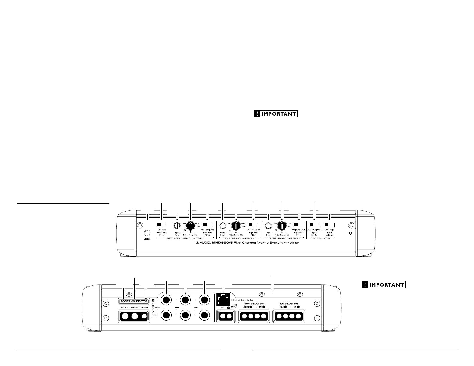
Filter Frequ ency
Selector
(pg. 11)
Filter Frequ ency
Selector
(pg. 10)
Input Voltage
Selection
(pg. 9)
Infrasonic Filte r
Selector
(pg. 11)
Input Sensiti vity
Contro l
(pg. 10)
Input Mode
Selection
(pg. 9)
Filter Slope
Selection
(pg. 11)
Filter Frequ ency
Selector
(pg. 11)
Input Sensiti vity
Contro l
(pg. 10)
Filter Slope
Selection
(pg. 11)
Input Sensiti vity
Contro l
(pg. 10)
Power Sta tus
Indicator
(pg. 15)
Filter Slope
Selection
(pg. 11)
Left & Right
Input Jacks:
Subwoofer
(pg. 9)
Left & Right
Input Jacks:
Front Channels
(pg. 9)
Speaker Outputs
(pgs. 13-14)
Jack for
Remote Lev el
Control K nob
(pg. 13)
Left & Right
Input Jacks:
Rear Channels
(pg. 9)
Chassis Ground
Connector
(pgs. 6-7)
Remote Turn-On
Connector
(pgs. 6-7)
+12 V Power
Connector
(pgs. 6-7)
We value you as a long-term customer. For
that reason, we urge you to practice restraint in
the operation of this product so as not to damage
your hearing and that of others in your vessel.
Studies have shown that continuous exposure to
high sound pressure levels can lead to permanent
(irreparable) hearing loss. This and all other
high-power amplifiers are capable of producing
such high sound pressure levels when connected
to a speaker system. Please limit your continuous
exposure to high volume levels.
While driving, operate your audio system in
a manner that still allows you to hear necessary
noises to operate your vessel safely (horns,
sirens, etc.).
SERIAL NUMBER
In the event that your amplifier requires
service or is ever stolen, you will need to have
a record of the product’s serial number. Please
take the time to enter that number in the space
provided below. The serial number can be found
on the bottom panel of the amplifier and on the
amplifier packaging.
Serial Number:
INSTALLATION APPLICATIONS
This amplifier is designed for operation in
vessels with 12 volt, negative-ground electrical
systems. Use of this product in vessels with
positive ground and/or voltages other than 12V
may result in damage to the product and will void
th e w ar ran ty.
This product is not certified or approved for
use in aircraft.
Do not attempt to “bridge” the outputs of this
amplifier with the outputs of a second amplifier,
including an identical one.
PLANNING YOUR INSTALLATION
It is important that you take the time to read
this manual and that you plan out your
installation carefully. The following are some
considerations that you must take into account
when planning your installation.
Cooling Efficiency Considerations:
The outer shell of your JL Audio amplifier
is designed to remove heat from the amplifier
circuitry. For optimum cooling performance,
this outer shell should be exposed to as large a
volume of air as possible. Enclosing the amplifier
in a small, poorly ventilated chamber can
lead to excessive heat build-up and degraded
performance. If an installation calls for an
enclosure around the amplifier, we recommend
that this enclosure be ventilated with the aid
of a fan. In normal applications, fan-cooling
is not necessary.
Mounting the amplifier upside down is
strongly discouraged.
If mounting the amplifier under a seat,
make sure there is at least 1 inch (2.5 cm) of
space above the amplifier’s outer shell to permit
proper cooling.
Safety Considerations:
Your amplifier needs to be installed in a dry,
well-ventilated environment and in a manner
which does not interfere with your vessel’s factory
installed electronic devices. You should also take
the time to securely mount the amplifier so that
it does not come loose in the event of a collision/
sudden jolt or as a result of the repeated vibrations
the vessel is prone to during normal operation.
Stupid Mistakes to Avoid:
• Check before drilling any holes in your vessel to
make sure that you will not be drilling through
the hull, a fuel tank, fuel line, wiring harness or
other vital vessel system.
• Do not run system wiring outside or underneath
the vessel. This is an extremely dangerous
practice which can result in severe damage to
your vessel and person.
• Protect all system wires from sharp edges
(metal, fiberglass, etc.) by carefully routing
them, tying them down and using grommets
and loom where appropriate.
• Do not mount the amplifier in the engine
compartment or in any other area that will
expose the amplifier circuitry to the elements.
While this amplifier is specially designed
for marine applications, it is not waterproof
and it should not be mounted where it is likely
to get wet.
Page 3

4 | JL Audio - MHD900/5 Owner’s Manual
5
PRODUCT DESCRIPTION
The JL Audio MHD900/5 is a very powerful
and compact five-channel amplifier utilizing
patented Single Cycle Control ™ Class D
technology for all channels. This groundbreaking
technology delivers reference-grade, fullrange sonic performance while requiring
far less current from the vessel’s electrical
system than a conventional amplifier.
JL Audio’s exclusive R.I.P.S. power supply
design optimizes the output of each channel
section for any impedance between 1.5 and 4
ohms per channel (3-8 ohms bridged on front
and rear sections) allowing you to get full use of
the MHD900/5’s performance capabilities with a
wide range of speaker systems.
The tightly regulated power supply design also
means that the MHD900/5’s clean power output
capability remains stable over a wide range of
vessel voltages, resulting in enhanced fidelity.
The MHD900/5 flexible, studio-grade signal
processing allows it to be deployed in several
different system configurations:
1) As a five-channel amplifier in a bi-amplified
system, driving four satellite speakers (100W x
4), plus a subwoofer system (500W x 1).
2) As a very powerful three-channel amplifier
in a bi-amplified system, driving t wo satellite
speakers (150W x 2, bridged), plus a subwoofer
system (500W x 1).
3) As a five-channel amplifier in a tri-amplified
system, driving two tweeters (100W x 2), plus
two woofer/mids (100W x 2), plus a subwoofer
system (500W x 1). An external 2-way
crossover is required for this application.
The MHD900/5’s flexible input and
crossover sections permit operation with
a wide variety of source units and system
configurations. It can be operated with a single
pair of stereo inputs, with two pairs of stereo
inputs (front and rear) or with separate inputs
for its front, rear and subwoofer channels.
As we said, it’s very flexible.
TYPICAL INSTALLATION SEQUENCE
The following represents the sequence for
a typical amplifier installation, using an
aftermarket source unit or OEM Interface
processor (like the CleanSweep® CL441dsp).
Additional steps and different procedures may
be required in some applications. If you have
any questions, please contact your authorized
JL Audio dealer for assistance.
1) Disconnect the negative battery post
connection and secure the disconnected cable
to prevent accidental re-connection during
installation. This step is not optional!
2) Run positive and negative power wire
from the battery location to the amplifier
mounting location, taking care to route it
in such a way that it will not be damaged
and will not interfere with vessel operation.
4 AWG is the minimum recommended
wire size for this amplifier. Use a 2 AWG
or 1/0 AWG main power wire with a power
distribution block when additional amplifiers
are being installed with the MHD900/5 and
powered from the same main power wire.
3) Connect power wire to the positive battery
post. Fuse the wire with an appropriate fuse
block (and connectors) within 18 inches (45
cm) wire length of the positive battery post.
This fuse is essential to protect the vessel.
Do not install the fuse until the power wire
has been connected to the amplifier.
4) Connect negative power wire to the negative
battery post. Use the same size power wire as
the wire connected to the “+12 V” connection.
5) Run signal cables (RCA cables) and remote
turn-on wire from the source unit or interface
processor to the amplifier mounting location.
6) Run speaker wire from the speaker systems to
the amplifier mounting location.
7) Securely mount the amplifier using
appropriate hardware. (See page 8 for detailed
mounting instructions).
8) Connect the remote turn-on wire and the
positive and negative power wires to the
amplifier’s power connector plug. Then insert
the power connector plug into the amplifier’s
power connector receptacle, pushing firmly.
9) Connect the RCA input cables
to the amplif ier.
10) Connect the speaker wires to the speaker
connector plugs and insert the plugs firmly
into the speaker connector receptacles.
11) Carefully review the amplifier’s control
settings to make sure that they are set
according to the needs of the system.
12) Install power wire fuse (60A for a
single MHD900/5) and reconnect the negative
battery post terminal.
13) Turn on the source unit at a low level
to double-check that the amplifier is
configured correctly. Resist the temptation
to crank it up until you have verified the
control settings.
14) Make necessary adjustments to the input
sensitivity controls to obtain the right
overall output and the desired balance
in the system. See Appendix C (pages 18, 19)
for the recommended input sensitivity
setting method.
15) Enjoy the fruits of your labor with your
favorite music.
Page 4
6 | JL Audio - MHD900/5 Owner’s Manual
7
POWER AND TURNON CONNECTIONS
Before installing the amplifier, disconnect the
negative (ground) wire from the vessel’s battery.
This will prevent accidental damage to the system,
the vessel and your body during installation.
+12V Battery Connection
You will need to connect a power wire to
the vessel’s positive battery terminal, using an
appropriate power ring or specialized battery
terminal connector, such as the JL Audio
XB-BTU. This connection must be tight and
corrosion-free to ensure proper connectivity. This
wire MUST be fused appropriately for safety. Any
positive power wires run through metal barriers
, must be protected with a high quality insulating
grommet to prevent damage to the insulation
of the wire. Failure to do so may result in a
dangerous short circuit.
Power Wire Requirements
The MHD900/5’s “+12 V DC ” and “Ground”
connections are designed to accept 4 AWG
power wire. 4 AWG pure copper wire is
the minimum recommended wire size for
this amplifier. Use of smaller gauge wire
(including cheap wire that is fraudulently sold
as 4 AWG wire) can create a fire hazard.
If you are installing the MHD900/5 with other
amplifiers and wish to use a single main power
wire, use 2 AWG or 1/0 AWG pure copper wire
as a main power wire. This 2 AWG or 1/0 AWG
power wire should terminate into a distribution
block mounted as close to the amplifiers as
possible and should connect to the MHD900/5
with 4 AWG pure copper power wire, with
each smaller wire fused appropriately for each
amplifier or other electronics in the system.
Please note that lower AWG numbers mean
bigger wire and vice-versa (1/0 AWG is the largest,
2 AWG is smaller, then 4 AWG, then 8 AWG, etc.).
We do not recommend the use of “copper-clad
aluminum wire” or “CCA” wire because this
wire is significantly less conductive than pure
copper wire. Only use pure copper power wire,
such as JL Audio’s MetaWire™. Tinned copper
wire (silver color) is acceptable as the tin-plating
is only a very minor component of the wire.
Fuse Requirements
The installation of a fuse on the main power
wire, within 18 wire inches (45 cm) of the positive
battery terminal is vital to protect the wire and
the vessel from fire in the event of a collision
or short-circuit. The fuse value at each power
wire should be just high enough for all of the
equipment being run from that power wire. Do
not use a fuse with a value that far exceeds the
total fuse rating of the electronics connected to
the wire.
If only the MHD900/5 is being run from
a single power wire, install a 60A fuse to
protect the wire: AGU (big glass fuse). AFS
(small blade fuse) or MaxiFuse™ (big plastic-
body fuse) types are recommended.
If other amplifiers are also being powered from
a main power wire and exceed 80 amps in total
fuse rating, we recommend the use of an ANL
(large-blade) fuse and holder. Each amplifier can
then be fused independently at the outputs of
the power distribution block. Use JL Audio part
XC-FOA-2PAK and appropriate MaxiFuse™ type
fuses with JL Audio distribution blocks.
Please consult with your JL Audio
dealer to make sure that the wire, fuse
holder and fuse ratings are appropriate
for your system’s needs. The safety of
your installation depends on appropriate
power connections and fuse protection.
Ground Connection
The ground connection should be made using
the same gauge wire as the power connection.
It is common for the alternator to be grounded
through its chassis. If the alternator is not
grounded through its chassis and instead employs
a small (10 AWG - 6 AWG) wire to connect to
ground, this wire should also be upgraded to 4
AWG when installing amplifier systems with main
fuse ratings above 60A.
Many vessels employ small (10 AWG - 6 AWG)
wire to ground the batter y to the vessel chassis
and to connect the alternator’s positive
connection to the battery. To prevent voltage
drops, these wires should be upgraded to 4
AWG pure copper wire when installing amplifier
systems with main fuse ratings above 60A.
Turn-On Wire
The MHD900/5 uses a conventional +12V
remote turn-on wire, typically controlled by
the source unit’s remote turn-on output. The
amplifier will turn on when +12V is present at
its “Remote” input and turn off when +12V is
switched off. If a source unit does not have a
dedicated remote turn-on output, the amplifier’s
turn-on lead can be connected to +12V via a
switch that derives power from an ignitionswitched circuit.
The MHD900/5’s “Remote” turn-on connector
is designed to accept 18 AWG – 12 AWG wire. 18
AWG is more than adequate for this purpose.
To connect the remote turn-on wire to the
amplifier, first back out the set screw on the
bottom of the Power Connector Plug, using the
supplied hex wrench. Strip 1/2 inch (12mm) of
wire and insert the bare wire into the receptacle,
seating it firmly so that no bare wire is exposed.
When using smaller wire, it may be necessary to
strip 1 inch of insulation from the wire and fold
the bare wire in half prior to insertion. While
holding the wire in the terminal, tighten the
set screw firmly using the supplied 2.5 mm hex
wrench, taking care not to strip the head of the
screw and making sure that the wire is firmly
gripped by the set screw.
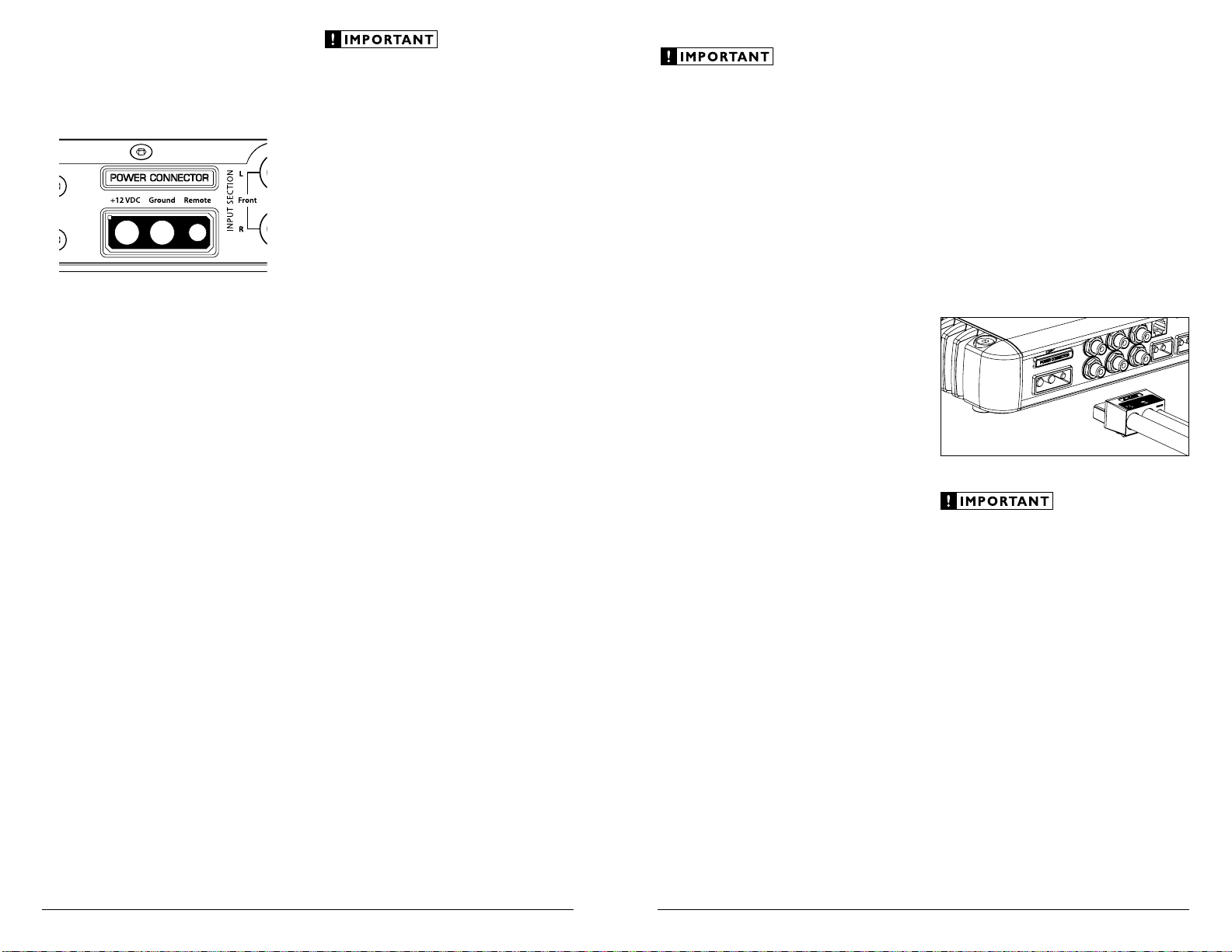
Amplifier Power Connector Plug
To connect the power wires and the remote
turn-on wire to the amplifier, unplug the power
connector plug from the amplifier chassis (pull
back firmly) and back out the set screws on
the connector plug, using the supplied 4 mm
hex wrench for the +12 V DC ” and “Ground”
connections and the supplied 2.5 mm hex wrench
for the “Remote” connection. Strip 3/8 inch (10
mm) of insulation from the end of each wire and
insert the bare wire into the receptacle on power
connector plug, seating it firmly so that no bare
wire is exposed. While holding each wire in place,
tighten each set screw firmly, taking care not to
strip the head of the screw.
Never make power connections with a “live”
wire. Always disconnect the negative battery
post before making any connections or
adjustments to a 12V power connection!
Page 5
8 | JL Audio - MHD900/5 Owner’s Manual
9
AMPLIFIER MOUNTING OPTIONS
The MHD900/5 has two mounting options to
ease in installation.
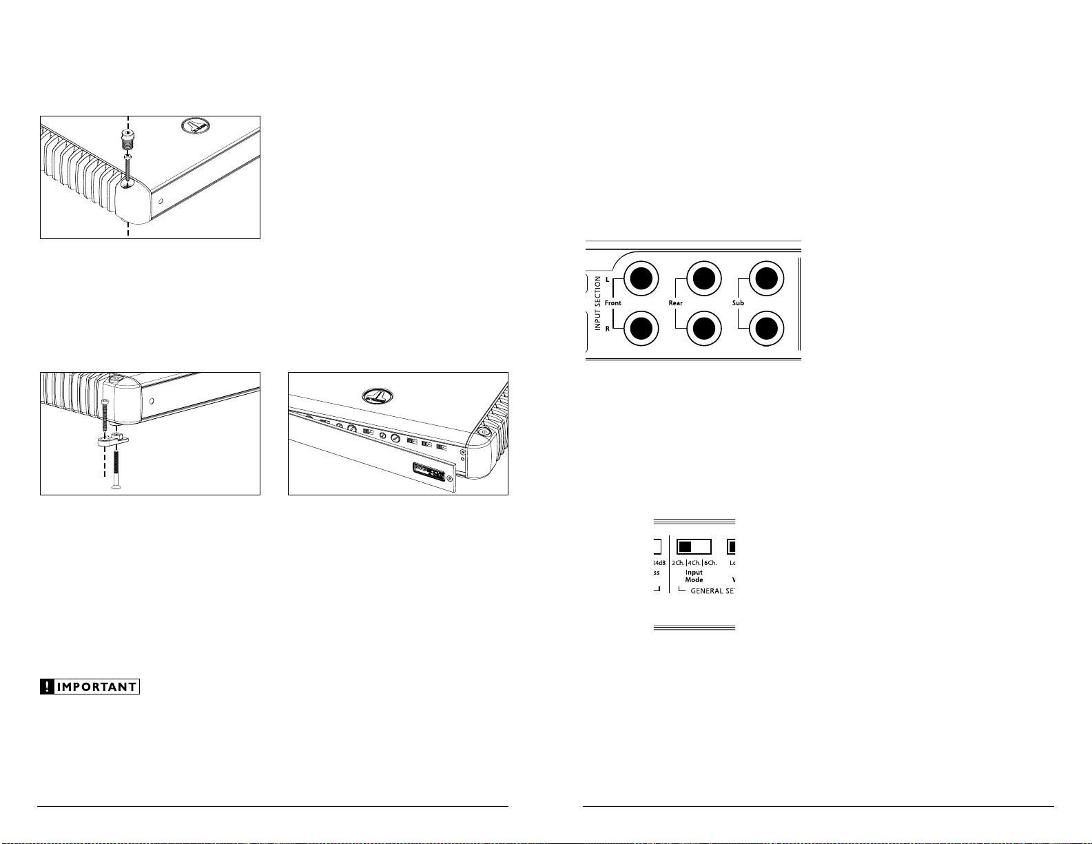
Standard Mounting
The standard method of mounting requires
removal of the four corner caps with the 4 mm
hex wrench included with your amplifier. Using
appropriate mounting screws (not included),
secure the amplifier in all four corners and
replace the corner caps to cover the screws.
Lateral Mounting Feet
Lateral Mounting Feet are also included
with your MHD900/5 to provide an alternative
mounting option. Each mounting foot
should be attached to the bottom of the
amplifier by screwing the provided bolt into
the bottom of the amplifier and up into the
corner cap with the supplied 2.5 mm hex
wrench. Next, using appropriate mounting
screws (not included), secure the amplifier
by its four Lateral Mounting Feet.
Check before drilling any holes in your vessel to
make sure that you will not be drilling through
a gas tank, brake line, wiring harness or other
vital vessel system.
CONTROL PANEL SECURIT Y COVER
The MHD900/5 features a Control Panel
Security Cover. When installed, the cover ensures
that your amplifier settings are not accidentally
changed while creating a clean aesthetic for the
amplifier and your installation. The control panel
security cover is pre-installed at the factory and
must be temporarily removed for access to the
controls described throughout this manual.
The security cover is secured by a single 2.5
mm hex-head screw at the far right of the panel.
Loosen the hex-head screw to release the security
cover (it is not necessary to completely remove the
screw). To re-install the security cover once all
adjustments have been made, insert the tongue on
the cover’s left edge into the groove where the leftside heatsink meets the control panel, hinge the
panel closed and secure the screw using the
supplied 2.5 mm hex wrench. Do not overtighten
the screw.
AMPLIFIER INPUTS
The MHD900/5 has three separate input
sections, one for the “Front” left and right
channels, another for the “Rear” left and
right channels and one for the Subwoofer
Channel. Each section consists of a pair of
RCA-type input jacks on the Connection
Panel of the amplifier and input controls on
the Control Panel of the amplif ier: a single
“Input Voltage” switch, an “Input Mode”
switch and three individual “Input Sens.”
rotary controls (one in each channel section).
“INPUT MODE” SWITCH
The “Input Mode” switch is located under
the “General Setup” heading at the far right of
the control panel. This switch allows operation
of all five amplif ier channels with only one pair
of input signals (2 ch.) or with independent front
and rear input signal pairs (4 ch.) or with discrete
front, rear and subwoofer signal pairs (6 ch.).
“6 Ch.” Input Mode
In this mode, you will connect separate pairs
of input cables to the “Front”, “Rear” and “Sub”
amplifier inputs, allowing you full channel
control from the source unit. If the source unit
only provides a mono (single) subwoofer output,
use a y-adaptor cable to feed both the “Left” and
“Right” subwoofer inputs of the MHD900/5 with
the mono signal. Failure to do so will result in
reduced gain and possible distortion.
“4 Ch.” Input Mode
In this mode, you will connect separate
pairs of input cables to the “Front” and “Rear”
amplifier inputs and leave the “Sub” inputs
unused. The subwoofer channels will receive
signal from the sum of the signals at the “Front”
and “Rear” inputs so that front-to-rear fading of
the main channels does not significantly affect
the subwoofer level.
“2 Ch.” Input Mode
To operate al l five chan nels of the M HD900/5
with a single pair of stereo inputs, select the
“2 Ch.” position on the “Input Mode ” switch
and connect a single pair of input cables to the
“Front” input jacks only. The “Rear” and “Sub”
input jack s will remain u nused. In t his mode, the
amplifier will route the signals connected to t he
“Front” inputs to the Front, Rear and Subwoofer
channels. Front-to-rear fading will not be available.
“Input Voltage” Switch
A wide range of signal input voltages can
be accommodated by each of the MHD900/5’s
differential-balanced inputs (200mV – 8V
RMS). This wide range is split up into two
sub-ranges, accessible v ia the “Input Voltage”
switch located next to the “Input Mode”
switch under t he “General Setup” heading.
The “Low ” position of the “Input Voltage”
switch selects an input sensitivity range between
200mV and 2V for all the amplif ier channels. This
means that the “Input Sens .” rotary controls will
operate within that voltage window. If you are
using an af termarket source un it, with prea mplevel outputs, this is most likely the position that
you will use (regardless of what voltage output
capability is claimed by the source unit).
The “High” position of the “Input Voltage”
switch selects an input sensitivity range between
800mV and 8V. This is for use with speaker-level
outputs from source units and small amplifiers
found in many OEM (factory-installed) systems.
To use speaker-level sources, splice the speaker
output wires of the source unit or small amplifier
onto a pair of RCA plugs for each input pair or use
the JL Audio ECS Speaker Wire to RCA adaptor
(XB- CLRAIC2-SW). It is not necessa ry (or
advisable) to use “Line Out put Converters” w ith
your MH D900/5.
Page 6
10 | JL Audio - MHD900/5 Owner’s Manual
11
The output of the amplifier decreases for a
given input voltage when the “Input Range”
switch is placed in the “High” position. The
output increases with the switch in the “Low”
position. While this may sound counterintuitive, it is correct as described.
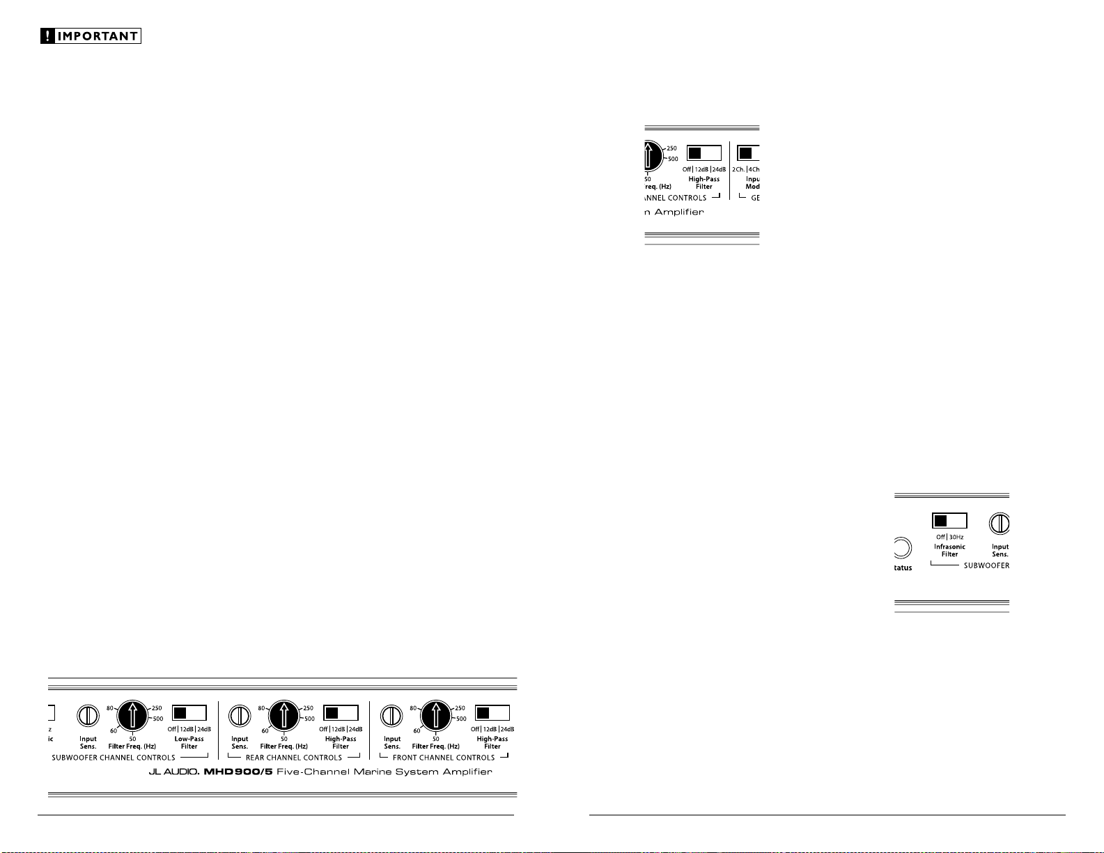
CHANNEL CONTROL SECTIONS
To the left of the “General Setup” section on
the Control Panel of the amplifer are three sets of
controls: one for the “Rear Channel Controls”
one for the “Front Channel Controls” and
one for the “Subwoofer Channel Controls”.
In each of these sections you will find a
rotary control labeled “Input Sens.” (Input
Sensitivity). These controls are designed to match
the input sensitivity of each channel section of
the MHD900/5 to the specific signal source that
is feeding the amplifier. These controls must be
adjusted, with care, following the procedures
outlined in this manual. Failure to make correct
adjustments can result in weak output, excessive
distortion and/or undesirable noise in the audio
output of the amplifier!
Note: The Channel Control sections also house
“High-Filter” or “Low-Pass Filter” and “Filter
Fre q.” controls. These are crossover filter controls
and will be discussed in the next section of this
manual. This section will explain the Input
Controls only.
“Input Sens.” Controls
Once the appropriate “Input Voltage” range
has been selected in the “General Setup” section
of the amplifier, the “Input Sens.” controls are
used to match the source unit’s output voltage to
the input stage of each pair of amplifier channels
for maximum clean output. Rotating the control
clockwise will result in higher sensitivity (louder
for a given input voltage). Rotating the control
counter-clockwise will result in lower sensitivity
(quieter for a given input voltage). To properly
set each pair of amplifier channels for maximum
clean output, please refer to Appendix C (pages
18, 19) in this manual.
After using this procedure, you can then adjust
the relative level of each channel pair by adjusting
the input sensitivity downward on any of the
channel sections, if they require attenuation to
achieve the desired system balance.
Do not increase the “Input Sens.” setting for
any amplifier or channel section in the system
beyond the maximum level established during
the procedure outlined in Appendix C (pages 18,
19). Doing so will result in audible distortion and
possible speaker damage.
Be aware that all three “Input Sens.”
adjustments will need to be made, regardless
of how many input cables are feeding the
amplifier. These controls will allow you to set
the appropriate relative levels for the “Front”
channels relative to the “Rear” channels and the
“Sub” channel (and any other amplifier channels
in the system).
CROSSOVER CONTROLS
Crossovers are groups of electronic filters
designed to control the frequency ranges
that each speaker in a system will be tasked
with reproducing. Proper crossover setup is
critical to sound quality and reliability.
The MHD900/5 has three individually
adjustable filter controls, one for the “Front”
channels, one for the “Rear” channels and
another for the “Sub” channel. The “Front”
and “Rear” filters are high-pass filters (they
attenuate low frequencies), while the “Sub”
channel filter is a low-pass filter (attenuates
high frequencies). For each filter, the user can
select from a shallow (12dB/octave) filter slope
Experiment to find the slope or combination
of slopes which best matches the acoustic
requirements of your system.
or a more aggressive (24dB/octave) slope.
2) “Filter Freq. (Hz)” Control:
This control selects the frequency at which the
filter begins to attenuate the signal and refers
specifically to the frequency at which output
has been attenuated by -3dB.
The filter frequency markings surrounding this
rotary control are for reference purposes and are
generally accurate to within 1/3 octave or better. If
1) “High-Pass Filter” Controls (Front and Rear
channels) or “Low-Pass Filter” Control (Sub
you would like to select the filter cutoff frequency
with a higher level of precision, consult the charts
in Appendix B (page 18) of this manua l.
Channel): These switches allow you to select filter
slopes or defeat the filter(s) completely.
“80 Hz” is a good starting point for most systems
where a subwoofer is connected to the Subwoofer
“Off”: Defeats the filter completely. Useful when
using an external crossover, such as one built into
Channel and component systems or coaxials to
the four main channels.
a head unit or signal processor.
“ 12dB”: Configures the filter to attenuate
frequencies above or below the selected
filter frequency at a rate of 12 dB per octave
(Butterworth alignment).
INFRASONIC FILTER Subwoofer Ch. Only)
The “Infrasonic Filter” is a 24 dB/octave high-
pass filter, with a fixed cutoff frequency of 30 Hz.
This filter is designed to conserve amplifier power
and protect subwoofer systems, without audibly
degrading the sub-bass output.
“ 24dB”: Configures the filter to attenuate
frequencies above or below the selected filter
frequency at a rate of 24 dB per octave (Linkwitz-
Riley alignment).
Depending on the speaker system and the
vessel, different filter slopes may be required to
produce a smooth transition between the sound
of different speakers in the system.
In high-pass mode, the sharper “24dB” setting
will do a better job of protecting small speakers
with limited power handling. In low-pass
mode, the “24dB” setting can also help by more
aggressively removing lower midrange output
from a subwoofer system.
The shallower “12dB” octave setting
allows for more output overlap between
the speakers being crossed over. In many
cases, this will result in a smoother “blend”
or transition between speaker systems.
With ported enclosures, the use of the
“Infrasonic Filter” is highly recommended to
protect the speaker(s) from excessive excursion
below box tuning.
With sealed enclosures, the use of the filter
is less necessary, but can still help protect the
speaker system from excessive excursion.
The “Infrasonic Filter” can be completely
defeated by selecting the “Off ” position on its
switch. This bypasses all signal from flowing
through the circuit.
Page 7
12 | JL Audio - MHD900/5 Owner’s Manual
13
BIAMPLIFIED SYSTEMS
Bi-amplified systems are defined as systems
in which separate amplifier channels drive lowfrequency (LF) and high-frequency (HF) speakers
and are separately filtered to send appropriate
frequency ranges to each speaker system.
The most common application of
bi-amplification in mobile audio is to drive a
subwoofer system from one or more amplifiers or
channels and component speakers from separate
amplifiers or channels.
The MHD900/5 can be easily configured to
drive a complete bi-amplified system consisting
of a subwoofer and four main speakers or a
subwoofer and two main speakers.
Bi-Amplified System with one MHD900/5
driving four main speakers plus subwoofer
(5-Channel Mode)
In this conf iguration, the “Front” channels
of the MHD900/5 will drive front component
speakers (stereo 100W x 2 @ 4Ω) with high-
pass filtering. The “Rear” channels will drive
rear component speakers in stereo (100W x 2
@ 4Ω) with high-pass filtering. The subwoofer
channel will drive the subwoofer system
(500W x 1 @ 1.5-4Ω) with low-pass filtering.
Once the input sections have been configured
appropriately, go to the “Front Channel
Controls” Section. Select “12dB” or “24dB” on
the “High-Pass Filter” and an appropriate “Filter
Freq.” (80-90 Hz is a good starting point).
Next, turn your attention to the “Rear
Channel Controls” Section and select “12dB”
or “24dB” “High-Pass Filter” switch and an
appropriate “Filter Freq.” (again, 80-90 Hz is a
good starting point).
Finally, in the “Subwoofer Channel
Controls” Section, select “12 dB” or
“24dB” on the “Low-Pass Filter” Switch
and a “Filter Freq.” of 80-90 Hz.
After proper adjustment of the
MH D9 00/ 5’s “Input Range” and “Input
Sens.” controls, you can fine tune filter
frequencies and slopes and attenuate each
channel section to achieve proper balance.
Bi-Amplified System with one MHD900/5
driving two main speakers plus subwoofer
(3-Chann el Mode)
In this conf iguration, the “Front” channels
of the MHD900/5 will be bridged to drive the
left front component speaker system (150W x
1 @ 4Ω) with high-pass filtering. The “Rear”
channels will be bridged to drive the right front
component speaker system (150W x 1 @ 4Ω),
also with high-pass filtering. The “Subwoofer”
channel will drive the subwoofer system
(500W x 1 @ 1.5-4Ω) with low-pass filtering.
For information on proper bridging
techniques refer to the section titled “Bridging
Considerations” in this manual (page 14).
Once the input sections have been configured
appropriately, go to the “Front Channel
Controls” Section. Select “12dB” or “24dB”
on the “High-Pass Filter” and an appropriate
“Filter Freq.” (80-90 Hz is a good starting point).
Next, turn your attention to the “Rear
Channel Controls” section and set it exactly the
same as you set the “Front Channel Controls”.
Finally, in the “Subwoofer Channel
Controls” section, select “12dB ” or
“24dB” on the “Low-Pass Filter” switch
and a “Filter Freq.” of 80-90 Hz.
After proper adjustment of the MHD900/5’s
“Input Range” and “Input Sens.” controls,
you can fine tune filter frequencies and
slopes and attenuate each channel section to
achieve proper balance. Keep in mind that
the left and right front speakers will have
independent “Input Sens.” controls in this
configuration, and these need to be carefully
matched for proper stereo performance.
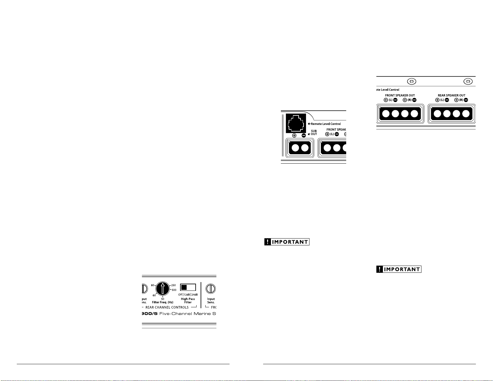
REMOTE LEVEL CONTROL OPTIONAL
With the addition of the optional Remote Level
Control (HD-RLC), you can control the level of
the Subwoofer Channel of the MHD900/5 from
the front of the vessel. The HD-RLC connects
to the jack labeled “Remote Level Control” on
the Connection Panel of the amplifier using
a standard telephone cable (supplied with the
HD-RLC).
If desired, multiple MHD amplifiers can be
controlled from a single HD-RLC controller
using a simple phone line “splitter”
and multiple phone cables.
When connected to the amplifier, the HD-RLC
operates as follows. At full counter-clockwise
rotation, the audio will mute completely. At full
clockwise rotation the level will be the same as if
the HD-RLC was not connected at all. In other
words, it operates strictly as a level attenuator.
When no HD-RLC is connected, the Level
Control circuit is defeated.
The RBC-1 Remote Bass Control used with
JL Audio Slash, Slash v2, e-Series, A-Series and
G-Series amplifiers is NOT compatible with the
HD/MHD Series amplifiers. If you attempt to
connect an RBC-1 to an HD amplifer, the
control will not work. You must use the
HD-RLC controller.
SPEAKER OUTPUTS
The MHD900/5 employs JL Audio’s exclusive
Regulated, Intelligent Power Supply (R.I.P.S.)
design. The operation of the R.I.P.S. system is
independent for each channel section. This
sophisticated power supply allows the amplifier to
produce its optimum power into higher
impedances as well as low impedances.
The R.I.P.S.-equipped MHD900/5 gives
you the freedom to use a variet y of speaker
configurations that achieve final nominal
impedances between 1.5 – 4Ω per channel
in stereo while maintaining 75 - 100W x 4
of clean power output. When bridged, each
main channel pair will optimize output at
150-200 watts between 3 – 8Ω. The mono
subwoofer channel will deliver its full 500W
output into any impedance between 1.5-4Ω.
The operation of the R.I.P.S. circuitry is
entirely automatic and adjusts itself every time the
amplifier is turned on. There are no user controls
to configure. The system operates through
multiple stages of impedance optimization,
choosing the stage most appropriate to the actual
impedance of the speakers you connect to it.
If you connect a load higher than 4Ω nominal
per channel in stereo mode (or 8Ω in bridged
mode), power will drop by half with every
doubling of impedance above 4Ω stereo / 8Ω
mono. If you connect a load lower than 1.5Ω
nominal per channel in stereo mode (or 3Ω in
bridged mode, the amplifier protection
circuitry activates a “safe” mode which reduces
amplifier power to protect the circuitry from
failure (the LED status indicator on the control
panel will light up amber to indicate that this
has happened). See page 15 for details.
Page 8
14 | JL Audio - MHD900/5 Owner’s Manual
15
BRIDGING CONSIDERATIONS
Bridging is the practice of combining the output
of two amplifier channels to drive a single load.
When bridged, each channel produces signals
of equal magnitude, but opposite polarity. The
combined output of the two channels provides
twice the output voltage available from a single
channel. The MHD900/5 has been designed for
bridging of its two main channel pairs without the
need for input inversion adaptors.
The mono subwoofer channel cannot be
bridged to another mono channel.
To bridge either pair of main channels, use the
“Left +” and “Right –” speaker connectors only
(th e “Left –” and “Right +” remain unused).
Then connect a mono signal to both left
and right RCA inputs for that channel pair.
This requires an RCA “Y-Adaptor” (sold
separately), because a bridged pair of channels
requires that both amplifier channels of the
bridged pair receive input. Connection of
only one RCA input will result in reduced
power output, increased distortion and
can cause the amplifier to overheat.
When bridged, each channel pair will
deliver optimum power into a 3-8Ω load.
Operating bridged channel pairs into a load
lower than 3Ω is not recommended.
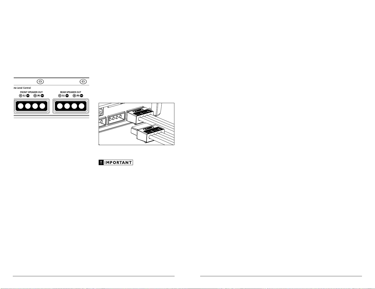
Speaker Connector Plugs
There are three speaker connector
plugs on the MHD900/5: one for the
front channels, one for the rear channels
and one for the subwoofer channel.
To connect the speaker wires to the amplifier,
unplug the speaker connector plugs from the
amplifier chassis (pull back firmly) and back out
the set screws on each connector plug, using the
supplied 2.5 mm hex wrench. Strip 3/8 inch (10
mm) of insulation from the end of each wire and
insert the bare wire into the receptacle on the
speaker connector plug, seating it firmly so that
no bare wire is exposed. While holding each wire
in place, tighten each set screw firmly, taking care
not to strip the head of the screw.
Speaker loads below 1.5Ω nominal per channel
in stereo or 3Ω nominal in bridged mode are
not recommended and may cause the amplifier
output to distort excessively.
“STATUS” LED / PROTECTION CIRCUITRY
There is a single multi-color LED on the
control panel of the amplifier to indicate the
amplifier’s operating status. This LED’s behavior
is as follows:
1) Flashing Green: amplifier is powering up,
audio output is muted.
2) Constant Green: amplifier is on and
functioning normally, audio output is active.
3) Constant Red: lights to indicate that the
amplifier has exceeded its safe operating
temperature, putting the amplifier into a selfprotection mode, which temporarily reduces
the peak power output of the amplifier. The
red light will turn green and the amplifier will
return to full-power operating mode when its
temperature returns to a safe level.
3) Constant Amber (yellow): lights to indicate
that at least one channel is in overcurrent
protection mode. This could mean that the
impedance of the speaker load connected to
the amplifier is lower than the optimum load
impedance range for the amplifier. When this
light is on, a protection circuit engages and
reduces the power output of the channel(s)
experiencing the problem. This can manifest
itself as audible distortion.
The amber indicator will also light when
a short-circuit is detected in the speaker
wiring (this can be a short between the
positive and negative spea ker wires or
between either speaker wire and the vessel
chassis). This can be used to diagnose a
short-circuit by only connecting one of the
amplifier sections at a time (“Front” or
“Rear” or “Sub” channels). The amber LED
will light when you connect the section that
is experiencing the problem and turn the
volume up. Note that a short in the speaker
wiring may show an alternating red/green
status light with no signal (volume down).
4) Alternating Red and Green: lights to indicate
that the amplifier is experiencing a fault that
may require service of the amplifier, its wiring
or the vessel’s charging system. Audio is muted
when this fault occurs. The most likely cause
of this fault is a low supply voltage condition.
If battery voltage drops below 8.5 volts at any
point, the amplifier (except for the “Status”
LED) will shut itself off to protect itself and the
vessel’s charging system. If the Remote TurnOn voltage drops below 6 volts, the “Status”
LED will also turn off.
The amplifier will turn back on automatically
when voltage climbs back above 9 volts. This
shut-down and turn-on behavior may happen
in a rapid cycle when bass-heavy program
material causes a weak charging system to
momentarily dip too low. If this is happening
in your system, have your charging system
inspected to make sure it is working properly.
If no problem is found with the supply voltage
to the amplif ier and you are still seeing
alternating Red and Green on the “Status”
LED, check that there are no short-circuits to
chassis ground in any of the speaker wiring
in the vessel. Disconnect speaker connectors
from the amplifier one-by-one to check.
If no problem is found with the supply or
remote voltage, disconnect everything except
power/ground/remote. If the amplifier is then
turned on and displays an alternating redgreen, the amplifier needs service.
For more information on troubleshooting this
amplifier, refer to Appendix D (pages 20, 21).
Page 9

16 | JL Audio - MHD900/5 Owner’s Manual
17
SERVICING YOUR JL AUDIO AMPLIFIER
If your amplifier fails or malfunctions, please
return it to your authorized JL Audio dealer so
that it may be sent in to JL Audio for service.
There are no user serviceable parts or fuses inside
the amplifier. The unique nature of the circuitry
in the JL Audio amplifiers requires specifically
trained service personnel. Do not attempt
to service the amplifier yourself or through
unauthorized repair facilities. This will not only
void the warranty, but may result in the creation
of more problems within the amplifier.
If you have any questions about the installation or
setup of the amplifier not covered in this manual,
please contact your dealer or technical support.
JL Audio Technical Support:
(9 5 4 ) 4 4 3 -11 0 0
9:00 AM – 5:30 PM (Eastern Time Zone)
Monday - Friday
APPENDIX A:
MHD900/5 Specifications
Amplifier Topology: Class D, switching type with
patented Single-Cycle Control™ technology.
Power Supply: Pulse width modulation-regulated
switching power supply
Recommended Fuse Value / Type: 60A (AFS, AGU or
Max iFuse™)
Rated Power (Main Channels / Stereo):
100W RMS x 4 @ 4Ω (11V - 14.5V)
75W RMS x 4 @ 1.5-3Ω (11V - 14.5V)
Rated Power (Main Channels / Bridged):
200W RMS x 2 @ 8Ω (11V - 14.5V)
150W RMS x 2 @ 3- 6Ω (11V - 14.5V)
Rated Power (Subwoofer Channel):
500W RMS x 1 @ 1.5-4Ω (11V - 14.5V)
THD at Rated Power:
Main Channels: <0.03% @ 4Ω per channel
Subwoofer Channel: <0.05% @ 4Ω
(Average at 1 kHz)
Signal to Noise Ratio (20 kHz Bandwidth):
Referred to Rated Power: 108 dBA
Referred to 1 Watt: 8 8 dBA
Frequency Response (Main Channels):
12 Hz - 28 kHz (+0, -1dB)
Frequency Response (Subwoofer Channel):
12 Hz - 10 kHz (+0, -1dB)
Damping Factor (Main Channels):
>400 @ 4Ω per ch. / 50 Hz
>200 @ 2Ω per ch. / 50 Hz
Damping Factor (Subwoofer Channel):
>800 @ 4Ω / 50 Hz
>400 @ 2Ω / 50 Hz
Crossover Filters:
High-Pass Filters: Front Channels and Rear Channels
Low-Pass Filter: Subwoofer Channel
Filter Type (all channels): 12 dB/octave Butterworth or
24 dB/octave Linkwitz-Riley
Cutoff Freq. Range: Continuously variable, 50 - 500 Hz
Input Sections:
No. of Inputs: Three Stereo Pairs (Front, Rear and Sub)
Input Type: Differential-balanced with RCA jack inputs
Input Range: Switchable from 200mV - 2V RMS (Low)
to 800mV - 8V RMS (High)
Chassis Dimensions (LxWxH):
Due to ongoing product development, all specifications are subject to
change without notice.
10.74 in. x 7.85 in. x 1.93 in. (273 mm x 199.5 mm x 49 mm)
Dimensions do not include connectors.
Page 10
18 | JL Audio - MHD900/5 Owner’s Manual
19
APPENDIX B:
Precise Frequency Selection Chart
“FILTER FREQ”
Detent Panel Actual
Number Marking Freq. (Hz)
Full counter-clockwise: 53
01 ...........“50” ............53
02 ............................53
03 ............................53
04 ............................53
05 ............................54
06 ............................55
07 ............................57
08 ............................58
09 ...........“60” ............60
10 ............................62
11 ............................64
12 ............................66
13 ............................69
14 ............................71
15 ............................74
16 ............................77
17 ...........“80” ............80
18 ............................85
19 ............................86
20 .............. ..............90
21 ............................95
22 ...........................100
23 ...........................104
24 .............. .............110
25 .......“12 o’clock” .......116
26 ...........................123
27 ...........................131
28 ...........................141
29 ...........................151
30 ...........................165
31 ...........................180
32 ...........................200
33 ...........................224
34 ..........“250” ..........248
35 ...........................293
36 ...........................347
37 ...........................422
38 ...........................459
39 ..........“500” ..........504
40 ...........................508
41 ...........................508
Full-clockwise: 508
APPENDIX C:
Input Sensitivity Level Setting
JL Audio amplifiers utilizing the Regulated
Intelligent Power Supply (R.I.P.S.) allow
delivery of their rated power when connected
to any load impedance from 1.5 - 4Ω per
channel and when connected to a charging
system with any voltage from 11 - 14.5V.
This design is beneficial for many reasons.
One of these reasons is ease of setup.
Because each JL Audio amplifier will always
deliver the same amount of power within
its operational range of supply voltages, the
maximum, unclipped output is very predictable.
This makes setting the gain structure via the
input sensitivity controls very simple. Following
the directions below will allow the user to adjust
the input sensitivity of the amplifier(s) simply
and easily in just a few minutes using equipment
which is commonly available in installation bays.
Necessary Equipment
• Digital AC Voltmeter
• CD with a sine-wave test tone recorded at
0 dB reference level in the frequency range
to be amplified for that set of channels
(50 Hz for subwoofer channels, 1 kHz for
a midrange application). The CleanSweep®
Calibration Disc contains the appropriate
test tones and is available for sale at
http://store.jlaudio.com Do not use attenuated
test tones (-10 dB, -20 dB, etc.).
Do not increase any “Input Sens.” setting in
the system beyond the maximum level
established during this procedure. Doing so
will result in audible distortion and possible
speaker damage.
It will be necessary to re-adjust the “Input
Sens.” for the affected channels if any equalizer
boost is activated after setting the “Input
Sens.” with this procedure. This applies to any
EQ boost circuit, source unit tone controls or EQ
circuits. EQ cuts will not require re-adjustment.
The Nine-Step Procedure
(follow this procedure for each pair of channels)
1) Disconnect the Spea ker Connector Plugs.
2) Turn off all processing on the source unit
(bass/treble, loudness, EQ, etc.). Set fader
control to center position and subwoofer
level control to 3/4 of maximum (if used
to drive the MHD900/5). Disconnect
the HD-RLC Remote Level Control
temporarily (if one is being used).
3) Switch the “Input Voltage” to “Low” and
turn the “Input Sens.” control on both sets of
channels all the way down.
4) Set the source unit volume to 3/4 of full
volume. If the subwoofer channel is being
driven by a source unit’s dedicated subwoofer
output, also adjust the source unit’s subwoofer
level control to 3/4 of maximum output. This
will allow for reasonable gain overlap with
moderate clipping at full volume.
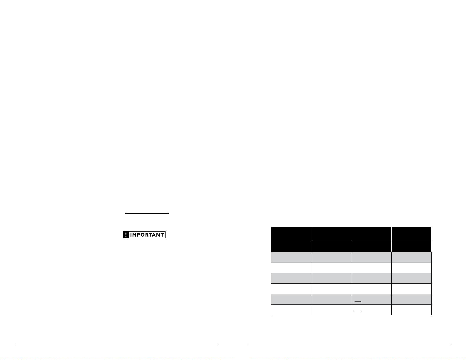
5) Using the chart below, determine the
target voltage for input sensitivity
adjustment according to the nominal
impedance of the speaker system
connected to each set of outputs.
6) Verify that you have disconnected the Speaker
Connector Plugs before proceeding. Play a
track with an appropriate sine wave (within the
frequency range to be amplified by each set of
channels) at 3/4 source unit volume.
FRONT OR REAR
Nom.
Impedance
Stereo Bridged Mono
8 20.0 V 40.0 V 44.7 V
6 20.0 V 32.0 V 44.7 V
4 20.0 V 24.6 V 44.7 V
3 16.0 V 21.2 V 38.7 V
2 12.3 V
1.5 10.6 V
7) Connect the AC voltmeter to the “Front
Speaker Outputs” or “Rear Speaker Outputs”
connectors of the amplifier. If the channel pair
is operating in stereo, it is only necessary to
measure one channel in the pair. If bridged,
make sure you test the voltage at the correct
connectors (L+ and R–).
8) Increase the “Input Sens.” control until
the target voltage is delivered for that
set of channels. If excessive voltage is
read with the control at minimum (full
counterclockwise), switch the “Input
Vol ta ge ” switch to “High” and re-adjust.
9) Once you have adjusted each set of channels to
its maximum unclipped output level, reconnect
the speaker(s). The “Input Sens.” controls can
now be adjusted downward any set of channels
requires attenuation to achieve the desired
system balance.
SUBWOOFER
CHANNELS
not recommended
not recommended
CHANNEL
31.6 V
27.4 V
Page 11

20 | JL Audio - MHD900/5 Owner’s Manual
21
APPENDIX D: TROUBLESHOOTING
“How do I properly set the input sensitivity on my amplifier”
Please refer to Appendix C (pages 18, 19) to set the input sensitivity
for maximum, low-distortion output.
“My amplifier doesn’t turn on”
Check the fuse(s), not just visually, but with a continuity meter. It
is possible for a fuse to have poor internal connections that
cannot be found by visual inspection. It is best to take the
fuse out of the holder for testing. If no problem is found with
the fuse, inspect the fuse-holder.
Check the integrity of the connections made to each of the
“+12V DC ”, “Ground”, and “Remote” terminals. Ensure
that no wire insulation is pinched by the terminal set screw
and that each connection is tight.
Check to make sure there is +12V at the “Remote” connection of the
amplifier. In some cases, the turn-on lead from the source unit
is insufficient to turn on multiple devices and the use of a relay
is required. To test for this problem, jump the “+12V DC ” wire
to the “Remote” terminal to see if the amplifier turns on.
“I get a distorted / attenuated sound coming out of the speaker(s)”
Check the speaker wires for a possible short, either between the
positive and negative leads or between either speaker lead and
the vessel’s chassis ground. If a short is present, you
will experience distorted and/or attenuated output. The
“Status” LED will turn amber (yellow) in this situation. It may
be helpful to disconnect the speaker wires from the amplifier
and use a different set of wires connected to a test speaker.
Check the nominal load impedance to verify that each channel
of the amplifier is driving a load equal to or greater than
1.5 ohms in stereo mode (3 ohms bridged).
Check the input signal and input signal cables to make sure signal
is present at the “Amplifier Inputs” and the cables are not
pinched or loose. It may be helpful to try a different set of
cables and/or a different signal source to be sure.
Reset the amplifier by removing the power plug, then wait ten
seconds and reconnect the power plug.
“My amplifier’s output fluctuates when I tap on it or hit a bump”
Check the connections to the amplifier. Make sure that the
insulation for all wires has been stripped back far enough to
allow a good contact area inside the connector plugs.
Check the input connectors to ensure that they all are making good
contact with the input jacks on the amplifier.
“My amplifier shuts off once in a while, usually at higher volumes”
Check your voltage source and grounding point. The power supply
of the MHD900/5 will operate with charging system voltages
down to 9V. Shutdown problems at higher volume levels
can occur when the charging system voltage drops below
9V. These dips can be of very short duration making them
extremely difficult to detect with a common DC voltmeter.
To ensure proper voltage, inspect all wiring and termination
points. It may also be necessary to upgrade the ground wire
connecting the battery to the vessel’s chassis and the power
wire connecting the alternator to the battery. Many vessels
employ small (10 AWG - 6 AWG) wire to ground the battery to
the vessel’s chassis and to connect the alternator to the battery.
To prevent voltage drops, these wires should be upgraded
to 4 AWG when installing amplifier systems with main fuse
ratings above 60A. Grounding problems are the leading
cause of misdiagnosed amplifier “failures.”
“My amplifier turns on, but there is no output ”
Check the input signal using an AC voltmeter to measure the
voltage from the source unit while an appropriate test tone is
played through the source unit (disconnect the input cables
from the amplifier prior to this test). The frequency used
should be in the range that is to be amplified by the amplifier
(example: 50 Hz for a sub bass application or 1 kHz for a full
range / high-pass application). A steady, sufficient voltage
(between 200mV and 8.0-volts) should be present at the
output of the signal cables.
Check the output of the amplifier. Using the procedure explained
in the previous check item (after plugging the input cables
back into the amplifier) test for output at the speaker outputs
of the amplifier. Unless you enjoy test tones at high levels,
it is a good idea to remove the Speaker Connector Plugs
from the amplifier while doing this. Turn the volume up
approximately half way. 5V or more should be measured
at the speaker outputs. This output level can vary greatly
between amplifiers but it should not be in the millivolt
range with the source unit at half volume. If you are reading
sufficient voltage, check your speaker connections as
explained below.
Check to ensure that the speaker wires are making a good
connection with the metal inside the Speaker Connector
Plugs. The speaker wire connectors are designed to accept up
to 12 AWG wire. Make sure to strip the wire to allow for a
suff icient connection with the metal inside each terminal.
Page 12
22 | JL Audio - MHD900/5 Owner’s Manual
23
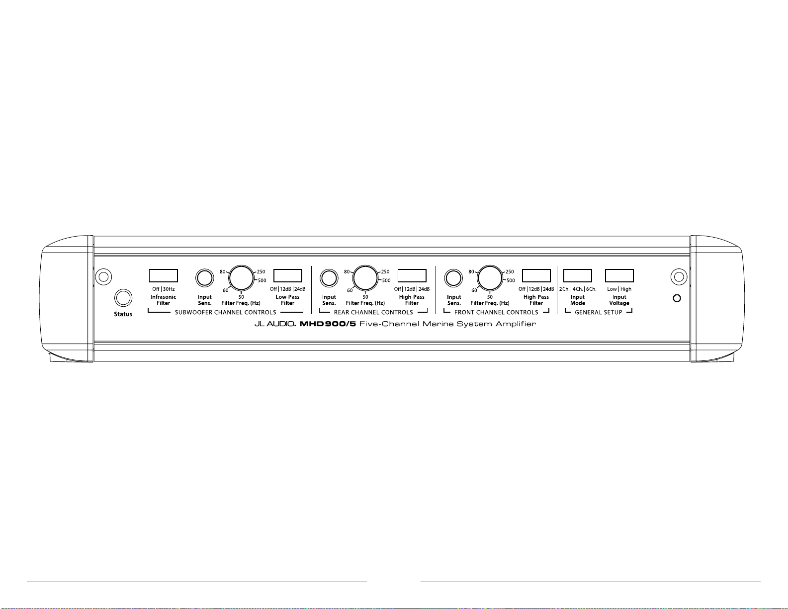
INSTALLATION NOTES:
Use this diagram to document your amplifier’s switch and control positions.
Page 13

LIMITED WARRANTY MARINE PRODUCTS USA
JL AUDIO warrants this product to be free of defects in materials and workmanship for a period of
two (2) years from the original date of purchase.
This warranty is not transferable and applies only to the original purchaser from an authorized
JL AUDIO dealer. Should service be necessary under this warranty for any reason due to manufacturing
defect or malfunction, JL AUDIO will (at its discretion), repair or replace the defective product with new
or remanufactured product at no charge. Damage caused by the following is not covered under warranty:
accident, misuse, abuse, product modification or neglect, failure to follow installation instructions,
unauthorized repair attempts, misrepresentations by the seller. This warranty does not cover incidental
or consequential damages and does not cover the cost of removing or reinstalling the unit(s). Cosmetic
damage due to accident or normal wear and tear is not covered under warranty.
Warranty is void if the product’s serial number has been removed or defaced.
Any applicable implied warranties are limited in duration to the period of the express warranty as
provided herein beginning with the date of the original purchase at retail, and no warranties, whether
express or implied, shall apply to this product thereafter. Some states do not allow limitations on implied
warranties, therefore these exclusions may not apply to you. This warranty gives you specific legal rights,
and you may also have other rights which vary from state to state.
If you need ser vice on your JL AUDIO product:
All warranty returns should be sent to JL AUDIO ’s Amplifier Service Facility freight-prepaid through
an authorized JL AUDIO dealer and must be accompanied by proof of purchase (a copy of the original
sales receipt). Direct returns from consumers or non-authorized dealers will be refused unless specifically
authorized by JL AUDIO with a valid return authorization number.
Warranty expiration on products returned without proof of purchase will be determined from the
manufacturing date code. Coverage may be invalidated as this date is previous to purchase date. Nondefective items received will be returned freight-collect. Customer is responsible for shipping charges and
insurance in sending the product to JL AUDIO. Freight damage on returns is not covered under warranty.
For Service Information in the U.S.A. please call
JL Audio Customer Service: (954) 443-1100
9:00 AM – 5:30 PM (Eastern Time Zone)
JL Audio, Inc
10369 North Commerce Pkwy.
Miramar, FL 33025
(do not send product for repair to this address)
International Warranties:
Products purchased outside the United States of America are covered only
by that countr y’s distributor and not by JL Audio, Inc.
Single-Cycle Control™ (U.S. Patent #6,084,450) is used under exclusive license for mobile audio from Power Physics, Inc. - Newport Beach, CA
MHD900/5MAN-CH-050509
 Loading...