

JL Audio MHD600/4-24V Owner's Manual

OWNER’S MANUAL
4-Channel Class-D Full-Range Marine Amplifier
Thank you for purchasing a JL Audio amplifier for
your marine sound system.
Your amplifier has been designed and manufactured to exacting
standards in order to ensure years of musical enjoyment in your vessel.
For maximum performance, we highly recommend that you have
your new amplifier installed by an authorized JL Audio dealer. Your
authorized dealer has the training, expertise and installation equipment
to ensure optimum performance from this product. Should you
decide to install the amplifier yourself, please take the time
to read this manual thoroughly so as to familiarize yourself
with its installation requirements and setup procedures.
If you have any questions regarding the instructions in this
manual or any aspect of your amplifier’s operation, please contact your
authorized JL Audio dealer for assistance. If you need further assistance,
please call the JL Audio Technical Support Department
at (954) 443-1100 during business hours.
NOT FOR USE IN 12 V SYSTEMS!
2 | JL Audio - MHD600/4-24V Owner’s Manual
PROTECT YOUR HEARING!
We value you as a long-term customer. For
that reason, we urge you to practice restraint in
the operation of this product so as not to damage
your hearing and that of others in your vessel.
Studies have shown that continuous exposure to
high sound pressure levels can lead to permanent
(irreparable) hearing loss. This and all other
high-power amplifiers are capable of producing
such high sound pressure levels when connected
to a speaker system. Please limit your continuous
exposure to high volume levels.
While driving, operate your audio system in
a manner that still allows you to hear necessary
noises to operate your vessel safely (horns,
sirens, etc.).
SERIAL NUMBER
In the event that your amplifier requires
service or is ever stolen, you will need to have
a record of the product’s serial number. Please
take the time to enter that number in the space
provided below. The serial number can be found
on the bottom panel of the amplifier and on the
amplifier packaging.
Serial Number:
INSTALLATION APPLICATIONS
This amplifier is designed for operation in
vessels with 24 volt, negative-ground electrical
systems. Use of this product in vessels with
positive ground and/or voltages other than 24V
may result in damage to the product and will void
the warranty.
This product is not certified or approved for
use in aircraft.
Do not attempt to “bridge” the outputs of this
amplifier with the outputs of a second amplifier,
including an identical one.
PLANNING YOUR INSTALLATION
It is important that you take the time to read
this manual and that you plan out your
installation carefully. The following are some
considerations that you must take into account
when planning your installation.
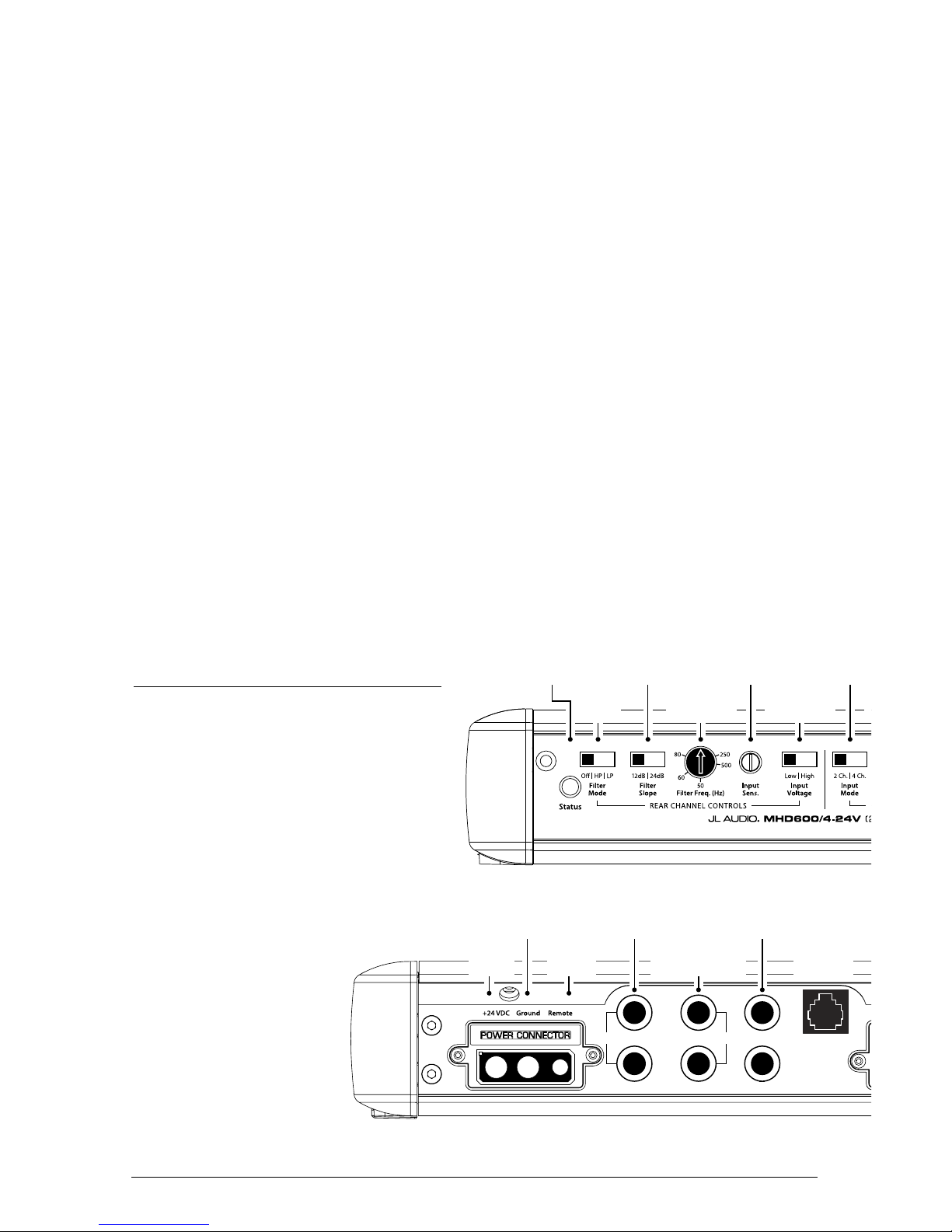
Input Sensitivity
Control
(pg. 10)
Power Status
Indicator
(pg. 16)
Filter Mode
Selection
(pg. 11)
Filter Slope
Selection
(pg. 11)
Filter Frequency
Selector
(pg. 11)
Input Sensitivity
Control
(pg. 10)
Filter Mode
Selection
(pg. 11)
Filter Slope
Selection
(pg. 11)
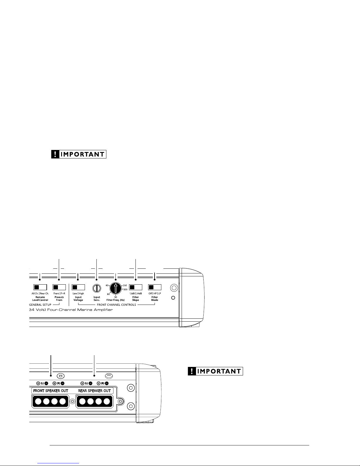
Input Mode
Selection
(pg. 9)
Preouts From
Selection
(pg. 13)
Filter Frequency
Selector
(pg. 11)
Input Voltage
Selection
(pg. 10)
Remote Level
Control
Selection
(pg. 13)
Input Voltage
Selection
(pg. 10)
Rear Preouts
Remote
Level
Control
Front
Inputs
L
R
L
R
Ground Remote
Chassis Ground
Connector
(pgs. 6-7)
Front Left & Right
Channel Input Jacks
(pg. 9)
Left & Right Preamp
Output Jacks
(pg. 13)
Rear Left & Right
Channel Input Jacks
(pg. 9)
Rear
Speaker Outputs
(pgs. 14-15)
Front
Speaker Outputs
(pgs. 14-15)
Jack for
Remote Level
Control Knob
(pg. 13)
Remote Turn-On
Connector
(pgs. 6-7)
+24 V Power
Connector
(pgs. 6-7)
3
Cooling Efficiency Considerations:
The outer shell of your JL Audio amplifier
is designed to remove heat from the amplifier
circuitry. For optimum cooling performance,
this outer shell should be exposed to as large a
volume of air as possible. Enclosing the amplifier
in a small, poorly ventilated chamber can
lead to excessive heat build-up and degraded
performance. If an installation calls for an
enclosure around the amplifier, we recommend
that this enclosure be ventilated with the aid
of a fan. In normal applications, fan-cooling
is not necessary.
Mounting the amplifier upside down is
strongly discouraged.
If mounting the amplifier under a seat,
make sure there is at least 1 inch (2.5 cm) of
space above the amplifier’s outer shell to permit
proper cooling.
Safety Considerations:
Your amplifier needs to be installed in a dry,
well-ventilated environment and in a manner
which does not interfere with your vessel’s factory
installed electronic devices. You should also take
the time to securely mount the amplifier so that
it does not come loose in the event of a collision/
sudden jolt or as a result of the repeated vibrations
the vessel is prone to during normal operation.
Stupid Mistakes to Avoid:
• Check before drilling any holes in your vessel to
make sure that you will not be drilling through
the hull, a fuel tank, fuel line, wiring harness or
other vital vessel system.
• Do not run system wiring outside or underneath
the vessel. This is an extremely dangerous
practice which can result in severe damage to
your vessel and person.
• Protect all system wires from sharp edges
(metal, fiberglass, etc.) by carefully routing
them, tying them down and using grommets
and loom where appropriate.
• Do not mount the amplifier in the engine
compartment or in any other area that will
expose the amplifier circuitry to the elements.
While this amplifier is specially designed
for marine applications, it is not waterproof
and it should not be mounted where it is
likely to get wet.
Input Sensitivity
Control
(pg. 10)
Filter Mode
Selection
(pg. 11)
Filter Slope
Selection
(pg. 11)
Preouts From
Selection
(pg. 13)
Filter Frequency
Selector
(pg. 11)
Remote Level
Control
Selection
(pg. 13)
Input Voltage
Selection
(pg. 10)
Rear
Speaker Outputs
(pgs. 14-15)
Front
Speaker Outputs
(pgs. 14-15)

4 | JL Audio - MHD600/4-24V Owner’s Manual
PRODUCT DESCRIPTION
The JL Audio MHD600/4-24V is a very
powerful and compact four-channel, fullrange amplifier utilizing patented Single Cycle
Control™ Class D technology for all channels.
This groundbreaking technology delivers
reference-grade sonic performance while
requiring far less current from the vessel’s
electrical system than a conventional amplifier.
JL Audio’s exclusive R.I.P.S. power supply
design optimizes the output of each channel pair
for any impedance between 1.5 and 4 ohms per
channel (3-8 ohms bridged) allowing you to get
full use of the MHD600/4-24V’s performance
capabilities with a wide range of speaker systems.
The tightly regulated power supply design also
means that the MHD600/4-24V’s clean power
output capability remains stable over a wide range
of voltages, resulting in enhanced fidelity.
The MHD600/4-24V flexible, studio-grade
signal processing allows it to be deployed in a
wide range of system applications:
1) As a four-channel (150W x 4) full-range
amplifier, delivering full-range signals to two
separate stereo speaker systems (front and rear,
for example).
2) As a powerful (150W x 4) four-channel satellite
amplifier in a bi-amplified system, delivering
high-passed signals to front and rear speaker
systems. Preamp outputs permit connection
of a separate amplifier to drive the subwoofer
system.
3) As a 600W full-system amplifier in
bi-amplified mode with one channel pair
driving subwoofers in low-pass mode (150W
x 2 or 300W x 1) and the other channel pair
driving main speakers in high-pass mode
(150W x 2).
4) As a very powerful (300W x 2) full-range
amplifier, delivering full-range signals to a
stereo speaker system.
5) As a very powerful (300W x 2) two-channel
satellite amplifier in a bi-amplified system,
delivering high-passed signals to a stereo
speaker system. Preamp outputs permit
connection of a separate amplifier to drive the
subwoofer system.
6) As a powerful (300W x 2) two-channel
subwoofer amplifier in a bi-amplified system,
delivering low-passed signals to a dual
subwoofer system. Preamp outputs permit
connection of a separate amplifier to drive the
satellite speakers.
The MHD600/4-24V’s flexible input and
crossover sections permit operation with
a wide variety of source units and system
configurations. It can be operated with a
single pair of stereo inputs or with separate
inputs for its front and rear channels.
The MHD600/4-24V’s preamp output can
send pass-through signals from the Front Inputs
only or it can sum all four input channels to
feed a non-fading signal to a separate subwoofer
amplifier.
As we said, it’s very flexible.

5
TYPICAL INSTALLATION SEQUENCE
The following represents the sequence
for a typical amplifier installation, using
an aftermarket source unit. Additional
steps and different procedures may be
required in some applications. If you
have any questions, please contact your
authorized JL Audio dealer for assistance.
1) Disconnect the negative battery post
connection and secure the disconnected cable
to prevent accidental re-connection during
installation. This step is not optional!
2) Run positive and negative power wire from
the battery location to the amplifier mounting
location, taking care to route it in such a
way that it will not be damaged and will
not interfere with vessel operation. 8 AWG
is recommended for wire runs greater than
72 inches (180 cm) in length. Use a 2 AWG,
4AWG or 8 AWG main power wire with a
power distribution block when additional
amplifiers are being installed with the
MHD600/4-24V and powered from the same
main power wire.
3) Connect power wire to the positive battery
post. Fuse the wire with an appropriate fuse
block (and connectors) within 18 inches (45
cm) wire length of the positive battery post.
This fuse is essential to protect the vessel.
Do not install the fuse until the power wire
has been connected to the amplifier.
4) Connect negative power wire to the negative
battery post. Use the same size power
wire as the wire connected to the “+24V”
connection (minimum 8 AWG).
5) Run signal cables (RCA cables) and remote
turn-on wire from the source unit or interface
processor to the amplifier mounting location.
6) Run speaker wire from the speaker systems to
the amplifier mounting location.
7) Securely mount the amplifier using
appropriate hardware. (See page 8 for detailed
mounting instructions).
8) Connect the remote turn-on wire and the
positive and negative power wires to the
amplifier’s power connector plug. Then insert
the power connector plug into the amplifier’s
power connector receptacle, pushing firmly.
9) Connect the RCA input cables
to the amplifier.
10) Connect the speaker wires to the speaker
connector plugs and insert the plugs firmly
into the speaker connector receptacles.
11) Carefully review the amplifier’s control
settings to make sure that they are set
according to the needs of the system.
12) Install power wire fuse (25A for a
single MHD600/4-24V) and reconnect the
negative
battery post terminal.
13) Turn on the source unit at a low level
to double-check that the amplifier is
configured correctly. Resist the temptation
to crank it up until you have verified the
control settings.
14) Make necessary adjustments to the input
sensitivity controls to obtain the right
overall output and the desired balance
in the system. See Appendix C (pages 18, 19)
for the recommended input sensitivity
setting method.
15) Enjoy the fruits of your labor with your
favorite music.
6 | JL Audio - MHD600/4-24V Owner’s Manual
POWER AND TURNON CONNECTIONS
Before installing the amplifier, disconnect the
negative (ground) wire from the vessel’s battery.
This will prevent accidental damage to the system,
the vessel and your body during installation.
+24V Battery Connection
You will need to connect a power wire to
the vessel’s positive battery terminal, using an
appropriate power ring or specialized battery
terminal connector, such as the JL Audio
XB-BTU. This connection must be tight and
corrosion-free to ensure proper connectivity. This
wire MUST be fused appropriately for safety. Any
positive power wires run through metal, wood or
fiberglass barriers, must be protected with a high
quality insulating grommet to prevent damage
to the insulation of the wire. Failure to do so may
result in a dangerous short circuit.
Power Wire Requirements
The MHD600/4-24V’s “+24 VDC” and
“Ground” connections are designed to accept
8 to 4 AWG power wire. 8 AWG pure copper
wire is the minimum recommended wire size
for this amplifier. Use of smaller gauge wire
(including cheap wire that is fraudulently sold
as 8 AWG wire) can create a fire hazard.
If you are installing the MDH600/4-24V with
other amplifiers and wish to use a single main
power wire, use 4 AWG, 2 AWG or 1/0 AWG pure
copper wire as a main power wire. This larger
power wire should terminate into a distribution
block mounted as close to the amplifiers as
possible and should connect to the MDH600/424V with 8 AWG pure copper power wire, with
each smaller wire fused appropriately for each
amplifier or other electronics in the system.
Please note that lower AWG numbers mean
bigger wire and vice-versa (1/0 AWG is the largest,
2 AWG is smaller, then 4 AWG, then 8 AWG, etc.).
We do not recommend the use of “copper-clad
aluminum wire” or “CCA” wire because this
wire is significantly less conductive than pure
copper wire. Only use pure copper power wire,
such as JL Audio Premium Power Wire. Tinned
copper wire (silver color) is desirable as the tinplating is only a very minor component of the
wire and provides corrosion resistance.
Fuse Requirements
The installation of a fuse on the main power
wire, within 18 wire inches (45 cm) of the positive
battery terminal is vital to protect the wire and
the vehicle from fire in the event of a collision
or short-circuit. The fuse value at each power
wire should be just high enough for all of the
equipment being run from that power wire. Do
not use a fuse with a value that far exceeds the
total fuse rating of the electronics connected to
the wire.
If only the MHD600/4-24V is being run
from that power wire, we recommend a
25A fuse be used. AGU (big glass fuse). AFS
(small blade fuse) or MaxiFuse™ (big plasticbody fuse) types are recommended.
If other amplifiers are also being powered from
a main power wire and exceed 80 amps in total
fuse rating, we recommend the use of an ANL
(large-blade) fuse and holder to protect the main
wire and a fused distribution block to protect the
individual power wires feeding the amplifiers.
Please consult with your JL Audio
dealer to make sure that the wire, fuse
holder and fuse ratings are appropriate
for your system’s needs. The safety of
your installation depends on appropriate
power connections and fuse protection.
Ground Connection
The ground connection should be made using
the same gauge wire as the power connection.
It is common for the alternator to be grounded
through its chassis. If the alternator is not
grounded through its chassis and instead employs
a small (10 AWG - 6 AWG) wire to connect to
ground, this wire should also be upgraded to 4
AWG when installing amplifier systems with main
fuse ratings above 60A.
7
Many vessels employ small (10 AWG - 6 AWG)
wire to ground the battery to the vessel ground
point and to connect the alternator’s positive
connection to the battery. To prevent voltage
drops, these wires should be upgraded to 4
AWG pure copper wire when installing amplifier
systems with main fuse ratings above 60A.
Turn-On Wire
The MHD600/4-24V uses a conventional +12V
or +24V remote turn-on wire, typically controlled
by the source unit’s remote turn-on output. The
amplifier will turn on when +12V or +24V is
present at its “Remote” input and turn off when
+12V or +24V is switched off. If a source unit
does not have a dedicated remote turn-on output,
the amplifier’s turn-on lead can be connected
to +24V via a switch that derives power from an
ignition-switched circuit.
The MHD600/4-24V’s “Remote” turn-on
connector is designed to accept 18 AWG – 12
AWG wire. 18 AWG is more than adequate for
this purpose.
To connect the remote turn-on wire to the
amplifier, first back out the set screw on the
bottom of the Power Connector Plug, using the
supplied hex wrench. Strip 1/2 inch (12mm) of
wire and insert the bare wire into the receptacle,
seating it firmly so that no bare wire is exposed.
When using smaller wire, it may be necessary to
strip 1 inch of insulation from the wire and fold
the bare wire in half prior to insertion. While
holding the wire in the terminal, tighten the
set screw firmly using the supplied 2.5 mm hex
wrench, taking care not to strip the head of the
screw and making sure that the wire is firmly
gripped by the set screw.
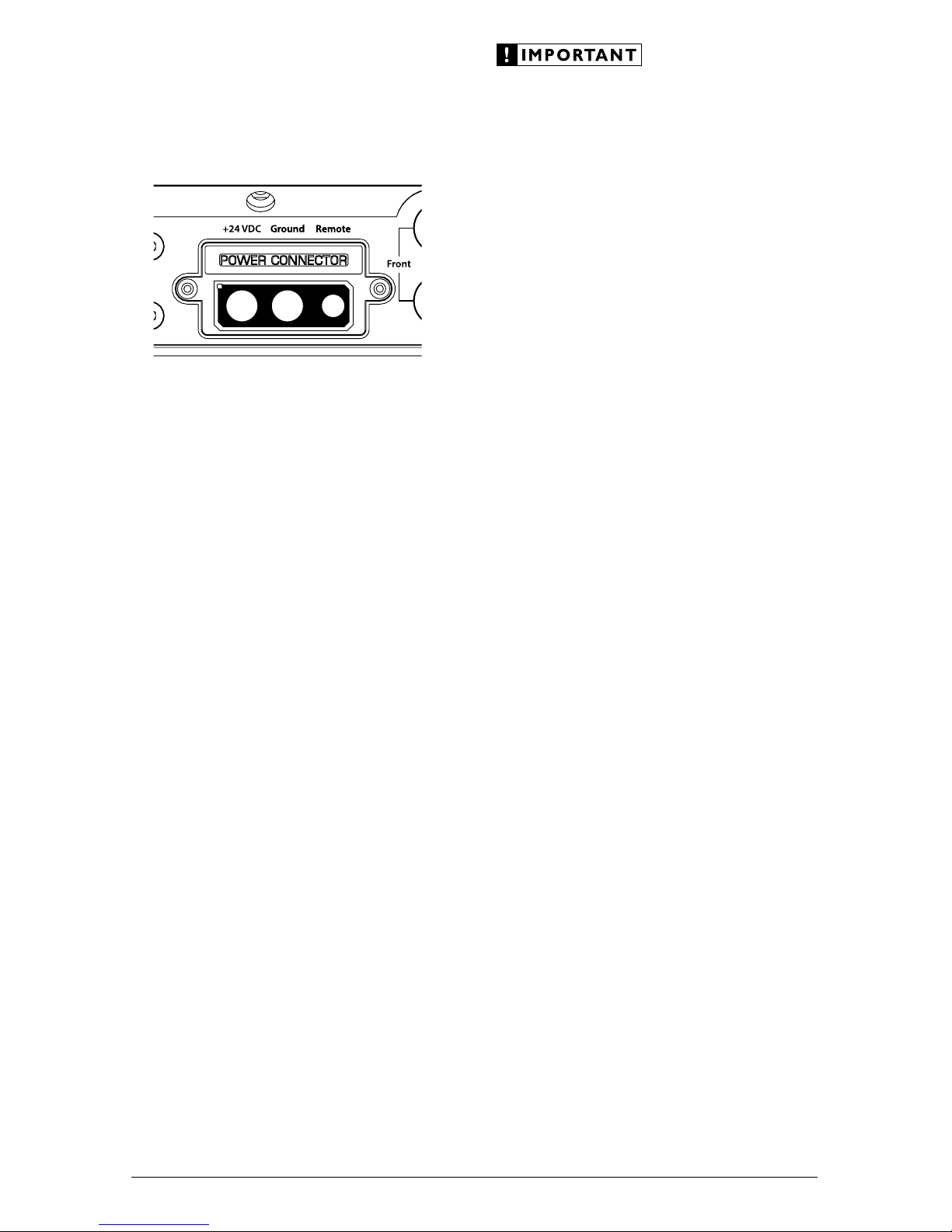
Amplifier Power Connector Plug
To connect the power wires and the remote
turn-on wire to the amplifier, unplug the power
connector plug from the amplifier chassis (pull
back firmly) and back out the set screws on
the connector plug, using the supplied 4 mm
hex wrench for the “+24 VDC ” and “Ground”
connections and the supplied 2.5 mm hex wrench
for the “Remote” connection. Strip 3/8 inch (10
mm) of insulation from the end of each wire and
insert the bare wire into the receptacle on power
connector plug, seating it firmly so that no bare
wire is exposed. While holding each wire in place,
tighten each set screw firmly, taking care not to
strip the head of the screw.
Never make power connections with a “live”
wire. Always disconnect the negative battery
post before making any connections or
adjustments to a 24V power connection!
8 | JL Audio - MHD600/4-24V Owner’s Manual
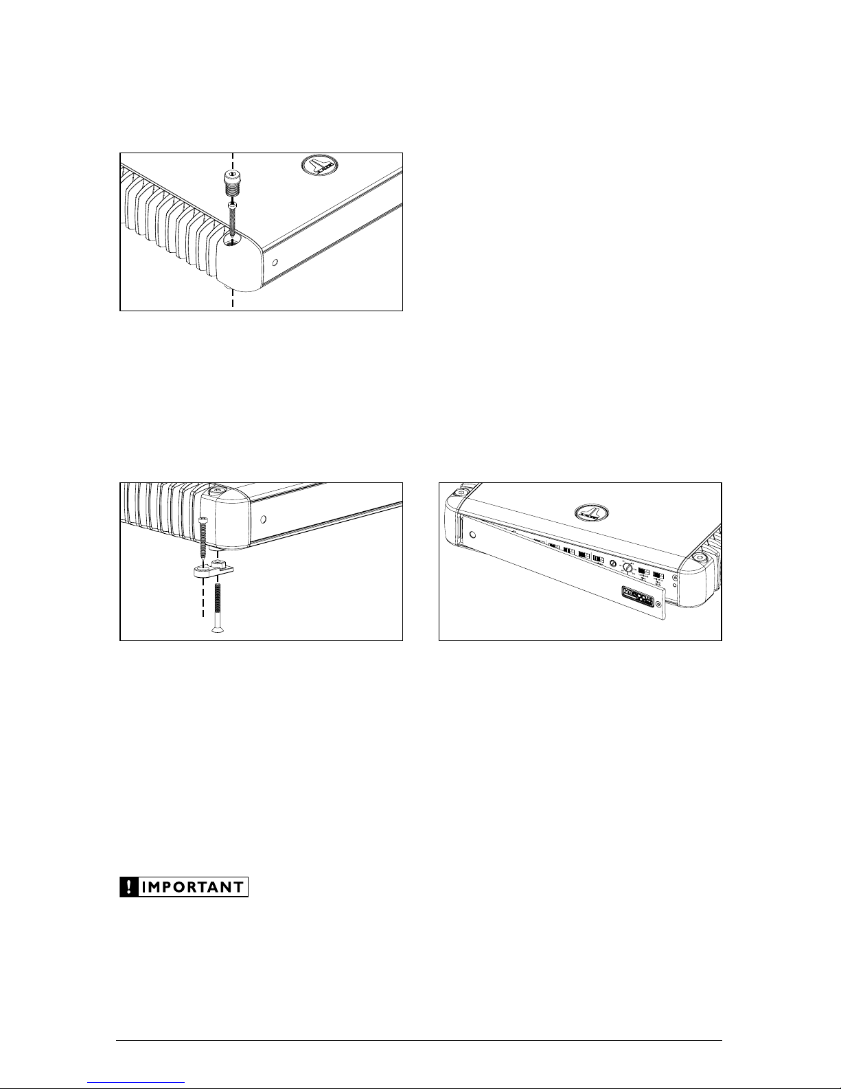
AMPLIFIER MOUNTING OPTIONS
The MHD600/4-24V has two mounting
options to ease in installation.
Standard Mounting
The standard method of mounting requires
removal of the four corner caps with the 3/16inch hex wrench included with your amplifier.
Using appropriate mounting screws (not
included), secure the amplifier in all four corners
and replace the corner caps.
Lateral Mounting Feet
Lateral Mounting Feet are also included
with your MHD600/4-24V to provide an
alternative mounting option. Each mounting
foot should be attached to the bottom of the
amplifier by screwing the provided bolt into
the bottom of the amplifier and up into the
corner cap with the supplied 1/8-inch hex
wrench. Next, using appropriate mounting
screws (not included), secure the amplifier
by its four Lateral Mounting Feet.
Check before drilling any holes in your vessel to
make sure that you will not be drilling through
a gas tank, brake line, wiring harness or other
vital vessel system.
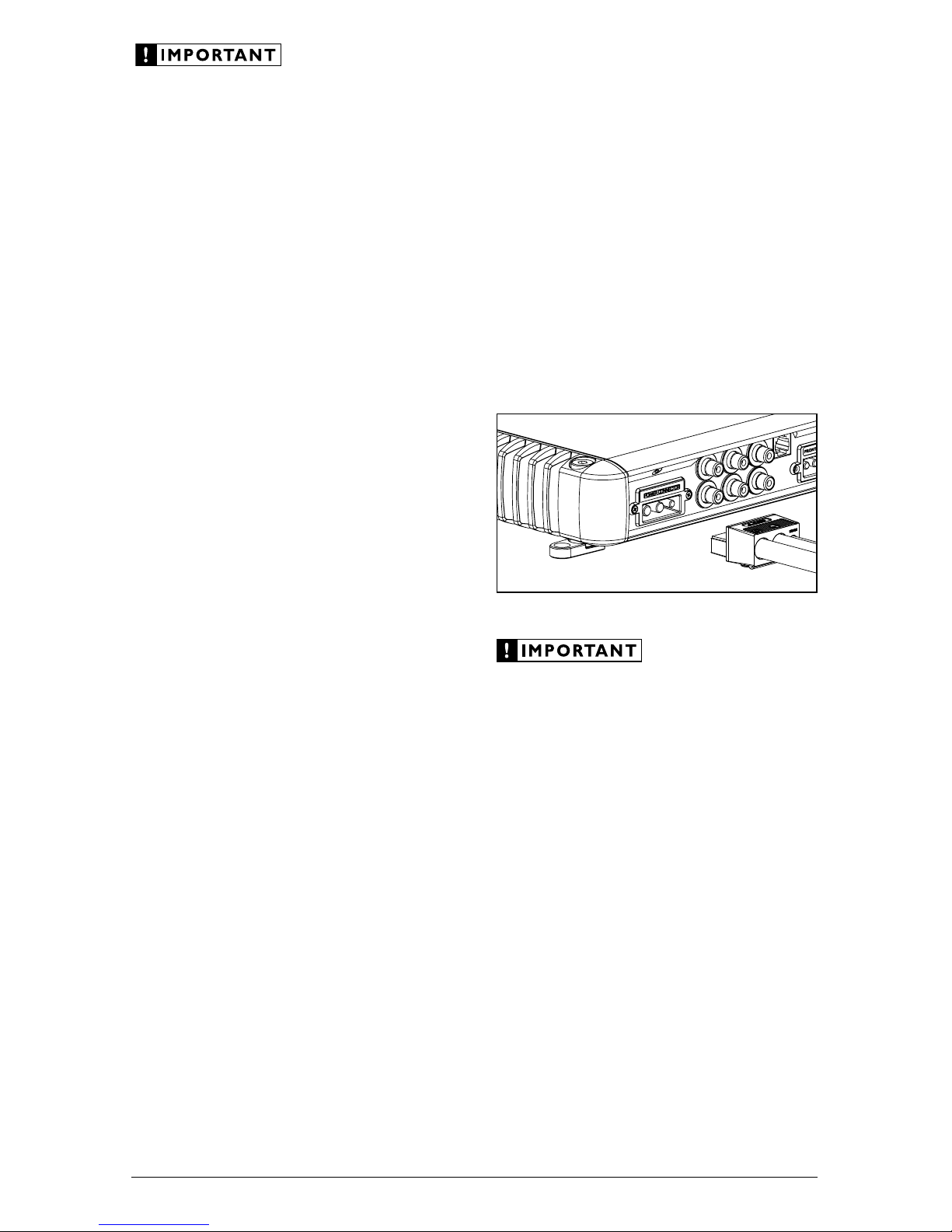
CONTROL PANEL SECURITY COVER
The MHD600/4-24V features a Control Panel
Security Cover. When installed, the cover ensures
that your amplifier settings are not accidentally
changed while creating a clean aesthetic for the
amplifier and your installation. The control panel
security cover is pre-installed at the factory and
must be temporarily removed for access to the
controls described throughout this manual.
The security cover is secured by a single 2.5
mm hex-head screw at the far right of the panel.
Loosen the hex-head screw to release the security
cover (it is not necessary to completely remove the
screw). To re-install the security cover once all
adjustments have been made, insert the tongue on
the cover’s left edge into the groove where the leftside heatsink meets the control panel, hinge the
panel closed and secure the screw using the
supplied 2.5 mm hex wrench. Do not overtighten
the screw.
 Loading...