

JL Audio MediaMaster 50 Owner's Manual

Thank you for purchasing a JL Audio MediaMaster®
Source Unit for your sound system.
This product has been designed and manufactured to exacting
standards in order to deliver years of musical enjoyment. For maximum
performance, we highly recommend that you have your MM50 installed
by an authorized JL Audio dealer. Your authorized dealer has the
training, expertise and installation equipment to ensure optimum
performance from this product. Due to the complexity of modern
vehicle systems, we do not recommend self-installation unless you have
extensive experience in automotive and marine electrical systems.
Should you decide to install this product yourself, please take the time to
read this manual thoroughly to familiarize yourself with its installation
requirements and setup procedures.
If you have any questions regarding the instructions in this manual or
any aspect of the product’s operation, please contact your authorized
JL Audio dealer for assistance. If you need further assistance, please contact
the JL Audio Technical Support Department at technical@jlaudio.com
or call (954) 443–1100 during business hours.
OWNER’S MANUAL

2
Protect Your Hearing!
We value you as a long-term customer.
For that reason, we urge you to practice
restraint in the operation of this product
so as to not damage your hearing and
that of others in your vehicle. Studies
have shown that continuous exposure
to high sound pressure level can lead
to permanent (irreparable) hearing loss.
Mobile sound systems are capable of
producing such high sound pressure
levels. Please limit your continuous
exposure at high volumes. While driving,
operate your audio system in a manner
that still allows you to hear necessary
noises to operate your vehicle/vessel
safely (horns, sirens, etc.).
FCC Compliance Statement
This equipment has been tested and
found to comply with the limits of
Part 15 of the FCC Rules. These limits
are designed to provide reasonable
protection against harmful interference
in a residential installation. This
equipment generates, uses and can
radiate radio frequency energy and,
if not installed in accordance with
the instructions, may cause harmful
interference to radio communications.
However, there is no guarantee
that interference will not occur in a
particular installation. If this equipment
does cause harmful interference to
radio or television reception, the user
is encouraged to try to correct the
interference by one or more of the
following measures:
- Reorient or relocate the receiving
antenna.
- Increase separation between the
equipment and the receiver.
- Connect the equipment to an outlet
on a circuit different from that to
which the receiver is connected.
- Consult the dealer or an experienced
radio/TV technician for help.
Any changes or modifications not
expressly approved by the party
responsible for compliance could
void the user’s authority to operate
this equipment.

3
Safety Considerations
• Install this product in a dry, wellventilated location that does not
interfere with your factory-installed
systems. If a dry environment is not
available, a location that is not exposed
to heavy splashing may be used.
• While this product is designed to be
water-resistant, it should never be
submerged under water or subjected to
high-pressure water spray.
• Do not mount this product in an engine
compartment or areas of extreme heat.
Areas exposed to a heater or hot air
should also be avoided.
• Securely mount this product so that it
does not come loose in the event of a
collision, sudden jolt or as a result of
repeated vibrations during normal use.
• Check before drilling to make sure that
you will not be drilling into an exterior
panel/hull, fuel tank, gas/brake line,
wiring harness or other vital system.
• Do not run system wiring outside or
underneath the vehicle/vessel. This is
an extremely dangerous practice, which
can result in severe damage/injury.
• Protect all system wires from
sharp edges and wear by carefully
routing them, tying them down and
using grommets and loom where
appropriate. Secure all wiring using
cable ties or wire clamps, as needed.
• Do not replace the power wire fuse
with one of a different value.
Never bypass the fuse.
• Never make power connections with a
“live” wire. Failure to make safe, tight,
high-integrity connections can result in
fire and extensive damage.
Installation Applications
This product is designed for operation
with 12 volt, negative-ground electrical
systems. Using this product in systems
with positive ground and/or voltages
other than 12 volts may result in
damage to the product and will void the
warranty. This product is not certified or
approved for use in aircraft.
What Is Included
(1) MediaMaster® MM50 Source Unit
(1) Power Connections Wire Harness
(1) Speaker Outputs Wire Harness
(1) Mounting gasket
(1) Mounting template
(4) Mounting screws
(1) Protective Sun Cover
(1) Owner’s manual
Product Description
The MediaMaster® MM50 is a weatherresistant source unit designed for marine
and powersports applications.

4
The MM50 includes
the following features:
• Water-resistant chassis and display (IP66
rated) is built to withstand the elements
• Intuitive interface with easy-to-read,
high-brightness, 2.8-inch full-color LCD
display with large controls
• Programmable day/night lighting modes
for display, buttons and remote, plus a
dedicated Day/Night toggle button
• Digital AM/FM tuner with RDS (Radio
Data System) to display extended FM
program info, where available
• Quick access to 18 of your
favorite AM/FM stations
• USB direct-digital connection accesses
music files on your USB storage
device or iPhone®
• Bluetooth® v2.1 receives top-quality
audio from compatible devices with
playback control, up to 35 ft. (11 m) away
• 2.1A USB output conveniently charges
your phone or portable music player
• Auxiliary inputs accept audio
signals from any source with
line-level outputs
• NMEA 2000® Certified - MFD (Multi-
Function Display) control functionality
via vessel networks (Refer to MFD
manufacturer for device compatibility.)
• User customizable naming for display on
Bluetooth® devices and MFDs
• Built-in amplifier generates 100 watts of
high-fidelity power (25W RMS x 4)
• Two sets of 4V RMS line-level outputs
deliver crystal-clear audio signals
to your amplifiers, plus dedicated
subwoofer outputs
• Both Zone 1 and 2 output types (speaker
and line-level) feature onboard highpass crossover with frequency selection
(off/60/80/100/150 Hz)
• Subwoofer zone outputs equipped with
a 500 Hz low-pass crossover
• Configureable zone feature/control
options include:
Level Control Mode options for on-the-
fly volume adjustments of all zones,
together or individually. Each zone can
be independently configured as:
- Variable: The volume knob adjusts
all zones simutaneously, with
independent control of each zone’s
relative offset level.
- Fixed: Sets the output level of selected
zones at a specific output voltage (4V,
2V or 1V RMS) that is not affected by
the volume control.
- Off: Disables the output level of
selected zones.
Tone Control Mode options allow
customization of treble, midrange, bass
and balance settings as:
- Same as Zone 1: Links the controls of
with Zone 1.
- Independent Tone Control maintains
separate control.
Volume Limit allows you to set a
custom, maximum allowable volume
level for each zone.
Rename Zone permits the creation of
custom names for each zone, or choose
from a list of preset location names.
Subwoofer zone’s level and tone
controls can be linked to proportionally
track (follow) Zone 1 or 2 or disabled.
The offset level of volume for each zone
is independently adjustable
• Three remote controller options
available: (each sold separately)
- MMR-10W Wireless, Waterproof
Remote Controller (key-fob style)
- MMR-20-BE Wired Remote Controller
- MMR-40 Full-Function NMEA 2000®
Network Controller with LCD display
5
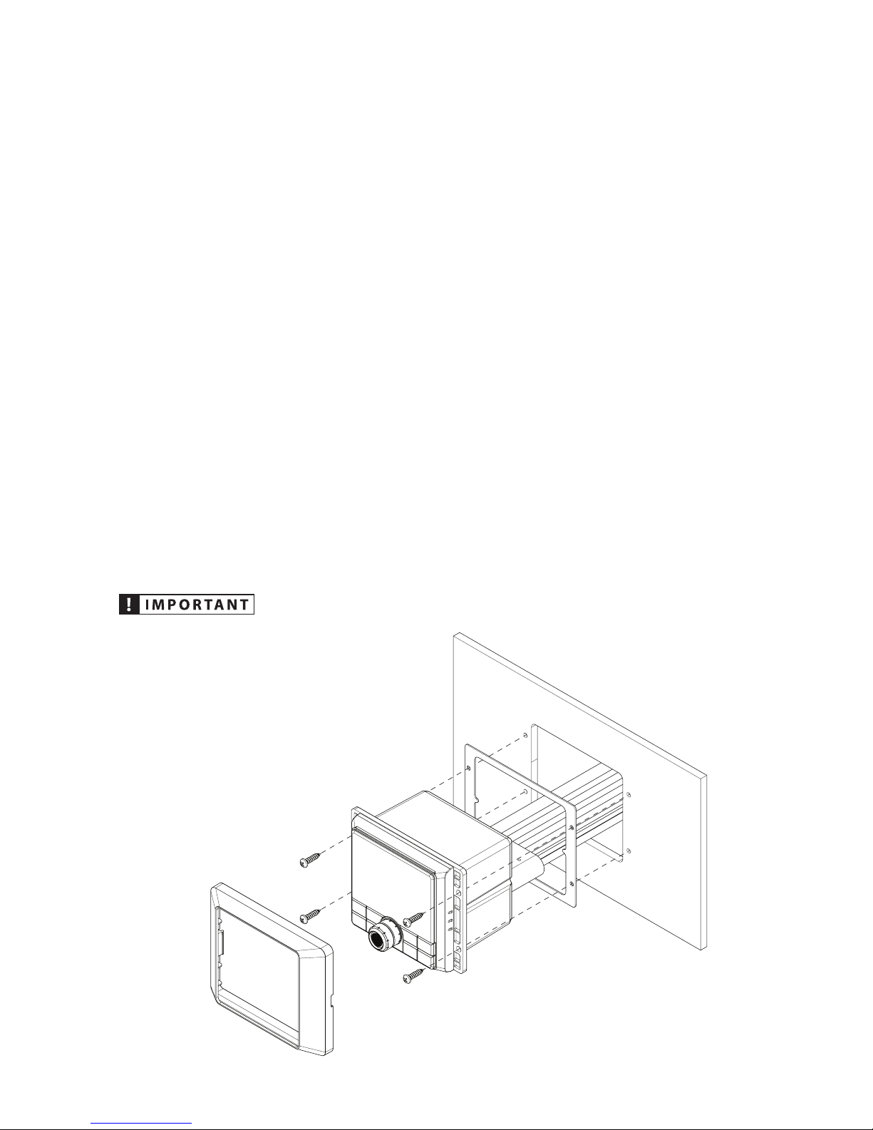
MOUNTING AND INSTALLATION
The diagram below shows a typical
mounting procedure into a fiberglass
panel. Always follow proper safety
procedures. Wear eye-protection
at all times with a dust mask and
gloves when cutting. A mounting
template is included to aid in
measuring and marking the mounting
surface before cutting or drilling.
1. Press along the perforation to
remove the center section of the
mounting template. (Discard the
center section.) The template can
be used to verify there is sufficient
flat surface area for mounting
and as a guide for cutting the
opening. Tape the template
to the mounting location and
mark the surface for cutting the
opening and drilling pilot holes.
2. Use a jigsaw or rotary tool to cut an
opening in the mounting surface.
If necessary, use a file or sandpaper
to adjust the opening for proper
fitment and smooth the edges.
3. Place the MM50 into the opening
and check that the mounting
holes remain aligned with the
pilot hole marks taken from
the template. If not, adjust and
mark new holes as necessary.
4. Remove the MM50 and drill four
(4) pilot holes in the mounting
surface at the pilot hole marks.
5. Peel the adhesive backing
from the mounting gasket and
affix to the rear of the bezel.
Connect all wiring and place
the MM50 into the opening.
6. Secure the MM50 using the four
(4) mounting screws. Press the trim
ring onto the front of the MM50.
Before drilling or cutting, make
sure there is adequate space behind
the mounting surface to fit the MM50,
including its
wire harness.
6
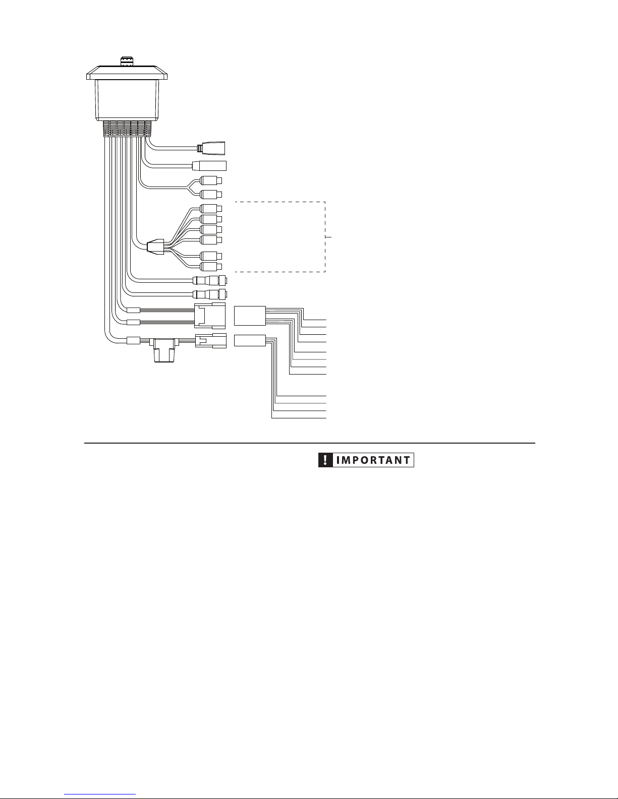
AUX-IN – To PreAmp Aux Source
ZONE 1&2 SPEAKER OUTPUTS
POWER CONNECTIONS
REMOTE – MediaMaster® MMR-20-BE or MMR-10W Remote Controllers (Sold Separately)
NMEA LEN 1 – NMEA 2000® Network (Micro-C connector)
ANT – Motorola® Style Antenna
ZONE1
ZONE2
SUBWOOFER
+12VDC (Red) – Switched +12V Power
ILLUMINATION (Orange) – +12V Lighting Circuit
GROUND (Black) – Ground
AMP TURN-ON (Blue) – Remote Output to Amplier
Z2 L + (Green) – Zone 2 Left Speaker Positive
Z2 L – (Green/Black) – Zone 2 Left Speaker Negative
Z2 R + (Purple) – Zone 2 Right Speaker Positive
Z2 R – (Purple/Black) – Zone 2 Right Speaker Negative
Z1 L + (White) – Zone 1 Left Speaker Positive
Z1 L – (White/Black) – Zone 1 Left Speaker Negative
Z1 R + (Gray) – Zone 1 Right Speaker Positive
Z1 R – (Gray/Black) – Zone 1 Right Speaker Negative
To Amplier
15A Fuse
USB – USB Storage Media or iPhone® 5 or beyond
GENERAL CONNECTIONS
WIRING HARNESS CONNECTIONS
Harnesses exiting the rear of the unit are
used to connect to speakers, aftermarket
amplifiers/equipment and media
devices. Depending on your specific
equipment, you may or may not use
all of the connections. Make sure to
plan the layout of your system prior to
routing wires and making connections.
Refer to the table at right for details.
Disconnect the NEGATIVE battery
post connection and secure the
disconnected cable to prevent
accidental reconnection. This is
an essential safety precaution
during installation!
 Loading...