

Page 1
MCS-3000 Series
Media Command Stations
User Reference Manual
Second Edition
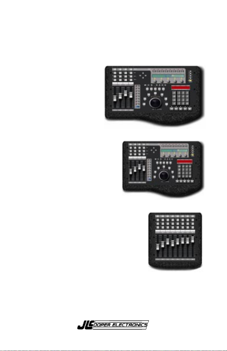
MCS-3800 Controller
MCS-3400 Controller
MCS-3000X Expander
Page 2

Important:
Certain audio and video systems have been engineered to
specifically support the MCS-3000 series. The MCS-3000 series
was selected by the manufacturers of those systems to be their
ideal, de facto control station.
Please review the owners manuals and “read me” files that
came with your audio or video system for references to the
JLCooper MCS-3000 series.
MCS-3000 Series Users Manual Second Edition
JLCooper part number for this manual: 932073
© 1998 JLCooper Electronics
142 Arena Street • El Segundo, CA 90245 U.S.A.
MCS-3000, MCS-3800, MCS-3400, MCS-3000X, Media Control Station,
and Media Command Station are trademarks of JLCooper Electronics.
All other brand names are the property of their respective holders.
About this Manual
This manual tends toward a pyramidal structure.
Essential concepts are presented first, followed by instructions with
increasing amounts of detail. This allows the user to read as much as he or
she needs, and then bail out and get back to work.
This manual is also intentionally repetitious.
The same basic concepts about programming and operation tend to be
repeated in every chapter, and sometimes more than once within a chapter
where appropriate.
This re-enforces the concepts, but more importantly lets the user work with
the MCS-3000 series controller with only one page of the manual open at a
time, while minimizing having to hold the manual open to ten different
places at the same time.
2
Page 3

Introduction
The MCS-3000 series of control stations are the most advanced
control products ever from JLCooper Electronics. This family of
products includes the 8 fader MCS-3800 Controller, the 4 fader
MCS-3400 Controller, the MCS-3000X 8 fader Expander, and
the Surround Panner Module.
MCS-3800 and MCS-3400 Media Command Stations are moving
fader control surfaces, expandable to sixty-four faders.
Capable of controlling digital workstations for music and video
production and post production, the MCS-3000 series is fully
assignable and simple to operate.
MIDI I/O is standard. In addition, the MCS-3400 and MCS-3800
feature two expansion slots for optional cards which support
other hardware interfaces and protocols. These include RS-232,
RS-422, RS-485, P2 (9 Pin), ADB, and GPI.
This manual deals primarily with the MCS-3400 and MCS-3800
Controllers, and the MCS-3000X Expander, with standard MIDI
I/O. The Surround Panner, and Option Cards are discussed in
their own manuals.
Sending your product registration card allows us to notify you
of any updates or related products as they become available.
Important
on the last 7 pages of this manual. This is a brief summary of
the whole manual.
: There is a "Quick Operation Reference" found
3
Page 4

Table of Contents
Introduction............................................................. 3
Getting Started ......................................................... 7
This chapter discusses the MCS-3000 Series hardware,
describing the front and rear panel controls, viewing the front
panel in "sections", the displays and connectors, and how to
interconnect it into your system.
Front Panel Displays and Controls............................7
Rear Panel ................................................................11
Expander Connection..............................................13
Hardware ...........................................................14
Electrical.............................................................15
Set ID with DIP Switch ......................................16
System Connections ................................................18
Power .................................................................18
Time Code..........................................................18
MIDI I/O ............................................................19
Card Slots ...........................................................19
OMS and FreeMIDI Definitions...............................20
Basic Operation .....................................................21
This chapter discusses some fundamental characteristics of the
MCS-3000 Series, what it does when powered up, operating
modes, and the ever-popular wave demo.
Power Up .................................................................21
Entering and Exiting Assign Mode ..........................21
LCD and Page Buttons.............................................22
Modes of Operation (User and Special)..................22
LED Behavior In Special Mode ...............................24
Manually Exiting Special Mode ...............................25
Wave Demo .............................................................26
4
Page 5

The Mixer Section..................................................27
This chapter discusses how to assign and use the motorized,
touch sensitive faders, their associated channel switches above
the faders, select buttons and rotary encoders, Page and Bank
buttons.
Attributes of the Mixer Section ................................27
Basic Bank Switching and Encoder Selection... 28
Fader Output and Input.....................................29
Touch Sensors....................................................29
Channel Switches...............................................30
Encoders, Select, and Page................................31
Assigning Mixer Controls, and Overview ...............32
To Assign Faders and Touch Sensors .....................33
Editable Parameters of Faders and Touch ..............34
To Assign the Rotary Encoders ...............................36
Editable Parameters of Rotary Encoders .................37
To Assign Mute, Solo, Aux, and Sel ........................38
Editable Parameters of Mute, Solo, Aux, and Sel....39
Mixer Operation Notes ...........................................41
The Transport Section...........................................47
This chapter discusses how to use the Transport controls, Jog
and Shuttle, the Machine Enable (“M”) buttons, and the Keypad
Locate Mode.
Attributes of Transport Section................................47
M Buttons ...........................................................48
Transports ..........................................................49
Jog Wheel and Shuttle Ring ...............................49
Locates ...............................................................50
Assigning Transport Controls, and Overview.........51
Editable Parameters for Transport and M Buttons..53
Command Types......................................................54
Transport Operation................................................57
Jog / Shuttle Operation............................................59
Jog / Shuttle Speed ..................................................61
Locate Operation .....................................................62
5
Page 6

The Function Buttons Section .............................. 65
This chapter discusses how to use the assignable
F buttons, W Buttons, the Cursor Buttons and M buttons.
Attributes of Function Buttons ................................65
Assigning Function Buttons, an Overview .............67
To Assign F and M Buttons .....................................68
Editable Parameters of F and M Buttons................. 69
F and M Button Command Types ...........................70
To Assign W and Cursor Buttons ............................73
Editable Parameters of W and Cursor Buttons........74
Function Button Operation Notes...........................76
The System Section................................................77
This chapter discusses Utility Mode And Keypad Program
Change Mode, the LCD and LED Time Code Display.
Utility Mode .............................................................77
Manually Exiting Special Mode .........................78
Memory Protect..................................................78
Dump .................................................................78
Show TC.............................................................79
Bank Name ........................................................79
Offset (Feet and Frames) ...................................79
Jog and Shuttle Speed........................................80
Program Change Mode............................................81
Time Code Display ..................................................82
Display TC and Locates or Program Changes...82
Show SMPTE, No Frames, Feet : Frame ............ 82
Technical Information .......................................... 83
Dimensions ..............................................................83
Initialization Procedure ...........................................84
Initialized Settings....................................................84
Warranty ................................................................89
Quick Operation Reference (7 Page Summary) .. 90
6
Page 7
Getting Started
This chapter discusses the MCS-3000 Series hardware,
describing the front and rear panel controls, viewing the front
panel in "sections", the displays and connectors, and how to
interconnect it into your system.
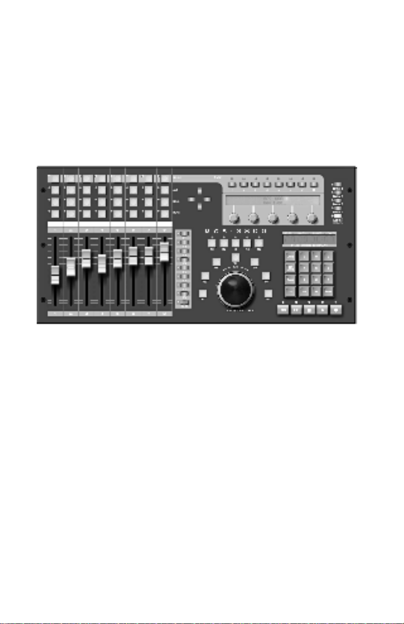
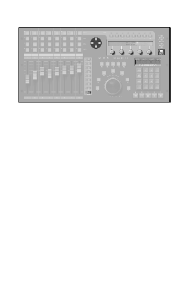
Front Panel Displays and Controls
The illustrations show the MCS-3800, which is operationally the
same as the MCS-3400.
It is helpful when considering the front panel layout to view
the MCS-3800 or MCS-3400 in sections.
Some of the sections “overlap”, there are controls that can be
used for more than one purpose. But viewing the unit in
sections makes it easier to understand.
The displays and controls within the section under discussion
are shown in the following illustrations by "graying out" the
controls that are not part of the section under discussion.
7
Page 8
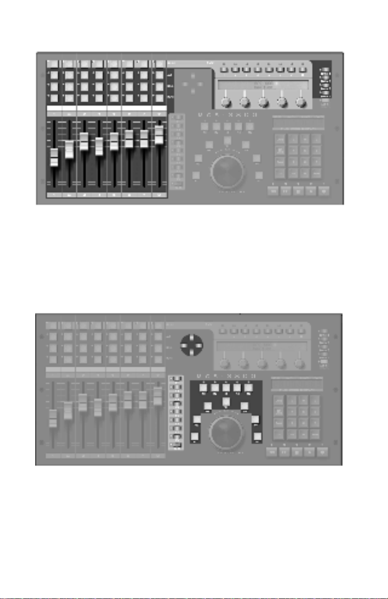
The Mixer Section
The Mixer Section is comprised of the motorized, touch
sensitive faders, the buttons above the faders, the five rotary
encoders, and the Page and Bank Switches.
The Function Buttons Section
This is comprised of the buttons F1 through F8, Shift,
W1 through W5, M1 through M5, the Cursor Buttons.
8
Page 9
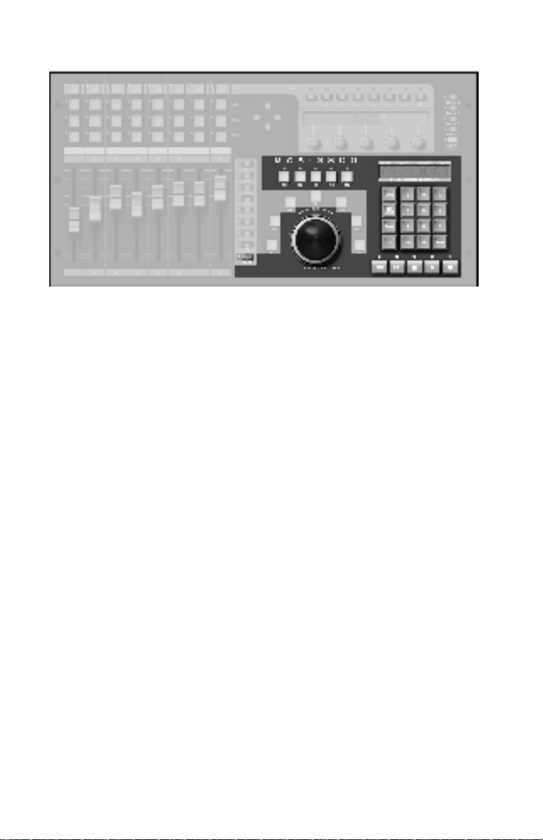
The Transport Section
The Transport Section is comprised primarily of the Transport
Controls: Rewind, Fast Forward, Stop, Play and Record, and
also the Jog / Shuttle mechanism.
Other controls that can be considered part of the Transport
Section include the Keypad, since once of its functions is to
send Locate commands.
The M buttons may be used to turn machines on and off, to
determine, for example, which machines will go into Play
when Play is pressed.
The Shift button is included, because the Transport and M
buttons have Shifted functions as well.
For example, Play can start a hard disk recorder, while Shift
Play starts a VTR.
9
Page 10
The System Section
The System Section is comprised of the Cursor Buttons, the
Rotary Encoders, and the Assign Button.
The Shift button is included, because Shift Assign puts the unit
into Utility mode, and Shift Locate changes the function of the
Keypad from Locates to Program Changes.
The LCD is used to primarily to display the names of controls
and their parameters, locates and system settings.
The LED Display is used primarily for displaying time code.
Time code is displayed as SMPTE time (with or without frames)
or Feet and Frames. The right most decimal point lights when
drop frame code is received.
The display also shows Program Change, Bank, and Channel
number when in Program Change mode.
10
Page 11

Rear Panel
MCS-3800 is shown, the MCS-3400 is similar.
From left to right we have:
• MIDI In, MIDI Out
• LCD Contrast Control
• MCS-3000X Expander Connector
• Time Code Input
The input jack is 1/4”, unbalanced, that is, tip & sleeve.
• Card Slot #1 and Card Slot #2
Accepts optional, user installable plug in cards for additional
control.
• Power Jack
This supply is 12 Volts DC, at least 3A.
The strain relief clip adjacent to the jack may be used to loop
the power cord through to prevent accidental unplugging.
• Power Switch
Flip up (red showing) to turn power on.
11
Page 12

12 85
Page 13
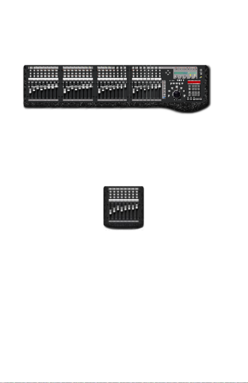
Expander Connection
The MCS-3000X Expanders may be physically attached to the
MCS-3400 or MCS-3800 Controller, forming a continuous
control surface.
(MCS-3800 shown with 3 MCS-3000X Expanders attached)
Alternately, the Expander can stand apart from the MCS
Controller. In that case, an optional set of simulated stone endbells may be purchased to make the Expander more attractive.
(MCS-3000X shown with Optional End Bells attached.)
The instructions for physical interconnection, and electrical
hookup are on the following pages.
13
Page 14

Mounting MCS-3000X Expander to Controller
Important: Make All Connections with the Power Off.
Turn the power off of all MCS-3000 units before proceeding.
Plan Work Area
You will want to work at a spacious, well lit surface.
Spread a cloth on the surface to avoid scratching units.
Remove Top of MCS-3400 or MCS-3800 Controller
Using the allen key provided with the Expander, remove the
six top panel screws of the Controller. Remove any optional
Cards from the card slots. Remove one screw under front
center. Lift the whole top panel, a little forward and up. Invert
and lay control-side down on a soft surface. (Circuit side up.)
Remove Top of MCS-3000X
Remove the six top panel screws of the Controller.
Lift top panel, a little forward and up. Invert and lay controlside down on a soft surface. (Circuit side up.)
Move Left End Bell
Remove the two screws that secure Controller's left end bell.
(These screws will be tight). Attach the left end bell to the left
side of the Expander.
Connect Controller to Expander with Plates Provided
Place the Expander to the left of the Controller, side by side.
Attach the thicker plate to the bottom of both units.
Lay thin (spring steel) plate on top of both units.
Replace top panels of the Controller, guiding in the Time Code
jack and the LCD Contrast control into their holes. Replace the
top panel of the Expander. Replace top screws. Replace
Controller bottom screw. Replace any optional Cards in their
card slots.
14
Page 15

3000X Expander Electrical Hookup
Important: Make All Connections with the Power Off.
Turn the power off of all MCS-3000 units before proceeding.
The 3000X (8 moving fader controller) can be used either:
(1) Connected to an MCS-3800 (or 3400) or
(2) “Stand Alone”, as a self contained control surface.
On the rear of the Expander is a small cluster of four switches,
known as DIP switches.
(1) To connect to an MCS-3800 or, an MCS-3400
Set the rear DIP switch position #4 up (= off).
When the rear dip switch number 4 is up, that is, off, the
MCS-3000X is connected to the MCS-3800 via its Modular
“telephone-type” connectors. The MCS-3000X’s are connected
by chaining them together with the supplied 4-conductor
modular cables.
Connect Expander to Expander in a similar manner, using the
cables provided.
The system is engineered so that it does not matter which of
the two connectors you use, nor in what order you chain the
expanders.
Warning: Use the cable provided with the 3000X. Do not use
a standard “telephone handset” cable. If you use a standard
“telephone handset” cable, you will short out and possibly
damage the MCS-3800 or MCS-3000X. (Note that pin 1 always
goes to pin 1.)
The data comes out of the MCS-3800, not the 3000X MIDI
input and MIDI output.
15
Page 16

Set the Expander ID#
On the rear of the Expander is a small cluster of four switches,
known as DIP switches.
When the rear dip switch number 4 is up, that is, off, the 3
remaining switches are used to set the “ID” number of the
3000X Expander.
These switches set the ID# of each Expander, so the system
knows which Expander represents channels 1 through 8,
which is 9 through 16, etc.
Set the left-most Expander for ID#1 by making sure that
all four switches are up, that is, off.
Follow this chart to set the ID# of multiple units. Off = Up
#4 #3 #2 #1 ID# Fader Numbers
off off off off 1 9 - 16
off off off on 2 17- 24
off off on off 3 25- 32
off off on on 4 33- 40
off on off off 5 41- 48
off on off on 6 49- 56
off on on off 7 57- 64
Important: Be Sure Each Expander has a Unique ID#
A multiple expander system will not operate correctly if two or
more units are set to the same ID#.
On power-up, turn the Expanders on before the MCS-3800.
The MCS-3800 LCD will display the number of 3000X units
connected.
16
Page 17

(2) To Use 3000X “Stand Alone” without an MCS-3800
Set the rear DIP switch position #4 down (= ON)
When the rear dip switch number 4 is down, that is, on, you
will use the MCS-3000X’s MIDI input and MIDI output.
(The MCS-3000X’s modular “telephone-type” connectors are
not used in this modes)
When the rear dip switch number 4 is down, that is, on, the 3
remaining switches are used to select the protocol, that is, the
input and output MIDI commands.
Information about the stand-alone protocols is covered in a
separate document.
DIP Switch Setttings for Protocol Selection
Note that the switches are mounted upside down.
Switch #4 is the left most switch, when viewed from the rear.
Up = off.
#4 #3 #2 #1 Mode
on off off off 0
on off off on 1
on off on off 2
on off on on 3
on on off off 4
on on off on 5
17
Page 18

System Connections
Power
Make sure the power switch is off before connecting the
external power supply.
Power should be turned off of every MCS-3000X Expander.
There is a strain relief clip on the back of the unit, to prevent
accidental unplugging.
Pass the small plug end of the power supply through this clip.
Loop it around and pass it through again..
Then plug it in.
Time Code
The MCS-3400 and MCS-3800 have a built in time code reader
and display.
If you wish to display time code, connect a source of SMPTE
("LTC") to the Sync In jack.
The input jack is 1/4”, unbalanced, that is, tip and sleeve.
While the time code reader responds to a fairly wide range of
input levels, -10 dBm is the recommended nominal level.
18
Page 19

MIDI In and Out
Connect the MIDI Out to the MIDI In of the System you are
controlling.
Connect the MIDI In to the MIDI Out of the System you are
controlling.
If a computer-based system, this will be connected to the
computer’s MIDI Interface.
If a non-computer based system, you may want to connect the
MIDI In and MIDI Out to a MIDI Patch Bay (Such as the
JLCooper Synapse) to distribute the commands throughout the
system.
(The Synapse is a Assignable MIDI Patch Bay / Processor, with
16 MIDI Inputs and 20 MIDI Outputs.)
Card Slots #1 and #2
Connection of Optional Cards are covered in their own
manual.
19
Page 20

OMS or Free MIDI Definitions
If your computer system requires OMS or FreeMIDI, it will also
require that you edit your studio setup to include the MCS.
The MCS-3400 and MCS-3800 are defined in the same way:
MIDI Controllers that transmit on all MIDI Channels. They send
MIDI Machine Control and can also receive MIDI Time Code.
Typical devices descriptions are shown here.
(FreeMIDI Device Specifications Window)
(OMS Device Info Window)
20 77
Page 21

Basic Operation
This chapter discusses some fundamental characteristics of the
MCS-3000 Series, what it does when powered up, operating
modes, and the ever-popular wave demo.
Power Up
Turn the power switch on.
The LCD briefly shows the product name and
The LCD then shows either the current Bank name, or the
name and value of the 5 encoders. If the user has not yet
named the encoders, the display is VKNOB1, VKNOB2, etc.,
After about 2 seconds, the faders will quickly move to the last
position that they held on the previous power down.
Entering and Exiting Assign Mode
The MCS Controller is ready to transmit commands.
While the procedure for assigning a control is described in
detail later, it is important to notice that the unit will not
transmit data while it is in “Assign Mode”.
firmware version.
To enter Assign mode, press the yellow Assign button.
The yellow LED lights.
To exit Assign mode, without any changes to memory, press
Assign again. The yellow LED turns off.
To exit Assign mode, and keep any changes, press Enter on the
numeric Keypad. Then press Assign.
21
Page 22

LCD and Page Buttons
If the already selected Page button is pressed, its LED will turn
off and the LCD shows the Bank name. Press any Page button
to restore the LCD to a display of the encoder names and
values.
If connected to an audio or video host system, developed to
communicate directly the MCS Controller, the LCD may also
change when the host system is launched.
The display is then taken over by the host.
In that case, refer to the documentation of the host system for
information about what appears in the display.
Modes of Operation
The MCS-3000 Series Controllers feature MIDI I/O standard.
There are two fundamentally different modes of MIDI
operation.
(1) The MCS Controller is “user-assignable”, with local control
ON. We’ll call this User Assignable Mode.
(2) The MCS Controller is not “user-assignable”, and local
control is OFF. We’ll call this Special Mode.
When in User Assignable Mode, you can assign each control
yourself. You chose what MIDI command the controls send.
When in Special Mode, you cannot program the unit.
The MCS Controller relies on the implementation of the host
system. The MCS Controller sends special, proprietary
commands to the software host system. The host system
determines what each control will do.
22
Page 23

More About User Assignable Mode
The MCS Controller normally powers up in User Assignable
mode. The expression, “local control on” simply means that
you can push a button and generally expect its LED to turn on.
The LED can be assigned by the user to be either momentary,
or latched.
Momentary means the LED is lit only while the button is
pressed. It turns off when you release the button.
Latched means that the LED turns on with the first button press,
and then turns off with the second button press.
More About Special Mode
The MCS Controller normally first powers up in User
Assignable mode. For Special Modes to be engaged, the host
system has to have been specifically developed to support
Special Mode. Assuming that two way communication is
established, when the host system is launched, it sends a
command into the MCS, which switches it into Special Mode.
The host system then determines what appears in the LCD and
LED displays, and what each control does.
The expression “local control off”, simply means that the
buttons are no longer “tied to” their LEDs. Pressing a button
does not necessarily turn on the LED.
Rather, pressing a button sends a command to the host system.
The host system then is responsible for sending a command
back into the MCS controller, to light up the LEDs.
That way, depending upon the mode of the host system, the
host system may cause an LED to appear to be controlled by
the switch.
23
Page 24

LED Behavior in Special Mode
The LED can appear to behave either momentary, or latched.
Momentary means the LED is lit only while the button is
pressed. It turns off when you release the button. Latched
means that the LED turns on with the first button press, and
then turns off with the second button press. Alternately, the
LED can flash, or do nothing. It is up to the host system.
The most important thing to understand about the Special
Mode, and the fact that the Special Mode turns Local Control
Off, is that two way communication with the host system is
required for a special mode to operate. In other words, special
mode will not work unless there are (in the case of MIDI I/O)
two MIDI cables connected, or a 422 connection.
If only one way communication is established, and the MCS is
in Special Mode, then it is possible that the unit will appear to
not work. Either the displays will light, but the MCS will not
control the software, or, the MCS will control the software but
none of the LEDs or LCD will light.
24
Page 25

Manually Exiting Special Mode
A host software system, engineered to support the MCS
Controller using Special Mode, will send a command which
switches the unit into Special Mode.
At this point, the MCS is no longer user-programmable.
The user may choose, however, to manually exit the Special
Mode and return to User Assignable mode, without having to
turn the hardware off and on.
This is done by entering Utility Mode by pressing Shift and
Assign. Above the first encoder is the word MODE. The
encoder is turned to select either User or Host.
Selecting User returns the unit to User Assignable Mode.
Selecting Host returns the unit to the Special Mode.
Note that this function is only available if the MCS has already
been switched into Special Mode by an external host system.
If the unit has not received any command from a Host system,
since its last power-up, then this feature is not accessible.
User Assignable vs. Pre-Defined Functionality
User Assignable Mode means the unit is User Assignable:
The MCS Controller's MIDI Commands sent are chosen by the
user. You can add a 422 card, and also have 9 Pin control, this
relates to the Transports, Jog/Shuttle, and Locates. You can
also add an ADB card, (Apple Desktop Bus) for Macintosh, and
again the controls are fully assignable.
Special Mode means the unit has a Pre-Defined Functionality:
When communicating via MIDI, RS422, and RS485, the people
who designed your audio and video host system decided how
the MCS Controller behaves. They take over all the controls
and displays, and determine how each control will behave.
25
Page 26

Wave Demo
For the fader wave demo, hold the UP cursor button while
powering up the unit. Continue to hold it for about 3 seconds,
until the demo starts. Turn the power off to stop the demo.
26
Page 27

The Mixer Section
This chapter discusses how to assign and use the motorized,
touch sensitive faders, their associated channel switches above
the faders, their associated Select buttons and Rotary Encoders.
Page buttons and Bank buttons.
Before proceeding, it is important to briefly restate the Basic
Modes of Operation: User Assignable Mode vs. Special Mode.
In the User Assignable Mode, (the way the unit normally
powers-up), you, the user, can set it up how you want,
determining what kind of commands the controls send, and
how it controls your audio or video system.
In Special Mode, the audio or video system "takes over" the
MCS controller. The designers of the system (that is, the makers
of your audio or video system) have pre-determined how the
MCS works with your system.
This chapter relates to User Assignable Mode Only.
If your system switches the MCS Controller into Special Mode,
you will need to refer to the documentation included with the
system for operation instructions.
Attributes of the Mixer Section
The eight faders, their touch sensors, the encoders, and the
buttons above the faders, are all Bank Switchable.
There are four banks, selected with the Bank Switches.
The most obvious use for bank switching is to control software
with more audio channels than there are hardware faders.
That is, with Bank 1 selected, faders and mutes 1 through 8
control audio channels 1 through 8.
With Bank 2 selected, the same faders and mutes control audio
channels 9 through 16, etc.
27
Page 28

Basic Bank Switching and Encoder Selection
Prior to moving a fader, pressing a button above the faders, or
turning an encoder knob, choose a Bank.
Press one of the four Bank switches to the right of the LCD.
The actual effect of the Bank switch is also dependent upon
the number of MCS-3000X Expanders connected.
For example, with 3 Expanders connected, there are a total of
32 hardware fader channels. In that case, there are only two
Banks available, Banks 1 and 2, for a total of 64 channels.
If there are 7 Expanders connected, you already have a total of
64 hardware faders. In that case, the Bank switch has no
function and remains on Bank 1.
Indeed, one reason for adding Expanders is to reduce the
necessity of Bank switching.
Encoder Selection
Prior to turning an encoder knob,
Press one of the four Bank switches to the right of the LCD.
Press a Select button at the top of a fader channel.
The Select button selects a set of 40 virtual encoders associated
with that channel.
Press a Page button above the LCD.
The Page button selects one of the 8 Pages of 5 Encoders.
28
Page 29

Fader Output
Moving a fader sends a range of MIDI commands. Typically,
this will be a controller or a note, with the controller or note
number specified by the user.
(If the MCS is still in its initialized state, refer to the Initialized
Settings section of the Technical Information chapter, page xx,
for a detailed listing of commands and channels.)
Faders can be grouped to another fader. And any fader can be
made a Grand Master for all the faders in all four Banks.
Fader Input
The fader motors move when the unit receives a MIDI
command that is equivalent to the fader’s current assignment.
In other words, move a fader, and record the data that is
output as a result of the fader movement. Play back that same
data into the MCS, and the fader will automatically move to
repeat the move you recorded.
For example, from the factory, Fader 1 in Bank 1 sends MIDI
Controller #0 on MIDI Channel 14.
When your host system software sends MIDI Controller #0 on
MIDI Channel 14 into the MCS Controller, the fader will move.
The position of the fader will be equal to the Controller value,
which typically ranges from 0 to 127.
The faders will also “remember” their position for each Bank.
Pressing the Bank button will cause the faders to move to their
last position within the Bank.
29
Page 30

Touch Sensor
A single command is sent every time a fader is touched, and
the same command is sent when the fader is released.
A user assigned value is sent when the fader is touched, a
different value is sent when the fader is released.
A typical application is to use the touch sensor to arm a fader
for writing automation moves, within software that supports
automation and also support MIDI control of on-screen
buttons.
Channel Switches
The Mute, Solo, Aux, and Select are user assignable, and bank
switchable.
The labels, "Mute, Solo, and Aux" are purely for convenience,
since those are designators of commonly used mix related
functions.
You can program these switches to send MIDI Controller and
MIDI Note commands.
A typical application is to use these switches for controlling
software that supports mixer related functions and also support
MIDI control of on-screen buttons.
These switches can be assigned to behave in two different
ways, either momentary or latched.
Momentary means the switch is on only as long as you hold
down the button. Latched means that the switch is press once
for on, again for off.
The LEDs for each of these switches can be remotely
controlled. For example, a sequencer can turn them on or off.
30
Page 31

Encoders, Select and Page
The top row of Channel buttons are the Select buttons 1 - 8.
The Select buttons are user assignable, and pressing them can
result in transmitting a MIDI command. But they also have an
important function relating to the operation of the 5 rotary
encoders.
Select a channel by pressing a Select button. This makes the
LCD indicate the names and values of 5 rotary encoders
associated with that channel.
For a given selected channel, the user can also press 1 of 8
Page buttons above the LCD. Each button selects a different
“Page” of rotary encoders associated with that channel.
Since there are 5 encoders, times 8 pages, that means each
channel can have 40 independently named and assigned
“virtual” encoders.
The encoders are also bank switchable. For each bank there
are 40 times 8 or 320 virtual encoders.
Since there are four banks, the MCS-3800 presents a control
surface with 1280 virtual encoders, providing convenient
“hands-on” control of knobs to adjust DSP parameters in real
time, while using a compact control surface.
(Please note: If an already selected Page button is pressed, the
LED will turn off and the LCD will blank. In the release version,
the LCD will show the Bank name and possibly additional
information. Press any Page button to restore the LCD.)
31
Page 32

Assigning Mixer Controls
An Overview
The general procedure to change (edit) what a control sends or
change its name, is to enter Assign Mode by pressing Assign.
then do the following:
1. Select the control by moving it. This control is “held” in the
LCD display, and you cannot at this point decide to edit a
different control.
If you meant to edit a different control, press Assign twice to
exit and re-enter Assign mode.
2. Make the desired edit, by turning the rotary encoders below
the parameters shown the LCD.
3. Use the right-most encoder to change pages, to see and edit
more parameters for a single control.
4. To keep the changes, and store them to memory, press Enter
on the Keypad.
5. You may then proceed to select another control to edit.
6. To discard the changes, do not press Enter. Simply press
Assign to exit Assign mode.
7. When you are done editing, be sure that you have exited
Assign mode. Yellow LED off.
32
Page 33

To Assign a Fader or a Touch Sensor
Since the faders and touch sensors are Bank-switchable, select
the desired Bank before entering Assign mode.
In other words, if assigning the first fader, the Bank switch will
determine if the first fader is channel 1, or 9, or 17, or 25.
Press Assign to enter Assign mode. The yellow LED is lit.
After entering Assign mode,
Touching a fader selects the touch sensor only. You are now
able to assign the command sent when the fader is touched.
Moving the same fader selects the fader itself. You are now
able to assign the command sent when the fader is moved.
At that point, the display “holds” the currently selected control.
If you change your mind and wish to edit a different control
instead, press Assign to exit assign mode. Press Assign again to
re-enter Assign mode and select a different control.
Use the LCD and rotary encoder knobs to edit the control.
Turn the right-most encoder knob to reveal additional editable
parameters.
After making the edit, press Enter on the Keypad to store the
changes to memory.
33
Page 34

Editable Parameters for the Faders and Touch Sensors
Name
Press the Cancel/Clear key in the Keypad to clear the name.
Use the Cursor buttons to the left of the LCD to move the
cursor. Turn the first encoder to dial in the letters and numbers.
The top row of the LCD show the control's real (permanent)
name. The bottom row of the LCD is the user editable name.
Command
Faders and Touch Sensors send either Controllers or Notes.
Any control can be turned off.
Number
Selects the Controller or Note number.
Channel
Selects MIDI Channel 1 through 16.
Minimum
Minimum controller or note velocity value.
The value sent when the fader is in its lowest position.
Maximum
Maximum controller or note velocity value.
The value sent when the fader is in its highest position.
34
Page 35

Group
The selected control that you are currently editing can be made
a group member.
By rotating the encoder under the word Group, the LCD
prompts you to select which fader will be the Master for that
control.
Faders that are grouped can still be moved individually.
When the master is moved, the group member faders' positions
and output values are said to be "scaled".
This means that when the group master is moved down, all
group members reach minimum at the same time.
GMaster
Turning GMaster on makes that one fader the Grand Master.
Moving this fader moves the other 7 faders. Data is sent as if all
4 Banks of faders (32 faders) were being moved.
If MCS-3000X Expanders are part of the system, then moving
the Grand Master fader causes data to be sent for as many
faders and banks are available.
To use the Grand Master feature, you will also make one
function button (F, M, or W) into a Grand Master On Off
button.
This allows one switch to instantly turn on or off the grand
Master function. In brief, the procedure for doing this is to
select the button in assign mode, and set the command type to
GMaster.
35
Page 36

To Assign the Rotary Encoders
First switch to the desired Bank. Then, select a channel by
pressing a Select button at the top of the fader channel.
Finally, select one of the 8 Page buttons.
Press Assign to enter Assign mode. The yellow LED is lit.
After entering Assign mode, rotating an Encoder knob
selects which one of the five encoders you will be
assigning.
At that point, the display “holds” the currently selected control.
If you change your mind and wish to edit a different control
instead, press Assign to exit assign mode. Press Assign again to
re-enter Assign mode and select a different control.
Use the LCD and rotary encoder knobs to edit the control.
Turn the right-most encoder knob to reveal additional editable
parameters.
After making the edit, press Enter on the Keypad to store the
changes to memory.
36
Page 37

Editable Parameters for the Rotary Encoders
Name
The 40 encoders per channel and the switches share the same
name as the fader.
Press the Cancel/Clear key in the Keypad to clear the name.
Use the Cursor buttons to the left of the LCD to move the
cursor. Turn the first encoder to dial in the letters and numbers.
Command
Rotary Encoders send either Controllers or Notes.
Any control can be turned off.
Number
Selects the Controller or Note number.
Channel
Selects MIDI Channel 1 through 16.
Minimum
Minimum controller or note velocity value.
Maximum
Maximum controller or note velocity value.
37
Page 38

To Assign Mute, Solo, Aux and Select Buttons
Since the Mute, Solo, Aux, and Select buttons are Bankswitchable, select the desired Bank before entering Assign
mode.
Keep in mind that the Select buttons have two functions.
(1) They are used to select a set of 40 virtual encoders
associated with each channel. (2) For maximum user-flexibility,
they may also be programmed to send a command. If you wish
to reserve the Select buttons to only select Encoders, and not to
send a command, they may be assigned to send no command.
Press Assign to enter Assign mode. The yellow LED is lit.
After entering Assign mode, press a button to select it.
At that point, the display “holds” the currently selected control.
If you change your mind and wish to edit a different control
instead, press Assign to exit assign mode. Press Assign again to
re-enter Assign mode and select a different control.
Use the LCD and rotary encoder knobs to edit the control.
Turn the right-most encoder knob to reveal additional editable
parameters.
After making the edit, press Enter on the Keypad to store the
changes to memory.
38
Page 39

Editable Parameters for Mute, Solo, Aux, and Select
Name
The 40 encoders per channel and the switches share the same
name as the fader.
Press the Cancel/Clear key in the Keypad to clear the name.
Use the Cursor buttons to the left of the LCD to move the
cursor. Turn the first encoder to dial in the letters and numbers.
Command
Mute, Solo, Aux and Sel can send Controllers, Notes, or
Program Change. Any control can be turned off, so no
command is sent when pressed.
These switches can also be assigned enable a feature called
Query. When a switch is set to Query, it will not send a
command. When pressed, it puts the whole unit into Query
mode. In Query mode, no commands are sent, but the LCD
will display all the assignment parameters for the last control
activated.
Number
Selects the Controller or Note number.
Channel
Selects MIDI Channel 1 through 16.
Minimum (or Release Velocity)
Minimum controller or note off velocity value.
If the switch is Latch Off (see below), this is the value sent
when the switch is released.
If the switch is Latch On (see below), this is the value sent
every other press, when the LED turns off.
39
Page 40

Maximum (or Velocity)
Maximum controller or note velocity value.
If the switch is Latch Off (see below), this is the value sent
when the switch is pressed.
If the switch is Latch On (see below), this is the value sent
every other press, when the LED turns On.
Group
The selected control that you are currently editing can be made
a group member.
By rotating the encoder under the word Group, the LCD
prompts you to select which fader will be the Master for that
control.
Buttons that are grouped can still be pressed individually.
Latch
When Latch is on, the button will activate "push once for on,
push again for off". When Latch is off, the button is
momentary, that means its only on for as long as you hold
down the button.
40
Page 41

Mixer Operation Notes
Banks Remember Last Fader Position
When a Bank switch is pressed, the faders snap to their last
position in that bank.
The fader position may have been established by the user
manually moving the fader. For example, move Fader 1 up to
the top in the first bank. Switch banks. Switch back to the first
bank, and fader 1 jumps back to the top.
The position may have been established by a received
command. For example, move Fader 1 up to the top in the first
bank. Switch banks. Send a command into the input of the
MCS Controller, telling it to move fader 1 down. You will not
see the fader move, because the unit is set to a different Bank,
In other words, fader 1 is not currently visible.
Switch back to the first bank, and fader 1 jumps down to the
bottom, reflecting the last command received.
Touch Inhibits Motor
When a fader is touched, the touch sensor turns off the motor,
so the motor does not fight the user.
However, if commands to move the fader are received during
the time that the fader is being touched, the MCS Controller
remembers those commands.
So when the fader is released, the fader will jump to the
position corresponding to the last command received.
41
Page 42

Touch May Interfere with Mapping Faders to Host
Some software applications require that the user "map" the
MCS faders to the host computer's on-screen faders. Sometimes
this procedure is called "capturing" or "learning" the fader
commands.
Some software applications achieve this by instructing the user
to move a fader on their controller, while the software is
prepared to read the command type sent by the controller.
Remember, however, that simply touching a fader on the MCS
Controller may result in sending a command. If you accidently
program your host system to read the touch sensor command,
instead of the fader command, the result will likely be that
moving the MCS fader will not move the on screen fader.
Rather, you will have the strange symptom of touching the
fader causes the on screen fader to jump to its maximum
position.
There are two ways to correct this. First, prior to mapping the
MCS faders to your host system, you may go into Assign mode
and set each touch sensor to "Off". Then proceed with
mapping, following your software host systems instructions.
When finished, turn the touch sensors back on if you need
them.
Encoders
The Rotary Encoders rotate freely in either direction, they have
no physical "end-stops", the way most pots do.
There are 24 positions per revolution, which are felt as a soft
"detent" or bump.
The Encoders are automatically accelerated. The faster you
turn them, the bigger the jump in values.
Encoders cannot be grouped.
42
Page 43

Fader Groups Traverse Banks
A fader or channel switch may be made into a Group Master.
Activating the control (moving a fader, pressing a button)
results in data being sent for that control, and all members of
the group.
A Group Master may have members that are in different Banks
than the Group Master. For example, Fader 8 can be a Group
Master, and "Fader 9" can be a group member.
If no Expanders are present, it is easy to see that Fader 9 is
really the first fader, but in the second Bank.
Moving Fader 8 sends data as if Faders 8 and 9 were moved.
You would not see Fader 9 actually move, because Bank 1 is
selected while Fader 8 is being moved.
Group Members are Automatically Scaled
When a Group Master is moved down, the group members
values are scaled so that all the faders reach the bottom at the
same time.
When the group master is at the top of its throw, the current
position of the group members are taken as their starting
position.
Any movement of the group master downwards moves the
group members down from this starting position.
If a group member is moved individually, the next time the
master is moved, the group member will first immediately
jump down to its scaled position.
43
Page 44

Grand Masters Require Grand Master On Switch
The Grand Master feature is designed in such a way to permit
you to turn the grand master feature on and off with a single
button press. This allows you to use the fader individually or as
a Grand Master.
To use the Grand Master feature, you also assign one button (F,
M, W) to be the "Grand Master On/Off" switch.
This switch must be on for the designated Grand Master fader
to act as a Grand Master.
When the Grand Master switch is off, the designated Grand
Master fader simply operates as an individual fader.
Grand Masters Traverse All Banks.
When the Grand Master is moved, all faders move and data is
sent out for all the faders in all the Banks.
44
Page 45

Moving Faders with MIDI Data Created Off Line
To produce smooth, continuous movement, the MCS must
receive a series of controller commands with consecutive, upcounting or down-counting values with respect to time.
This becomes important should your software allow the
provision of recording events “off line.” You might wish to
manually enter these commands to produce a precise move.
For example,
MCS Receives MIDI Command Hex Representation
Controller #0 on Channel 14, value 0 $BD 00 00
Controller #0 on Channel 14, value 1 $BD 00 01
Controller #0 on Channel 14, value 2 $BD 00 02
Controller #0 on Channel 14, value 3 $BD 00 03
Controller #0 on Channel 14, value 4 $BD 00 04
Controller #0 on Channel 14, value 5 $BD 00 05
Controller #0 on Channel 14, value 6 $BD 00 06
Controller #0 on Channel 14, value 7 $BD 00 07
etc.
This will make fader 1 first jump to its lowest position, and
then start to move up. The time it takes to complete the move
is dependent upon the rate at which the data is received.
For example, to make the fader fade in over a period of 10
seconds, send 127 controller commands spaced at
approximately 1/12 second intervals.
45
Page 46

MCS-3000X Expanders and Bank Switching Scenarios
The maximum number of fader channels that can be controlled
by a single MCS-3800 is 64, including the 8 faders on the 3800
itself.
Understand that the addition of 8 faders also adds 8 Select
buttons. Since each Select button allows access to 40 virtual
encoders, a single MCS-3000X Expander adds 320 virtual
encoders.
Due to the huge amount of programming memory this
requires, there are certain restrictions on the number of Banks
and channels that are available, dependent upon the number
of MCS-3000X Expanders connected.
This table shows the total number of Banks and Channels that
are available, depending upon the number of Expanders
connected to a single MCS-3800.
MCS-3800
+ 0 Expanders X 4 Banks = 32 Channels.
+ 1 Expanders X 3 Banks = 48 Channels.
+ 2 Expanders X 2 Banks = 48 Channels.
+ 3 Expanders X 2 Banks = 64 Channels.
+ 4 Expanders X 1 Banks = 40 Channels.
+ 5 Expanders X 1 Banks = 48 Channels.
+ 6 Expanders X 1 Banks = 56 Channels.
+ 7 Expanders X 1 Banks = 64 Channels.
46
Page 47

The Transport Section
This chapter discusses how to assign and use the transport
controls (that is, Play Stop etc.), the Jog Wheel and Shuttle
Ring, the Machine Enable (“M”) buttons, and the Keypad
Locates.
Before proceeding, it is important to briefly restate the Basic
Modes of Operation: User Assignable Mode vs. Special Mode.
In the User Assignable Mode, (the way the unit normally
powers-up), you, the user, can set it up how you want,
determining what kind of commands the controls send, and
how it controls your audio or video system.
In Special Mode, the audio or video system "takes over" the
MCS controller. The designers of the system (that is, the makers
of your Audio or Video system) have pre-determined how the
MCS works with your system.
This chapter relates to User Assignable Mode Only.
If your system switches the MCS Controller into Special Mode,
you will need to refer to the documentation included with the
system for operation instructions.
Attributes of Transport Section
The Transports and the M buttons can have an alternate
assignment using the Shift button.
For example, pressing Play can send a controller command to
start a sequencer. Pressing Shift and Play can send an MMC
command to start a hard disk recorder.
The commands sent by the Transport Section are not affected
by the Bank switch.
47
Page 48

M Buttons
There are two completely different purposes for the M Buttons.
(1) Like other buttons, they can be assigned to send a
command when pressed.
(2) They can serve as instant Machine Enable-Disable buttons.
They control which machine will respond to Transport, Locate,
and Jog / Shuttle commands.
For example, in the initialized (Factory preset) state, M1
through M4 are programmed to represent MMC ID numbers 1
through 4.
Suppose M1 is lit, and the rest of the M buttons are not.
The next time Play is pressed, only MIDI machines with an
ID# of 1 will go into play.
Suppose M1 through M4 are lit. The next time Play is pressed,
MIDI machines with ID# 1 through 4 will go into play.
This concept doesn't just apply to Play, all the Transport,
Locate, and Jog / Shuttle controls will behave this way.
The M buttons are "targeting" which machines will respond.
It is as though the transport, locate, and jog / shuttle controls
"look at" which M buttons are lit, so they "know" which
machines to control.
The M buttons do not have to be used in this manner. As stated
at the top of this page, they can be assigned like any other
button, to simply send or not sent a MIDI command.
If the M buttons have not been set up to act as Machine Enable
buttons, then the Transport, Locate, and Jog / Shuttle
commands will be sent out to all machines, using MMC "ID All"
commands.
48
Page 49

Transports
The Transports consist of Rewind, Fast Forward, Stop, Play,
and Record. The i.d. number that they transmit can be made to
be dependent upon the state of the M buttons. Refer to the
previous page.
The LEDs behave “exclusively”, that is, pressing Play turns on
the Play LED while turning off the Stop LED.
Record cannot be engaged unless Play is pressed and held
down first.
Jog Wheel and Shuttle Ring
Jog and Shuttle transmit MIDI Machine Control and MIDI
Controllers (CS-10 protocol), depending on the state of the M
buttons. When the optional 9 pin card is installed, Jog and
Shuttle can also send 9 Pin commands, for controlling
professional VTRs.
The Shuttle Ring features a center detent, and direction LEDs.
The Speed of the Jog Wheel and the Shuttle Ring can be useradjusted in the Utility Mode.
To enter Utility Mode, press Shift Assign. Turn the right-most
encoder, and go to the page where you see "Jog" and 'Shuttle".
The Jog Speed range is 1 through 100.
Shuttle Speed range is 1X through 32X.
That is, when the Shuttle Ring is rotated as far as its goes, the
machine will play up to 32 time Play Speed.
Any Transport or Function button can be made into a master
"On / Off" control for the Jog / Shuttle mechanism.
49
Page 50

Locates
The MCS-3800 and MCS-3400 can store 100 locate points. You
can enter them manually, and name them, or capture them on
the fly, while time code is being received.
Locates may be displayed in SMPTE time (H:M:S:F) or in Feet
and Frames. There is also a "Last" button to instantly recall and
re-transmit the most recently transmitted locate command.
50
Page 51

Assigning Transport Controls
An Overview
The general procedure to change (edit) what a control sends or
change its name, is to enter Assign Mode by pressing Assign.
then do the following:
1. Select the control by moving it. This control is “held” in the
LCD display, and you cannot at this point decide to edit a
different control.
If you meant to edit a different control, press Assign twice to
exit and re-enter Assign mode.
2. Make the desired edit, by turning the rotary encoders below
the parameters shown the LCD.
3. Use the right-most encoder to change pages, to see and edit
more parameters for a single control.
4. To keep the changes, and store them to memory, press Enter
on the Keypad.
5. You may then proceed to select another control to edit.
6. To discard the changes, do not press Enter. Simply press
Assign to exit Assign mode.
7. When you are done editing, be sure that you have exited
Assign mode. Yellow LED off.
51
Page 52

To Assign a Transport or M Button
Since the Transports and the M buttons are Shift-able, first
check the state of the Shift button, before entering Assign
mode.
If you want to assign Play only, make sure Shift is off.
If you want to assign the command to be sent when Shift Play
is pressed, make sure Shift is on.
Press Assign to enter Assign mode. The yellow LED is lit.
After entering Assign mode, pressing a Transport or M Button
will select that control for editing.
At that point, the display “holds” the currently selected control.
If you change your mind and wish to edit a different control
instead, press Assign to exit assign mode. Press Assign again to
re-enter Assign mode and select a different control.
Use the LCD and rotary encoder knobs to edit the control.
Turn the right-most encoder knob to reveal additional editable
parameters.
After making the edit, press Enter on the Keypad to store the
changes to memory.
52
Page 53

Editable Parameters for Transport and M Buttons
Name
Press the Cancel/Clear key in the Keypad to clear the name.
Use the Cursor buttons to the left of the LCD to move the
cursor. Turn the first encoder to dial in the letters and numbers.
The top row of the LCD show the control's real (permanent)
name.
The bottom row of the LCD is the user editable name.
Command
The Transports and the M Buttons have a similar menu of
commands.
The only difference is that the M Buttons can also be assigned
to act as Machine Enable / Disable buttons.
From the Factory, the Transports are set to their standard
functions, that is, Play is programmed to send Play (MMC or 9
Pin.). You would need to edit this if you want play to send, for
example, a Controller command.
From the Factory, the M Buttons 1 through 4 are set to MMC
Enable Machines 1 through 4.
M5 is set to enable CS-10 Emulation.
The Command Menu is on the following page.
53
Page 54

Transport and M Button Command Types
• Off (that is, sends no command)
• Note
• Ctrl (Controller)
• P Change (Program Change)
• Query (Puts MCS Controller nto Query Mode.)
• Jog (Turns Jog /Shuttle Wheel On and Off)
• GMaster (Turns Grand Master Fader On and Off)
• Play (MMC and or 9 Pin Play)
• Stop (MMC and or 9 Pin Stop )
• REW (MMC and or 9 Pin Rewind)
• FF (MMC and or 9 Pin Fast Forward)
• REC (MMC and or 9 Pin Record)
• RTZ (MMC and or 9 Pin Return to Zero)
• SLOPLAY (MMC and or 9 Pin 1/2 speed play)
• RV PLAY (MMC and or 9 Pin Reverse Play)
• EJECT (MMC EJECT)
• CHASE (Puts MMC or 9 Pin machine into Chase Mode.)
In addition, the M Button menu is a little longer, to allow for
assigning an M Button to its Machine Enable feature.
In one of these settings, the M Buttons do not actually send
commands. Rather, they modify the commands sent by the
Transports, Jog / Shuttle, and Locates.
Additional M Buttons Command Menu Items:
• MMC (that is, turn MMC Commands on or off)
• CS-10 (that is, turn CS-10 Emulation on or off.)
If 9 Pin or GPI cards are present
• 9 Pin 1 (that is, turn 9 Pin card in Slot 1 on or off.)
• 9 Pin 2 (that is, turn 9 Pin card in Slot 2 on or off.)
• GPI 1 (that is, turn GPI card in Slot 1 on or off.)
• GPI 2 (that is, turn GPI card in Slot 2 on or off.)
54
Page 55

About Query Mode
When a switch is set to Query, it will not send a command.
When pressed, it puts the whole unit into Query mode.
In Query mode, no commands are sent, but the LCD will
display all the assignment parameters for the last control
activated.
Notice
In the initialized state, from the factory, the M buttons have
"MMC" selected, which is one of the last menu items.
If you want to assign an M button to send a Note or Controller,
for example, you will be rotating the encoder significantly
counter-clockwise to select and earlier menu item.
Number
Selects the Controller, Note, or Program number.
For M Buttons, when set to MMC, number is the targeted
Machine ID number.
Channel
Selects MIDI Channel 1 through 16.
Minimum (or Release Velocity)
Minimum controller or note off velocity value.
If the switch is Latch Off (see below), this is the value sent
when the switch is released.
If the switch is Latch On (see below), this is the value sent
every other press, when the LED turns off.
55
Page 56

Maximum (or Velocity)
Maximum controller or note velocity value.
If the switch is Latch Off (see below), this is the value sent
when the switch is pressed.
If the switch is Latch On (see below), this is the value sent
every other press, when the LED turns On.
Group
The selected control that you are currently editing can be made
a group member.
By rotating the encoder under the word Group, the LCD
prompts you to select which button will be the Master for that
control.
(Use the right most Encoder for Changing Pages)
Latch
Turning Latch off or on allows the user to set the behavior or
"action" of a switch.
When Latch is off, the switch is said to be "momentary". Its
only on for as long as you hold down the button.
When Latch is on, the switch is said to be "push-on, push on".
You push it once to turn it on. Push it again to turn it off.
56
Page 57

Transport Operation
Record Safety Feature
To use the Record button, hold Play and Record at the same
time.
Initialized State of Transports and M Buttons
In the units initialized state from the factory, (assuming that the
control assignment have not been edited), the Transports and
Jog / Shuttle have been pre-assigned to send commands
dependent upon the state of the M buttons.
M1 enables MMC Machine #1.
M2 enables MMC Machine #2.
M3 enables MMC Machine #3.
M4 enables MMC Machine #4.
If you are controlling machines that respond to MIDI Machine
Control, you will want to make sure that the machines are set
to the correct ID#, and the MMC is enabled. The procedures for
doing this vary widely, and you will need to consult the
documentation accompanying the machine.
M5 enables CS-10 Emulation.
The CS-10 and CS-102 are widely used MIDI Controllers from
JLCooper. They are supported by most disk-based audio
editing systems.
57
Page 58

Example of Machine Enable
For example, say that the MIDI Out of the MCS Controller goes
to a modular digital multitrack, a hard disk recorder, and a
computer based workstation.
The modular digital multitrack is set to MMC ID#1.
The hard disk recorder is set to MMC ID#2.
The computer based audio workstation responds to CS-10
Controller commands.
To put all three into Play, make sure that M1, M2, and M5 are
on, prior to pressing Play.
To send MMC Shuttle Commands to the hard disk recorder
only, make sure that M2 is on, (and the other M buttons are off)
prior to using the Shuttle Ring.
To send CS-10 Jog commands into the computer based audio
workstation only, make sure that M5 is on, (and the other M
buttons are off) prior to using the Jog Wheel
58
Page 59

Jog and Shuttle Operation
The Jog / Shuttle mechanism can send MMC and Controller
commands. If an optional 9 Pin card has been installed, 9 Pin
commands are sent to control professional VTRs.
Jog On / Off Feature
Any Transport or Function button can be turned into a master
On / Off button for Jog and Shuttle. Being able to turn Jog and
Shuttle on and off instantly means that you do not have to
worry about accidently engaging Jog or Shuttle at the wrong
time.
You can choose which button is the most convenient for you.
For example, to make "W5" the master Jog and Shuttle enable
button,
Press Assign to enter Assign Mode.
Press W5 to select it.
Under "Command", dial up "Jog"
Press Enter.
Now W5 will turn on and off the Jog and Shuttle mechanism.
When Off the shuttle direction LEDs turn off.
When On, the shuttle direction LEDs are on.
59
Page 60

Jog Controller Commands
The MIDI Controller commands are the same commands as
those sent by the JLCooper CS-102 Control Station. These
commands are recognized by many software based digital
audio workstations.
Look in the documentation of the system that you are
controlling to see if CS-10 or CS-102 support is mentioned
MMC and 9 Pin Commands
Jog
Playback speed and direction is proportional to the speed and
direction that the wheel is rotated.
Rotate the wheel clockwise for forward playback.
Rotate the wheel counter clockwise for reverse playback.
In jog mode, continuously rotating the wheel results in 1X play
speed, either forward or backward.
To stop playback, simply stop turning the wheel.
PLease note that there is no true “Jog” command in the MMC
specification, but the MCS Controller has the unique ability to
produce the same effect as Jog in MMC machines.
Shuttle
Playback speed is related to the extent of rotation away from
the center detent position of the ring.
Rotate the ring clockwise for forward shuttle.
Rotate the ring counter clockwise for reverse shuttle.
In shuttle mode, the machine continues to shuttle until the ring
is returned to its center position.
60
Page 61

Jog and Shuttle Speed
The Speed of the Jog Wheel and the Shuttle Ring can be useradjusted in the Utility Mode.
The Speed of the Jog Wheel and the Shuttle Ring can be useradjusted in the Utility Mode.
To enter Utility Mode, press Shift Assign. Turn the right-most
encoder, and go to the page where you see "Jog" and 'Shuttle".
The Jog Speed range is 1 through 100.
Shuttle Speed range is 1x, 2x, 4x, 16x, and 32x. For example,
when the Shuttle Ring is rotated as far as its goes, the machine
will play up to 32 time play speed.
When controlling a digital audio workstation, there are several
factors that will affect the responsiveness of the wheel, in
addition to the Speed.
Some software applications feature a view of the audio
waveform, allowing the user to "zoom in" and "zoom out" of
the waveform. When "zoomed in", some applications produce
a slower and finer Jog. While "zoomed out", these applications
jog at a faster rate.
In addition (very important), your application may also have
some kind of software preference file for setting Jog
responsiveness.
61
Page 62

Locate Operation
The MCS-3800 and MCS-3400 can store 100 locate points.
You can enter them manually, and name them, or capture
them on the fly, while time code is being received.
Locates may be displayed in SMPTE time (H:M:S:F) or in Feet
and Frames.
Locate commands may be sent by entering a 2 digit locate
number. Alternately, a locate time may be entered on the
keypad. There is also a "Last" button to instantly recall and retransmit the most recently transmitted locate command.
Locate Mode versus Program Change Mode
The Keypad has two modes of operation:
Locate Mode and Program Change Mode.
Press Shift and Locate to alternately change from Locate Mode
to Program Change Mode.
In Locate Mode, the LED display shows time code.
In Program Change Mode, the LED display shows either
Program Change (Pch), Bank (ban), or Channel (Chan)
SMPTE Mode vs Feet and Frames
The MCS Controller can display time code in either SMPTE time
(with or without frames) or Feet : Frames.
To change the display mode, go into Utility mode by pressing
Shift and Assign.
Turn the encoder under "SHOWTC" to set the display mode.
If working in Feet : Frames, and you wish to set an offset, turn
the right most encoder to go to the next page. Turn the first
encoder to dial in an offset, up to 24 hours. Press Shift assign to
exit assign mode.
62
Page 63

Storing a Locate Manually with Set Locate
Press Set Locate to store a Locate time, press Enter.
Next, give the a two digit number, from 00 to 99, and press
Enter. The cursor moves to the name field.
When editing a name, use the right and left cursor buttons (to
the left of the LCD to move the cursor. Use the encoder that is
below the locate name (the second from the right-most) to dial
in the name. Press Enter.
Storing a Locate by Capturing on the Fly
Simply press Set Locate while time code is coming in.
The Locate Number will automatically increment.
The Locate will automatically be named.
Sending a Locate Command
To send a Locate, do not press Locate.
Just type the two digit locate number, and press Enter to
send the Locate command.
The command is not sent until you press Enter.
63
Page 64

More About Sending Locate Commands
At each keypad number press, the locate name and locate time
automatically are updated.
That is, press 1, the display shows Loc 01 "Locate 01"
Press 3, the display show Loc 13 "Locate 13".
When Enter is pressed on Keypad, the following happens:
(1) The locate time in LCD is sent via MMC (and 9 Pin)
(2) The locate time is shown in the 7-segment display.
(3) If time code is being received, the locate time is held
momentarily before the display is released to display either
tally or current time code.
(4) The locate number field is reset. Pressing another
numbered key on the keypad causes the number to appear in
the LCD with a leading zero.
For example, if you press 3, 7, 2, Enter, and 3,
LOC:03, LOC:37, LOC:72 (Enter), LOC:03
When time code is not being received, the 7 segment display
holds the last time displayed, whether it is the result of
incoming time code, incoming tally, or a sent locate time.
the display shows
Locating by Direct Address
To send a Locate by specifying a time code, press Locate and
enter the time. Press Enter to validate the entry.
Last function
Press Last to re-send the last locate.
The Last key instantly (that is, without pressing Enter) does the
following:
(1) The locate time in LCD is sent via MMC (and 9 Pin).
(2) Locate time is shown in 7-segment display.
(3) If time code is being received, the locate time is held
momentarily before the display is released to display either
tally or current time code.
64
Page 65

The Function Buttons Section
This chapter discusses how to assign and use the F buttons,
W Buttons, the Cursor Buttons and M buttons.
Before proceeding, it is important to briefly restate the Basic
Modes of Operation: User Assignable Mode vs. Special Mode.
In the User Assignable Mode, (the way the unit normally
powers-up), you, the user, can set it up how you want,
determining what kind of commands the controls send, and
how it controls your audio or video system.
In Special Mode, the audio or video system "takes over" the
MCS controller. The designers of the system (that is, the makers
of your Audio or Video system) have pre-determined how the
MCS works with your system.
This chapter relates to User Assignable Mode Only.
If your system switches the MCS Controller into Special Mode,
you will need to refer to the documentation included with the
system for operation instructions.
Attributes of the Function Buttons
The Function Buttons can have an alternate assignment using
the Shift button.
For example,
Pressing F1 can send an MMC command to Eject a tape.
Pressing Shift and F1 can send a Note command to play a
sampled sound.
The commands sent by the Function Buttons are not affected
by the Bank switch.
65
Page 66

Remote Control of the LEDs
The F and M buttons can have their LEDs turned on and off
remotely.
The LED are controlled by the same commands that the
buttons send.
That means that if a MIDI Sequencer is recording the output of
the MCS Controller, the LEDs on the MCS Controller can be
automated
The M Buttons Have More Than One Purpose
The user can assign an M button to send a command, just like
any other function button.
The user can also choose instead to use the M buttons as
Machine Enable buttons.
This was discussed in detail in the last chapter.
To briefly restate here, when assigning a button in Assign
Mode, you dial through a menu of available commands.
Selecting "MMC" or "CS-10" will cause the M button to act as a
Machine Enable button. (Additional choices include or 9 Pin
or GPI if optional interface cards are installed.)
The Cursor Buttons Have More Than One Purpose
The user can assign a Cursor button (one of the four buttons to
the left of the LCD) to send commands, just like any other
function button.
Be aware that, once the MCS Controller has been put into
Assignment Mode, and you are editing a Control, the left and
right Cursor buttons are used to move the LCD cursor while
editing the names of the controls.
The F and M Buttons have LEDs
While the F, M, W, and Cursor buttons can all be user assigned
in a similar manner, the F and the M Buttons also have LEDs.
66
Page 67

Assigning Function Buttons
An Overview
The general procedure to change (edit) what a control sends or
change its name, is to enter Assign Mode by pressing Assign.
then do the following:
1. Select the control by moving it. This control is “held” in the
LCD display, and you cannot at this point decide to edit a
different control.
If you meant to edit a different control, press Assign twice to
exit and re-enter Assign mode.
2. Make the desired edit, by turning the rotary encoders below
the parameters shown the LCD.
3. Use the right-most encoder to change pages, to see and edit
more parameters for a single control.
4. To keep the changes, and store them to memory, press Enter
on the Keypad.
5. You may then proceed to select another control to edit.
6. To discard the changes, do not press Enter. Simply press
Assign to exit Assign mode.
7. When you are done editing, be sure that you have exited
Assign mode. Yellow LED off.
67
Page 68

To Assign an F or M Button
Since the F and the M buttons are Shift-able, first check the
state of the Shift button, before entering Assign mode.
That is, if you want to assign F1 only, make sure Shift is off.
If you want to assign the command to be sent when Shift F1 is
pressed, make sure Shift is on.
Press Assign to enter Assign mode. The yellow LED is lit.
After entering Assign mode, pressing an F or M Button will
select that control for editing.
At that point, the display “holds” the currently selected control.
If you change your mind and wish to edit a different control
instead, press Assign to exit assign mode. Press Assign again to
re-enter Assign mode and select a different control.
Use the LCD and rotary encoder knobs to edit the control.
Turn the right-most encoder knob to reveal additional editable
parameters.
After making the edit, press Enter on the Keypad to store the
changes to memory.
68
Page 69

Editable Parameters for the Function Buttons (F and M)
Name
Press the Cancel/Clear key in the Keypad to clear the name.
Use the Cursor buttons to the left of the LCD to move the
cursor. Turn the first encoder to dial in the letters and numbers.
The top row of the LCD show the control's real (permanent)
name.
The bottom row of the LCD is the user editable name.
Command
The F and the M Buttons have a similar menu of commands.
The only difference is that the M Buttons can also be assigned
to act as Machine Enable / Disable buttons.
From the Factory, the M Buttons 1 through 4 are set to MMC
Enable Machines 1 through 4.
M5 is set to enable CS-10 Emulation.
The Command menu is on the following page.
69
Page 70

F and M Button Command Types
• Off (that is, sends no command)
• Note
• Ctrl (Controller)
• P Change (Program Change)
• Query (Puts MCS Controller nto Query Mode.)
• Jog (Turns Jog /Shuttle Wheel On and Off)
• GMaster (Turns Grand Master Fader On and Off)
• Play (MMC and or 9 Pin Play)
• Stop (MMC and or 9 Pin Stop )
• REW (MMC and or 9 Pin Rewind)
• FF (MMC and or 9 Pin Fast Forward)
• REC (MMC and or 9 Pin Record)
• RTZ (MMC and or 9 Pin Return to Zero)
• SLOPLAY (MMC and or 9 Pin 1/2 speed play)
• RV PLAY (MMC and or 9 Pin Reverse Play)
• EJECT (MMC EJECT)
• CHASE (Puts MMC or 9 Pin machine into Chase Mode.)
In addition, the M Buttons menu is a little longer, to allow for
assigning the M Buttons to their Machine Enable feature.
In one of these settings, the M Buttons do not actually send
commands. Rather, they modify the commands sent by the
Transports, Jog / Shuttle, and Locates.
Additional M Buttons Command Menu Items:
• MMC (that is, turn MMC Commands on or off)
• CS-10 (that is, turn CS-10 Emulation on or off.)
If 9 Pin or GPI cards are present
• 9 Pin 1 (that is, turn 9 Pin card in Slot 1 on or off.)
• 9 Pin 2 (that is, turn 9 Pin card in Slot 2 on or off.)
• GPI 1 (that is, turn GPI card in Slot 1 on or off.)
• GPI 2 (that is, turn GPI card in Slot 2 on or off.)
70
Page 71

About Query Mode
When a switch is set to Query, it will not send a command.
When pressed, it puts the whole unit into Query mode.
In Query mode, no commands are sent, but the LCD will
display all the assignment parameters for the last control
activated.
Notice
In the initialized state, from the factory, the M buttons have
"MMC" selected, which is one of the last menu items.
If you want to assign an M button to send a Note or Controller,
for example, you will be rotating the encoder significantly
counter-clockwise to select and earlier menu item.
Number
Selects the Controller, Note, or Program number.
For M Buttons, when set to MMC, number is the targeted
Machine ID number.
Channel
Selects MIDI Channel 1 through 16.
Minimum (or Release Velocity)
Minimum controller or note off velocity value.
If the switch is Latch Off (see below), this is the value sent
when the switch is released.
If the switch is Latch On (see below), this is the value sent
every other press, when the LED turns off.
71
Page 72

Maximum (or Velocity)
Maximum controller or note velocity value.
If the switch is Latch Off (see below), this is the value sent
when the switch is pressed.
If the switch is Latch On (see below), this is the value sent
every other press, when the LED turns On.
Group
The selected control that you are currently editing can be made
a group member.
By rotating the encoder under the word Group, the LCD
prompts you to select which button will be the Master for that
control.
Latch
Turning Latch off or on allows the user to set the behavior or
"action" of a switch.
When Latch is off, the switch is said to be "momentary". Its
only on for as long as you hold down the button.
When Latch is on, the switch is said to be "push-on, push on".
You push it once to turn it on. Push it again to turn it off.
72
Page 73

To Assign a W or Cursor Button
Since the W and the Cursor buttons are Shift-able, first check
the state of the Shift button, before entering Assign mode.
In other words, to assign W1 only, make sure Shift is off.
If you want to assign the command to be sent when Shift W1 is
pressed, make sure Shift is on.
Press Assign to enter Assign mode. The yellow LED is lit.
After entering Assign mode, pressing a W or Cursor Button will
select that control for editing.
At that point, the display “holds” the currently selected control.
If you change your mind and wish to edit a different control
instead, press Assign to exit assign mode. Press Assign again to
re-enter Assign mode and select a different control.
Use the LCD and rotary encoder knobs to edit the control.
Turn the right-most encoder knob to reveal additional editable
parameters.
After making the edit, press Enter on the Keypad to store the
changes to memory.
73
Page 74

Editable Parameters for Function Buttons (Cursor & W)
Name
Press the Cancel/Clear key in the Keypad to clear the name.
Use the Cursor buttons to the left of the LCD to move the
cursor. Turn the first encoder to dial in the letters and numbers.
The top row of the LCD show the control's real (permanent)
name.
The bottom row of the LCD is the user editable name.
Transport and M Button Commands
• Off (that is, sends no command)
• Note
• Ctrl (Controller)
• P Change (Program Change)
• Query (Puts MCS Controller nto Query Mode.)
• Jog (Turns Jog /Shuttle Wheel On and Off)
• GMaster (Turns Grand Master Fader On and Off)
• Play (MMC and or 9 Pin Play)
• Stop (MMC and or 9 Pin Stop )
• REW (MMC and or 9 Pin Rewind)
• FF (MMC and or 9 Pin Fast Forward)
• REC (MMC and or 9 Pin Record)
• RTZ (MMC and or 9 Pin Return to Zero)
• SLOPLAY (MMC and or 9 Pin 1/2 speed play)
• RV PLAY (MMC and or 9 Pin Reverse Play)
• EJECT (MMC EJECT)
• CHASE (Puts MMC or 9 Pin machine into Chase Mode.)
About Query Mode
When a switch is set to Query, it will not send a command.
When pressed, it puts the whole unit into Query mode. In
Query mode, no commands are sent, but the LCD will display
all the assignment parameters for the last control activated.
74
Page 75

Number
Selects the Controller, Note, or Program number.
For M Buttons, when set to MMC, number is the targeted
Machine ID number.
Channel
Selects MIDI Channel 1 through 16.
Minimum (or Release Velocity)
Minimum controller or note off velocity value.
If the switch is Latch Off (see below), this is the value sent
when the switch is released.
If the switch is Latch On (see below), this is the value sent
every other press, when the LED turns off.
Maximum (or Velocity)
Maximum controller or note velocity value.
If the switch is Latch Off (see below), this is the value sent
when the switch is pressed.
If the switch is Latch On (see below), this is the value sent
every other press, when the LED turns On.
Group
The selected control that you are currently editing can be made
a group member.
By rotating the encoder under the word Group, the LCD
prompts you to select which button will be the Master for that
control.
75
Page 76

Function Button Operation Notes
Switch Grouping
The Function Buttons may be grouped. The grouping is onelayer only, not nested grouping. That is pressing one button (a
group master) can perform the equivalent of pressing several
buttons (group members). The individual group members
cannot also be group masters.
The grouping feature is sophisticated enough to allow
grouping of shifted and non-shifted controls together.
For example, F1 can be grouped to Shift F1. When F1 is
pressed, two commands will be sent. The F1 command, and
the Shift F1 command.
76
Page 77

The System Section
This chapter discusses the Utility Mode, the
Time Code Display, and Program Change Mode.
Utility Mode is used to control certain basic operating
conditions, including such things as Memory Protect, Bank
Names, and Memory Bulk Dump, etc.
The Time Code Display features a Drop Frame indicator.
Time can be displayed in either SMPTE Time in
hours : minutes : seconds: frames, or simply in
hours : minutes : seconds.
Alternately, the display can be set to Feet : Frames, with an
Offset.
Program Change Mode allows the Keypad to be used to send
MIDI Program and Bank Change commands.
Entering Utility Mode
Enter Utility Mode by pressing Shift and Assign.
Utility has three pages, selected with the right-most encoder.
Exiting Utility Mode
Exit Utility Mode by pressing Assign.
Page 78

Mode: Manually Exiting Special Mode
A host software system, engineered to support the MCS using
Special Mode, will send a command into the MCS, which
switch the unit into Special Mode.
At this point, the MCS is no longer user-programmable.
The user may choose, however, to manually exit the Special
Mode and return to User Assignable mode, without having to
turn the hardware off and on.
This feature is only available if the MCS has already been
switched into Special Mode by an external host system.
Above the first encoder is the word MODE. The encoder is
used select wither User or Host. Selecting User returns the unit
to User Assignable Mode. Selecting Host returns the unit to the
Special Mode.
If the unit has not received any command from a Host system,
since its last power-up, then this feature is not accessible.
Protect
When On, user cannot enter Assign Mode. Display alerts user
memory is protected when attempting to enter Assign Mode.
Dump
Rotate encoder to initiate MIDI System Exclusive bulk data
dump. The data dump takes about 20 seconds.
78
Page 79

SHOWTC
Selects the mode in which incoming time code is displayed in
the 7 -segment LED display.
H:M:S:F means hours : minutes : seconds : frames.
01.32.52.20
H:M:S, means hours : minutes : seconds. Frames are turned off.
01.21.11
Ft :Frm, means Feet and Frames, for film work.
0020.. 00
Bank Name
Allows you to enter a name for each Bank.
When not in Assign Mode, the LCD will normally displays
either the Bank Name or the Encoder names, depending on
whether or not a Page LED is lit.
Press Cancel/ Clear to clear a name.
Use Cursor buttons to move the cursor.
Use the Encoders under each name to dial in a new name.
After exiting Utility Mode, the Bank Name is displayed
whenever the Page LEDs are all off.
OFFSET
For Feet and Frame display mode (see above). A number
entered in hours which is subtracted from the incoming time
code.
For example, if the reel you are working with has time code
that starts at 1 hour, enter 1 hour so feet frame display will start
at 0 feet.
79
Page 80

Jog
Sets responsiveness of Jog Wheel. Range is 1 to 100.
When controlling a digital audio workstation, there are several
factors that will affect the responsiveness of the wheel, in
addition to the Speed.
Some software applications feature a view of the audio
waveform, allowing the user to "zoom in" and "zoom out" of
the waveform. When "zoomed in", some applications produce
a slower and finer Jog. While "zoomed out", these applications
jog at a faster rate.
In addition (very important), your application may also have a
software preference file for setting Jog responsiveness.
Shuttle
Shuttle Speed range is 1x, 2x, 4x, 16x, and 32x.
That is, when the Shuttle Ring is rotated as far as its goes, the
machine will play up to 32 times normal play speed.
80
Page 81

Program Change Mode
The Keypad has two modes of operation:
Locate Mode and Program Change Mode.
Press Shift and Locate (Mode) to alternately change from
Locate Mode to Program Change Mode.
In Locate Mode, the LED display shows time code.
In Program Change Mode, the LED display shows either
Program Change (Pch), Bank (ban), or Channel (Chan).
Program Change Mode
Pressing Mode cycles the display through Program Change
(Pch), Bank (ban), or Channel (Chan).
Type a channel number, press Enter to store.
Type a Bank number, press Enter to send it.
Type a Program Change number, press Enter to send it.
81
Page 82

Time Code Display
The time code display responds to incoming SMPTE or MTC.
If the incoming Time Code is drop frame, the Drop Frame
indicator ("DF") will be lit.
It also displays the last locate command sent.
The time can also be displayed in Feet and Frames.
It is also used for displaying Program Change and
Bank Change commands.
Display Locates or Display Program Changes
Press Shift and Locate (Mode) to change the Keypad and
Time Code display alternately to either Locate Mode to
Program Change Mode.
Display SMPTE, No Frames, or Feet and Frames
Enter Utility Mode by pressing Shift and Assign.
Under "SHOWTC", dial in either "H:M:S:F", or "H:M:S" if you do
not want to see the frames.
Select "Ft: Frm" for film work.
Turn the right-most encoder to select the next page.
Under the word, "OFFSET", use the first encoder to dial in an
offset in hours.
82
Page 83

Technical Information
Dimensions
MCS-3800, without wrist rest and end bells:
20.15" x 9.75" x 2.00"
MCS-3400, without wrist rest and end bells:
16.15" x 9.75" x 2.00"
MCS-3000X, without wrist rest and end bells:
9.26" x 9.75" x 2.00"
MCS Surround Panner, without wrist rest and end bells:
4.63" x 9.75" x 2.00"
83
Page 84

Initialization
To clear the memory of the MCS-3800, and restore the Factory
Preset settings, hold both the
UP and DOWN cursor buttons while powering up the unit.
Initialized Settings
From JLCooper, the MCS-3800 or MCS-3400's user-assignable
memory is initialized to a “Factory Preset” set of (mainly)
Controller messages on MIDI Channels 2 through 16.
The exceptions are the Transport switches, which are
initialized to send MIDI Machine messages and (if option card
is installed) Sony 9-pin messages.
The initialized values are as follows:
(MIDI Channel is shown in base 10, Controller # is in Hex)
Switch MIDI Channel Controller #
F1 16 00
Shifted F1 “ 01
F2 “ 02, etc.
Shifted F8 “ 0F
W1 “ 10
Shifted W1 “ 11, etc.
Shifted W7 “ 1D
M1 “ 1E
Shifted M1 “ 1F, etc.
Shifted M5 “ 27
84
Page 85

Switch MIDI Chan Controller#
up 16 30
Shifted up 16 31
down 16 32
Shifted down 16 33
left 16 34
Shifted left 16 35
right 16 36
Shifted right 16 37
Mute Chan 1, Bank 1 15 00, etc.
Mute Chan 8, Bank 1 “ 07
Solo Chan 1, Bank 1 “ 08, etc.
Solo Chan 8, Bank 1 “ 0F
Aux Chan 1, Bank 1 “ 10, etc.
Aux Chan 8, Bank 1 “ 17
Sel Chan 1, Bank 1 “ 18, etc.
Sel Chan 8, Bank 1 “ 1F
Mute Chan 1, Bank 2 “ 20, etc.
Mute Chan 1, Bank 3 “ 40, etc.
Mute Chan 1, Bank 4 “ 60, etc.
Sel Chan 8, Bank 4 “ 7F
Page 86

Encoders MIDI Chan Controller#
#1, Chan 1, Page 1, Bank 1 2 00, etc.
#5, Chan 1, Page 1, Bank 1 “ 04
#1, Chan 1, Page 2, Bank 1 “ 05, etc.
#5, Chan 1, Page 8, Bank 1 “ 27
#1, Chan 2, Page 1, Bank 1 “ 28, etc.
#5, Chan 2, Page 8, Bank 1 “ 4F
#1, Chan 3, Page 1, Bank 1 “ 50, etc.
#5, Chan 3, Page 8, Bank 1 “ 77
#1, Chan 4, Page 1, Bank 1 3 00, etc.
#5, Chan 6, Page 8, Bank 1 “ 77
#1, Chan 7, Page 1, Bank 1 4 00, etc.
#5, Chan 8, Page 8, Bank 1 “ 4F
#1, Chan 1, Page 1, Bank 2 “ 50, etc.
#5, Chan 1, Page 8, Bank 2 “ 77
#1, Chan 2, Page 1, Bank 2 5 00, etc.
#5, Chan 4, Page 8, Bank 2 “ 77
#1, Chan 5, Page 1, Bank 2 6 00, etc.
#5, Chan 7, Page 8, Bank 2 “ 77
#1, Chan 8, Page 1, Bank 2 7 00, etc.
#5, Chan 8, Page 8, Bank 2 “ 27
#1, Chan 1, Page 1, Bank 3 “ 28, etc.
#5, Chan 2, Page 8, Bank 3 “ 77
#1, Chan 3, Page 1, Bank 3 8 00, etc.
#5, Chan 5, Page 8, Bank 3 “ 77
#1, Chan 6, Page 1, Bank 3 9 00, etc.
#5, Chan 8, Page 8, Bank 3 “ 77
#1, Chan 1, Page 1, Bank 4 10 00, etc.
#5, Chan 3, Page 8, Bank 4 “ 77
#1, Chan 4, Page 1, Bank 4 11 00, etc.
#5, Chan 6, Page 8, Bank 4 “ 77
#1, Chan 7, Page 1, Bank 4 12 00, etc.
#5, Chan 8, Page 8, Bank 4 “ 4F
86
Page 87

Fader MIDI Chan Controller #
Chan 1, Bank 1 14 00, etc.
Chan 8, Bank 1 “ 07
Chan 1, Bank 1 “ 08, etc.
Chan 8, Bank 2 “ 0F
Chan 1, Bank 3 “ 10, etc.
Chan 8, Bank 4 “ 3F
Touch MIDI Chan Controller #
Chan 1, Bank 1 13 00, etc.
Chan 8, Bank 1 “ 07
Chan 1, Bank 1 “ 08, etc.
Chan 8, Bank 2 “ 0F
Chan 1, Bank 3 “ 10, etc.
Chan 8, Bank 4 “ 3F
87
Page 88

88
Page 89

Warranty
JLCooper Electronics (“JLCooper”) warrants this product to be free of defects in
materials or workmanship for a period of 12 months from the date of purchase.
This warranty is non-transferable and the benefits apply to the original owner. Proof
of purchase in the form of an itemized sales receipt is required
To receive service under this warranty, customers in the United States should
contact the JLCooper factory and talk to a service technician. If necessary, a Return
Authorization number may be issued.
For our customers outside the United States, it is recommended that you first contact
your Dealer or Distributor, since they may offer their own service or support policy.
If local support is not obtainable, please send a FAX to JLCooper’s Service
Department at 310-335-0110, with a detailed description of the service required.
Upon issuance of return authorization, the product should be properly packed and
shipped to Service Department, JLCooper Electronics, 142 Arena St., El Segundo, CA
90245.
Please include the following: copy of the sales receipt, your name and address (no
P.O. Boxes, please), a brief description of the problem, and any other related items
discussed with the service department and considered necessary to evaluate the
product or effect a repair. The return authorization number must be clearly written
on the outside of the package.
JLCooper will, without charge for parts or labor, either repair or replace the
defective part(s). Shipping costs are not covered by this warranty.
JLCooper’s normal repair turn around time at the factory is approximately 15
business days, from receipt of product to shipping. Your actual turn around time
will include return shipping.
Actual turn around time will vary depending upon many factors including the
repeatability of the customer’s reported complaint, the availability of parts required
for repair, the availability of related products needed to evaluate the product if
necessary.
Priority services are available. These should be discussed with the service technician
at the time the return authorization is issued.
This warranty provides only the benefits specified and does not cover defects or
repairs needed as result of acts beyond the control of JLCooper including but not
limited to: abuse, damage by accident/negligence, modification, alteration,
improper use, unauthorized servicing, tampering, or failure to operate in accordance
with the procedures outlined in the owner’s manual; nor for acts of God such as
flooding, lightning, tornadoes, etc.
THE DURATION OF ANY OTHER WARRANTIES, WHETHER IMPLIED OR EXPRESS,
INCLUDING BUT NOT LIMITED TO THE IMPLIED WARRANTY OF
MERCHANTABILITY, IS LIMITED TO THE DURATION OF THE EXPRESS
WARRANTY HEREIN. JLCOOPER HEREBY EXCLUDES INCIDENTAL AND
CONSEQUENTIAL DAMAGES, INCLUDING BUT NOT LIMITED TO: LOSS OF TIME,
INCONVENIENCE, DELAY IN PERFORMANCE OF THIS WARRANTY, THE LOSS OF
USE OF THE PRODUCT OR COMMERCIAL LOSS, AND FOR BREACH OF ANY
EXPRESS OR IMPLIED WARRANTY OF MERCHANTABILITY, APPLICABLE TO THIS
PRODUCT. JLCOOPER SHALL NOT BE LIABLE FOR DAMAGES OR LOSS
RESULTING FROM THE NEGLIGENT OR INTENTIONAL ACTS OF THE SHIPPER
OR HIS CONTRACT AFFILIATES. THE CUSTOMER SHOULD CONTACT THE
SHIPPER FOR PROPER CLAIMS PROCEDURES IN THE EVENT OF DAMAGE OR
LOSS RESULTING FROM SHIPMENT.
for warranty coverage.
89
Page 90

Quick Operation Reference
Fader Wave Demo
Hold the UP cursor button while powering up the unit.
Continue to hold it for about 3 seconds, until the demo starts.
Turn the power off to stop the demo.
Memory Initialization
To clear the memory and restore the Factory Preset settings,
hold both the UP and DOWN cursor buttons while powering
up the unit.
Two Basic Modes of Operation
The unit powers up in “User Assignable Mode.”
Some audio and video host systems automatically switch the
unit into “Special Mode.”
When in User Assignable Mode, you chose what command the
controls send.
When in Special Mode, you cannot program the unit.
The host system determines what each control will do and
what appears in the displays.
You then need to rely upon documentation included with the
host system.
Manually Switching Modes
Enter Utility Mode by pressing Shift and Assign.
Above the first encoder is the word MODE.
The encoder is turned to select wither User or Host.
Selecting User returns the unit to User Assignable Mode.
Selecting Host returns the unit to the Special Mode.
This function is only available if the unit has already been
switched into Special Mode by an external host system.
Otherwise, this feature is not available.
90
Page 91

Quick Operation Reference
LCD Displays Encoder Names or Bank Name
If a Page button is lit, the LCD shows the names of the five
"Virtual Encoders". If these names have not edited, they are
"VKNOB1, VKNOB2, VKNOB3, VKNOB4, VKNOB5."
If no Page button is lit, the LCD show the Bank Name.
Bank Switchable Controls
The faders, their touch sensors, the encoders, and the buttons
above the faders, are all Bank switchable.
Shiftable Controls
The F, M, W, Cursor, and Transport Buttons can have an
alternate Shifted assignment.
Encoder Selection
For each channel, there are 8 Pages of 5 encoders.
Prior to turning an encoder knob,
Press 1 of the 4 Bank switches to select the Bank.
Press 1 of the 8 Select buttons at the top of a fader channel.
Press 1 of the 8 Page buttons above the LCD.
You have the equivalent of over 1200 independantly
programmable rotary encoders.
To Assign A Control
1. Press Assign to enter Assign mode. The yellow LED is lit.
2. Select a control for editing.
At that point, the display “holds” the currently selected control.
If you change your mind and wish to edit a different control
instead, press Assign to exit assign mode. Press Assign again to
re-enter Assign mode and select a different control.
3. Use the LCD and rotary encoder knobs to edit the control.
Turn the right-most encoder knob to reveal other parameters.
4. After making the edit, press Enter on the Keypad to store the
changes to memory. Either select another control, or press
Assign to exit Assign Mode.
91
Page 92

Quick Operation Reference
Editable Parameters
Name
Press the Cancel/Clear key in the Keypad to clear the name.
Use the Cursor buttons to the left of the LCD to move the
cursor. Turn the first encoder to dial in the letters and numbers.
The top row of the LCD show the control's real (permanent)
name. The bottom row of the LCD is the user editable name.
Command Types
Any Control can be turned off, so no command is sent.
Faders and Touch Sensors send either Controllers or Notes.
The Channel Buttons above the faders send Controllers, Notes,
or put the unit into Query Mode.
The F, W, M, Cursor, and Transport Buttons can be set to:
• Off (that is, sends no command)
• Note
• Ctrl (Controller)
• P Change (Program Change)
• Query (Puts MCS Controller nto Query Mode.)
• Jog (Turns Jog /Shuttle Wheel On and Off)
• GMaster (Turns Grand Master Fader On and Off)
• Play (MMC and or 9 Pin Play)
• Stop (MMC and or 9 Pin Stop )
• REW (MMC and or 9 Pin Rewind)
• FF (MMC and or 9 Pin Fast Forward)
• REC (MMC and or 9 Pin Record)
• RTZ (MMC and or 9 Pin Return to Zero)
• SLOPLAY (MMC and or 9 Pin 1/2 speed play)
• RV PLAY (MMC and or 9 Pin Reverse Play)
• EJECT (MMC EJECT)
• CHASE (Puts MMC or 9 Pin machine into Chase Mode.)
The M Buttons Command Menu Also Includes
• MMC (that is, turn MMC Commands on or off)
• CS-10 (that is, turn CS-10 Emulation on or off.)
92
Page 93

Quick Operation Reference
If 9 Pin or GPI Cards are Present, M Commands Include:
• 9 Pin 1 (that is, turn 9 Pin card in Slot 1 on or off.)
• 9 Pin 2 (that is, turn 9 Pin card in Slot 2 on or off.)
• GPI 1 (that is, turn GPI card in Slot 1 on or off.)
• GPI 2 (that is, turn GPI card in Slot 2 on or off.)
M Buttons Have Two Uses
The M Buttons can send commands like any other button.
Alternately, they determine which machines will be controlled
by the Transports, Jog / Shuttle, and Locates.
Query
When a switch is set to Query, it will not send a command.
When pressed, it puts the whole unit into Query mode.
In Query mode, no commands are sent, but the LCD will
display all the parameters for the last control activated.
Number
Selects the Controller, Note, or Program Change number.
Channel
Selects MIDI Channel 1 through 16.
Minimum (or Release Velocity)
Minimum controller or note off velocity value.
Maximum (or Velocity)
Maximum controller or note velocity value.
Group
The selected control that you are currently editing can be made
a group member.
By rotating the encoder under the word Group, the LCD
prompts you to select which control will be the group master.
93
Page 94

Quick Operation Reference
More About Groups
When a master fader is moved down, all member faders reach
minimum at the same time.
GMaster
Turning GMaster on makes that one fader the Grand Master.
Moving this fader moves the other faders.
Data is sent as if all faders in all Banks were being moved.
To use this feauture, make one button (F, M, W, Transport, or
Cursor) into a Grand Master On Off button. This allows one
switch to instantly turn on or off the grand Master function.
Jog Wheel and Shuttle Ring
Jog and Shuttle transmit MIDI Machine Control and MIDI
Controllers (CS-10 protocol), depending on the state of the M
buttons. When an optional 9 Pin card is installed, Jog and
Shuttle can also send 9 Pin commands, for controlling
professional VTRs.
The Speed of the Jog Wheel and the Shuttle Ring can be useradjusted in the Utility Mode.
Any button (F, M, W, Transport, Cursor) can be made into a
master "On / Off" control for the Jog / Shuttle mechanism.
Locate Mode versus Program Change Mode
The Keypad has two modes of operation:
Locate Mode and Program Change Mode.
Press Shift and Locate to alternately change from Locate Mode
to Program Change Mode.
In Locate Mode, the LED display shows time code.
In Program Change Mode, the LED display shows either
Program Change (Pch), Bank (ban), or Channel (Chan).
94
Page 95

Quick Operation Reference
Locate Mode
Storing a Locate by Capturing on the Fly.
Simply press Set Locate while time code is coming in.
The Locate Number will automatically increment.
The Locate will automatically be named.
Sending a Locate Command By Two Digit Locate Number
To send a Locate, do not press Locate.
Just type the two digit locate number, and press Enter to send
the Locate command.
(The Locate command is not sent until you press Enter.)
Locating by Direct Address
To send a Locate by specifying a time code, press Locate and
enter the time on the Keypad. Press Enter to send the Locate.
Last function
Press Last to re-send the last locate.
Program Change Mode
Pressing Mode cycles the display through Program Change
(Pch), Bank (ban), or Channel (Chan).
Type a channel number, press Enter to store.
Type a Bank number, press Enter to send it.
Type a Program Change number, press Enter to send it.
Time Code Display
The time code display responds to incoming SMPTE or MTC.
If the incoming Time Code is drop frame, the Drop Frame
indicator ("DF") will be lit.
The Time Code Display also shows the last locate command
sent. The time can also be displayed in Feet and Frames.
This is selected in Utility Mode.
The Display is also used for displaying Program Change and
Bank Change commands.
95
Page 96

Quick Operation Reference
Entering and Exiting Utility Mode
Enter Utility Mode by pressing Shift and Assign.
Utility has three pages, selected with the right-most encoder.
Exit Utility Mode by pressing Assign.
Protect
When On, user cannot enter Assign Mode. Display alerts user
memory is protected when attempting to enter Assign Mode.
Dump
Rotate encoder to initiate MIDI System Exclusive bulk data
dump. The data dump takes about 20 seconds.
SHOWTC
Selects the mode in which incoming time code is displayed in
the 7 -segment LED display. H:M:S:F, H:M:S, or Ft :Frm
Bank Name
Allows you to enter a name for each Bank.
OFFSET (Feet and Frame)
A number entered in hours which is subtracted from the
incoming time code.
Jog
Sets responsiveness of Jog Wheel. Range is 1 to 100.
Shuttle
Sets responsiveness of Shuttle Ring.
Range is 1X, 2X, 4X, 8X, 16X, 32X.
96
Page 97

920394 Ethernet Interface Card
Installation and Configuration
This document covers the installation, initialization, and operation
of the 920394 Ethernet Interface Card.
Once installed, Ethernet becomes the only possible
communications method with the MCS-3800, MCS-3400 or MCS-
3000. It is not possible at this time to have a 920394 Ethernet
Interface Card and an RS-232 Interface Card, RS-422/9-Pin
Interface Card, or USB Interface Card installed at the same time.
In addition, the firmware installed in the MCS-3800, MCS-3400 or
MCS-3000 is specific for Ethernet operation.
The 920394 Ethernet Interface Card performs the function of TCP
server with fixed IP address. At this time, UDP, client, and DHCP
operations are not supported.
I. Installation
1. Updated firmware (v2.00 or later) must be installed into the
MCS-3800, MCS-3400 or MCS-3000 in order to operate
with the 920394 Ethernet Interface Card. You may check
the firmware currently in the MCS-3800, MCS-3400 or
MCS-3000 by powering it up. The message:
JLCooper Electronics MCS-3x00
Version 2.xx
should appear, depending on model and firmware revision.
a. If this message appears, proceed to step 2
b. If the Ethernet message does not appear, you must
install updated firmware
c. Please contact the factory for ordering or obtaining
service for firmware installation.
September 16, 2009 920394 Ethernet Interface Installation Page 1
Page 98

2. The Ethernet MAC address is printed on a label attached to
the card. In the unlikely event that this address is needed,
you might want to copy it down before installing.
3. Install the Card into the "Slot 1" position using the screws
previously attaching the blank plate or other interface card
II. Initialization
1. First-time initialization.
Certain internal memory locations must be initialized
before operation may proceed.
Hold down the Up and Down arrow keys.
a. Turn on the power. Continue holding the keys until the
display blanks.
b. This initializes the unit as follows:
IP Address = 192.168.254.101
Gateway = 192.168.254.198
Mask = 255.255.255.000
Port = 00023
2. Modifying the IP Address and/or Port.
If it is desired to change the default IP address or Port
number, this needs to be done just once. The results are
saved to nonvolatile memory.
a. While the unit is powered, hold down the SHIFT key
and momentarily push the UTILITY button.
b. The current IP Address will be shown in the display. If
you do not wish to change this address, press ENTER.
c. If you wish to change this, press numeric pad keys.
This does not scroll. If you make a mistake, press the
CLEAR button once, and the current number will
reappear.
d. When satisfied with the displayed value, press the
ENTER key. The display will then display the
Gateway value. If you don't wish to change this, press
ENTER again. Press ENTER again to step past the
Mask value.
September 16, 2009 920394 Ethernet Interface Installation Page 2
Page 99

e. The Port number will now appear as a five-digit
number. If you do not wish to change it, press ENTER.
If you do wish to change it, it must be entered as a fivedigit number. For instance, if you wish for port #80,
you must enter 00080. If a mistake is made, press the
CLEAR button once.
f. After the ENTER key is pressed this last time, the
changes will be made to internal non-volatile memory,
and a message will appear.
g. As the message indicates, the changes will not take
place until the power has been turned off and back on.
III. Operation
In operation, the MCS-3800, MCS-3400 or MCS-3000 with a
920394 Ethernet Interface Card behaves as a TCP server,
operating on the set IP address and port number. It is
necessary for a client to establish a TCP connection with the
MCS-3800, MCS-3400 or MCS-3000 before anything else can
take place. Once a connection has taken place, operating a
control will cause a packet to be sent to the client. A message
from the client will be reflected by fader position, LED state,
or LCD message on the MCS-3800, MCS-3400 or MCS-3000.
All messages within the TCP packet are the standard MCS3800, MCS-3400 or MCS-3000 messages as published in the
developer documents.
September 16, 2009 920394 Ethernet Interface Installation Page 3
 Loading...