

JL Audio m600 Owner's Manual
Thank you for purchasing a JL Audio amplifier for
your marine sound system.
Your amplifier has been designed and manufactured to exacting
standards in order to ensure years of musical enjoyment in your vessel or
vehicle. For maximum performance, we highly recommend that you have
your new amplifier installed by an authorized JL Audio dealer. Your
authorized dealer has the training, expertise and installation equipment
to ensure optimum performance from this product. Should you
decide to install the amplifier yourself, please take the time
to read this manual thoroughly so as to familiarize yourself
with its installation requirements and setup procedures.
If you have any questions regarding the instructions in this
manual or any aspect of your amplifier’s operation, please contact your
authorized JL Audio dealer for assistance. If you need further assistance,
please call the JL Audio Technical Support Department
at (954) 443-1100 during business hours.
OWNER’S MANUAL
600W Marine 6 Channel Amplier
NOT FOR USE IN 12 V SYSTEMS!
2 | JL Audio - M600/6-24V Owner’s Manual
PROTECT YOUR HEARING!
We value you as a long-term customer. For
that reason, we urge you to practice restraint in
the operation of this product so as not to damage
your hearing and that of others in your vessel
or vehicle. Studies have shown that continuous
exposure to high sound pressure levels can lead
to permanent (irreparable) hearing loss. This and
all other high-power amplifiers are capable of
producing such high sound pressure levels when
connected to a speaker system. Please limit your
continuous exposure to high volume levels.
While driving, operate your audio system in
a manner that still allows you to hear necessary
noises to operate your vessel or vehicle safely
(horns, sirens, etc.).
SERIAL NUMBER
In the event that your amplifier requires
service or is ever stolen, you will need to have
a record of the product’s serial number. Please
take the time to enter that number in the space
provided below. The serial number can be found
on the bottom panel of the amplifier and on the
amplifier packaging.
Serial Number:
INSTALLATION APPLICATIONS
This amplifier is designed for operation in
vessels or vehicles with 24 volt, negative-ground
electrical systems. Use of this product in vessels
or vehicles with positive ground and/or voltages
other than 24 V may result in damage to the
product and will void the warranty.
This product is not certified or approved for
use in aircraft.
Do not attempt to “bridge” the outputs of this
amplifier with the outputs of a second amplifier,
including an identical one.
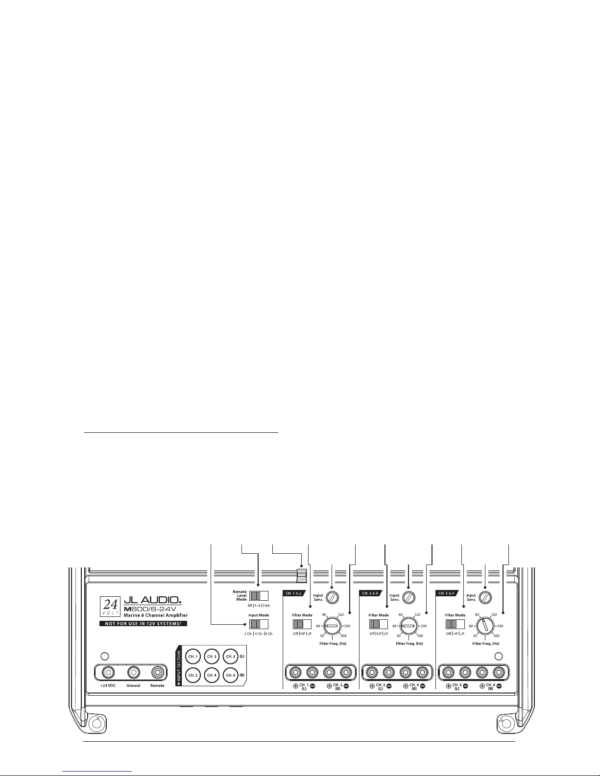
Status
LED
(pg. 11)
Ch. 1 & 2 Filter
Frequency
Selector
(pg. 8)
Ch. 1 & 2
Filter Mode
Selection
(pg. 8)
Ch. 1 & 2 Input
Sensitivity Control
(pg. 7)
Remote
Level Mode
Switch
(pg. 9)
Input
Mode
Switch
(pg. 7)
Ch. 3 & 4 Filter
Frequency
Selector
(pg. 8)
Ch. 3 & 4
Filter Mode
Selection
(pg. 8)
Ch. 3 & 4 Input
Sensitivity Control
(pg. 7)
Ch. 5 & 6 Filter
Frequency
Selector
(pg. 8)
Ch. 5 & 6
Filter Mode
Selection
(pg. 8)
Ch. 5 & 6 Input
Sensitivity Control
(pg. 7)
3
PLANNING YOUR INSTALLATION
It is important that you take the time to read
this manual and that you plan out your
installation carefully. The following are some
considerations that you must take into account
when planning your installation.
Cooling Efficiency Considerations:
The outer shell of your JL Audio amplifier
is designed to remove heat from the amplifier
circuitry. For optimum cooling performance,
this outer shell should be exposed to as large a
volume of air as possible. Enclosing the amplifier
in a small, poorly ventilated chamber can
lead to excessive heat build-up and degraded
performance. If an installation calls for an
enclosure around the amplifier, we recommend
that this enclosure be ventilated with the aid
of a fan. In normal applications, fan-cooling
is not necessary.
Mounting the amplifier upside down is
strongly discouraged.
Safety Considerations:
Your amplifier needs to be installed in a dry,
well-ventilated environment and in a manner
which does not interfere with your vehicle or
vessel’s factory installed electronic devices. You
should also take the time to securely mount the
amplifier using appropriate hardware so that it
does not come loose in the event of a collision or a
sudden jolt to the vehicle or vessel.
Stupid Mistakes to Avoid:
• Check before drilling any holes in your vehicle
or vessel to make sure that you will not be
drilling through the hull, a fuel tank, fuel line,
wiring harness or other vital system.
• Do not run system wiring outside or underneath
the vehicle or vessel. This is an extremely
dangerous practice which can result in severe
damage and/or injury.
• Protect all system wires from sharp edges
(metal, fiberglass, etc.) by carefully routing
them, tying them down and using grommets
and loom where appropriate.
• Do not mount the amplifier in the engine
compartment or in any other area that will
expose the amplifier circuitry to the elements.
While this amplifier is designed
for marine applications, it is not waterproof
and it should not be mounted where it is
likely to get wet.
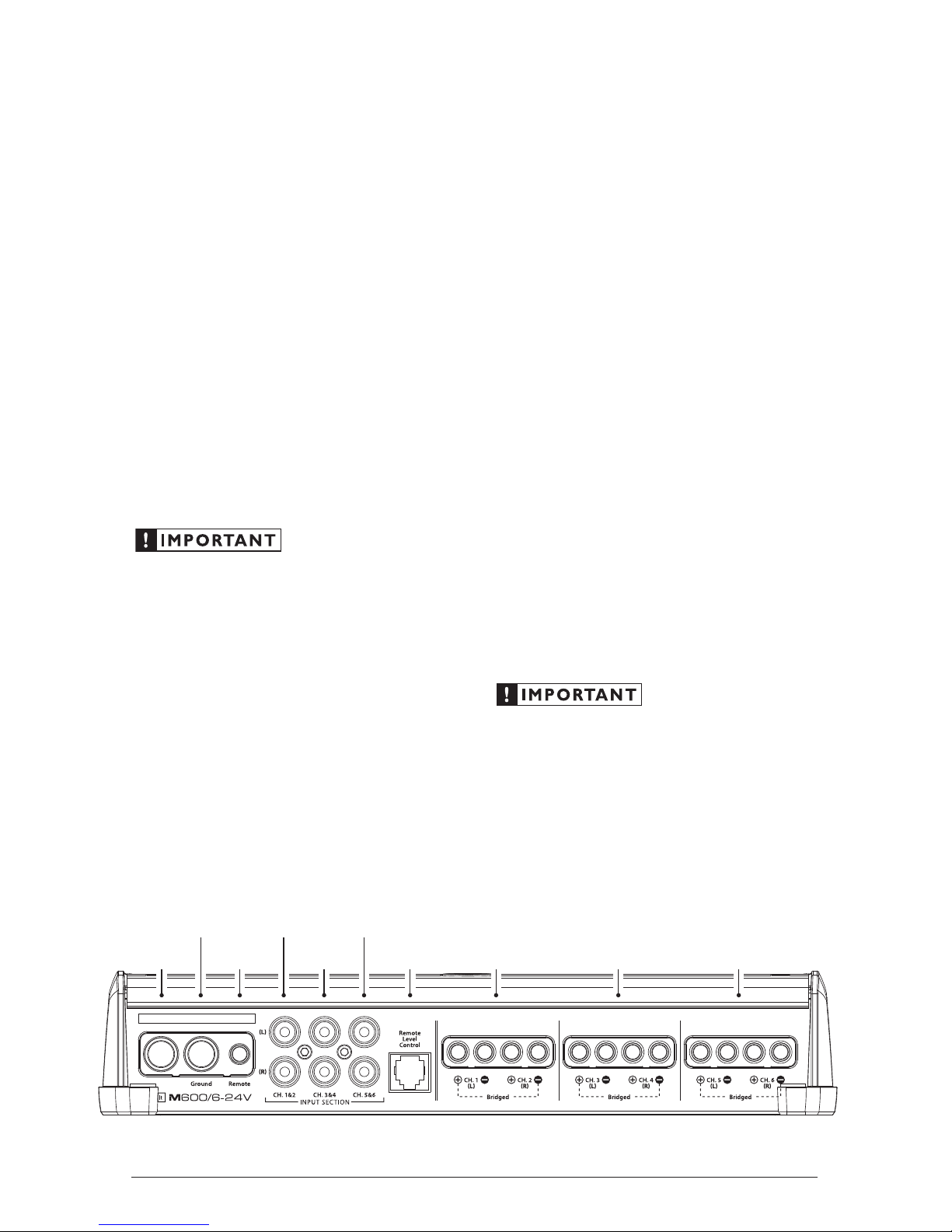
Ground Remote+24 VDC
NOT FOR USE IN 12V SYSTEMS!
Remote Turn-On
Connector
(pg. 6)
Chassis Ground
Connector
(pg. 5)
Channels 1 & 2
Preamp Input Jacks
(pg. 7)
Channels 5 & 6
Preamp Input Jacks
(pg. 7)
+24 V Power
Connector
(pg. 5)
Channels 5 & 6
Speaker Outputs
(pg. 10)
Channels 3 & 4
Speaker Outputs
(pg. 10)
Channels 1 & 2
Speaker Outputs
(pg. 10)
Jack for
Remote Level
Control Knob
(pg. 9)
Channels 3 & 4
Preamp Input Jacks
(pg. 7)

4 | JL Audio - M600/6-24V Owner’s Manual
PRODUCT DESCRIPTION
The JL Audio M600/6-24V is a six-channel,
full-range audio amplifier utilizing JL Audio
NexD™ ultra-high speed switching technology to
deliver outstanding fidelity and efficiency.
The M600/6-24V can be operated with a wide
variety of source units and system configurations.
TYPICAL INSTALLATION SEQUENCE
The following represents the sequence
for a typical amplifier installation in a
vessel, using an aftermarket source unit.
Additional steps and different procedures
may be required in some applications. If
you have any questions, please contact your
authorized JL Audio dealer for assistance.
1) Disconnect the negative battery post
connection and secure the disconnected cable
to prevent accidental re-connection during
installation. This step is not optional.
2) Run 8 AWG power wire from the battery
location to the amplifier mounting location,
taking care to route it in such a way that it
will not be damaged and will not interfere
with vehicle or vessel operation. Use 4 AWG
or larger power wire and a power distribution
block if additional amplifiers are being
installed with the M600/6-24V.
3) Connect power wire to the positive battery
post. Fuse the wire with an appropriate fuse
block or circuit breaker (and connectors)
within 18 inches (45 cm) wire length of the
positive battery post. This fuse/circuit breaker
is essential to protect the vessel/vehicle. Do
not install the fuse until the power wire has
been securely connected to the amplifier.
4) Connect negative power wire to the negative
battery post. Use the same size power
wire as the wire connected to the “+24V”
connection (minimum 8 AWG).
5) Run signal cables and remote turn-on wire
from the source unit to the amplifier
mounting location.
6) Run speaker cable from the speaker systems
to the amplifier mounting location.
7) Securely mount the amplifier.
8) Connect the positive and negative power
wires to the amplifier. A fuse near
the amplifier is not necessary if the
M600/6-24V is the only device being
run from the fused main power wire. If
the fused main power wire is shared by
the M600/6-24V and other amplifiers
or devices, fuse each amplifier/device
within 12 inches (30 cm) of wire length,
via a fused distribution block or multiple
individual fuse blocks/on-board fuses.
9) Connect the remote turn-on wire
to the amplifier.
10) Connect the input cables to the amplifier.
11) Connect the speaker cables to the amplifier.
12) Carefully review the amplifier’s control
settings to make sure that they are set
according to the needs of the system.
13) Install the power wire fuse or circuit breaker
(30A for a single M600/6-24V) and reconnect
the negative battery post terminal. Install
a fuse or circuit breaker (30A) near the
amplifier in multiple amp systems sharing a
main power wire.
14) Turn on the source unit at a low level
to double-check that the amplifier is
configured correctly. Resist the temptation
to crank it up until you have verified the
control settings.
15) Make necessary adjustments to the input
sensitivity controls to obtain the right
overall output and the desired balance
in the system. See Appendix A (page 14)
for the recommended input sensitivity
setting method.
16) Enjoy the fruits of your labor with your
favorite music.
5
POWER CONNECTIONS
Before installing the amplifier, disconnect the
negative (ground) wire from the vehicle/vessel’s
battery. This will prevent accidental damage to
the system, vehicle/vessel and your body during
installation.
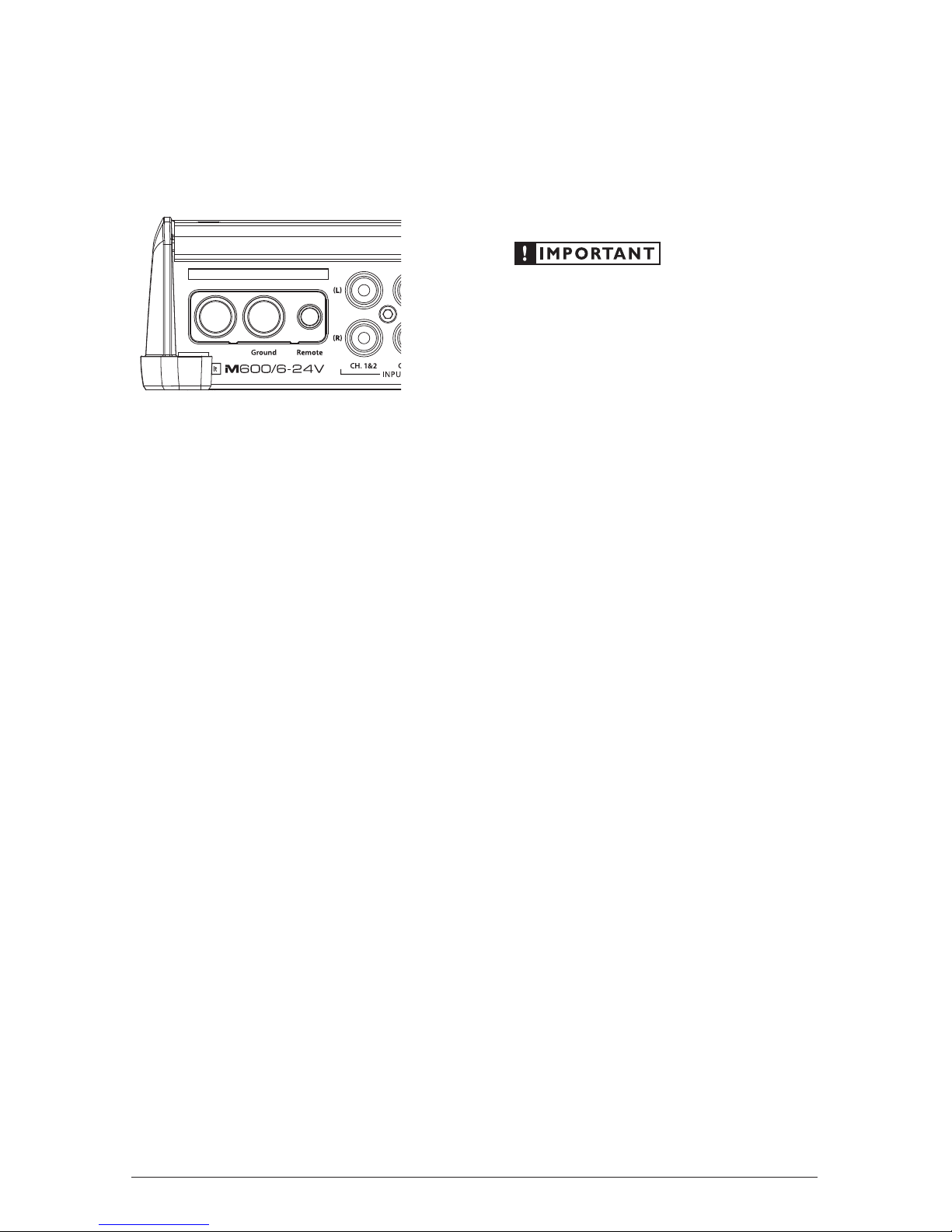
Ground Remote+24 VDC
NOT FOR USE IN 12V SYSTEMS!
The M600/6-24V’s “+24 VDC” and “Ground”
connections are designed to accept up to 4 AWG
power wire. 8 AWG is the required wire size for
this amplifier.
If you are installing the M600/6-24V with
other amplifiers and wish to use a single main
power wire, use 4 AWG, 2 AWG or 1/0 AWG
main power wire (depending on the overall
current demands of all the amplifiers in the
system). This 4, 2 or 1/0 AWG power wire should
terminate into a fused distribution block mounted
as close to the amplifiers as possible (within 12
inches / 30cm of wire length). The fused output
of the distribution block will connect to the
M600/6-24V with 8 AWG power wire. JL Audio
ECS fused distribution blocks are recommended
(XD-FDBU-2 and XD-FDBU-4)
Note: Smaller AWG numbers mean bigger
wire and vice-versa (1/0 AWG is the largest, 2
AWG is smaller, then 4 AWG, then 8 AWG, etc.).
To connect the power wires to the amplifier,
first back out the set screw on the top of the
terminal block, using the supplied 2.5 mm hex
wrench. Strip 1/2 inch (12 mm) of insulation from
the end of each wire and insert the bare wire into
the terminal block, seating it firmly so that no
bare wire is exposed. While holding the wire in
place, tighten the set screw firmly, taking care not
to strip the head of the screw.
The ground connection should be made using
the same gauge wire as the power connection.
Any wires run through barriers must
be protected with a high quality rubber
grommet to prevent damage to the
insulation of the wire. Failure to do so
may result in a dangerous short circuit.
Many vehicles/vessels employ small (10 AWG 6 AWG) wire to connect the alternator’s
positive connection to the battery and ground
connection to the chassis or battery. To prevent
voltage drops, these wires should be upgraded,
where possible, to 4 AWG when installing
amplifier systems with main fuse ratings above
60A.
FUSE/CIRCUIT BREAKER REQUIREMENTS
It is absolutely vital that the main power
wire(s) to the amplifier(s) in the system be
fused within 18 inches (45 cm) of the positive
battery post connection. The fuse value at each
power wire should be high enough for all of the
equipment being run from that power wire. If
only the M600/6-24V is being run from that
power wire, we recommend a 30A fuse or circuit
breaker be used.
If fusing the amplifier near its power
connections (when more than one amp is being
run from the main power wire), use a 30A fuse.
MAXI™ (big plastic-body) fuses or JL Audio
marine-grade circuit breakers are recommended.

6 | JL Audio - M600/6-24V Owner’s Manual
TURNON LEAD
The M600/6-24V uses a conventional +12 to
24V remote turn-on lead, typically controlled
by the source unit’s remote turn-on output. The
amplifier will turn on when any voltage between
+12V and +24V is present at its “Remote” input
and turn off when this voltage is switched off. If
a source unit does not have a dedicated remote
turn-on output, the amplifier’s turn-on lead can
be connected to +12V to +24V via a switch that
derives power from an ignition-switched circuit.
Ground Remote+24 VDC
NOT FOR USE IN 12V SYSTEMS!
The M600/6-24V’s “Remote” turn-on
connector is designed to accept 18 AWG – 12
AWG wire. To connect the remote turn-on
wire to the amplifier, first back out the set
screw on the top of the terminal block, using
the supplied 2.5mm hex wrench. Strip 1/2
inch (12mm) of wire and insert the bare wire
into the terminal block, seating it firmly so
that no bare wire is exposed. While holding
the wire in the terminal, tighten the set screw
firmly, taking care not to strip the head of the
screw and making sure that the wire (not the
insulation) is firmly gripped by the set screw.
 Loading...