

Page 1
OWNER’S MANUAL
Marine Subwoofer with
Built-In RGB LED Lighting (optional)
Thank you for choosing a JL Audio Marine Subwoofer.
With proper installation, your new speaker will deliver
years of listening pleasure.
We strongly recommend that you have your subwoofer
installed by your authorized JL Audio dealer.
The installation professionals employed by your dealer have
the necessary tools and experience to properly install this product.
If you prefer to perform your own installation,
please read this instruction manual completely before
beginning the process.
Page 2
PHYSICAL SPECIFICATIONS
B
M3-10
10.0-INCH MARINE SUBWOOFER D RIVER
Built in USA with global componen ts.
Patents pending.
A
C
E
D
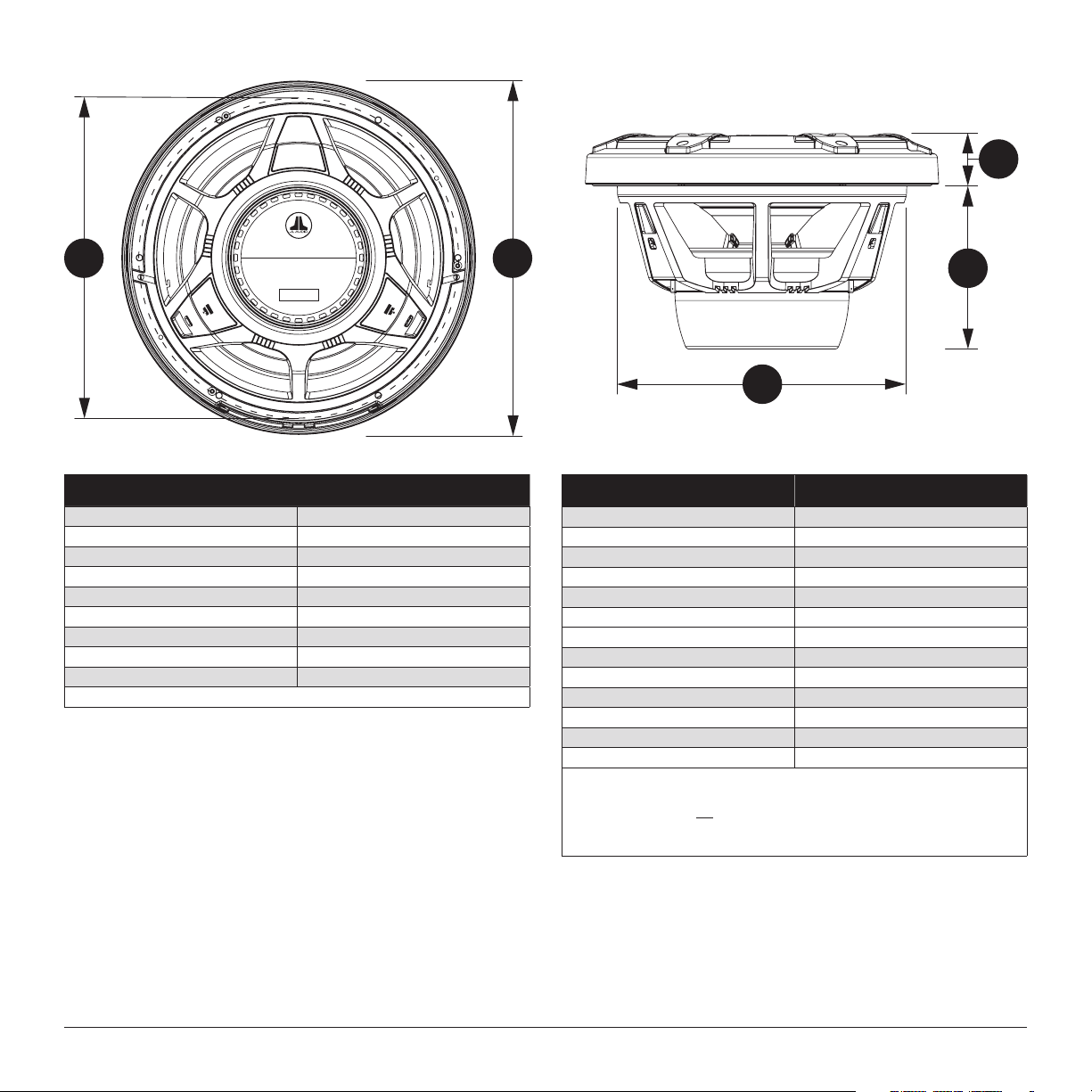
Subwoofer Physical Specifications
Nominal Diameter 10 in / 250 mm
Outer Diameter (A) 10.75 in / 273 mm
Bolt Hole Circle (B) 9.71 in / 247 mm
Frontal Grille Protrusion-Classic* (C) 1.50 in / 38 mm
Frontal Grille Protrusion-Sport* (C) 1.58 in / 40 mm
Mounting Hole Diameter (D) 8.875 in / 225 mm
Mounting Depth (E) 5.00 in / 127 mm
Net Weight 12.60 lbs / 5.70 kg
Driver Displacement 0.52 ft / 1.47 litres
* Frontal grille protrusion measured from mounting surface (Sport Grille Pictured)
INCLUDED PARTS
• One Polymer Subwoofer Grille
• Six #8 x 1 1/2-inch (38 mm) Phillips pan-head stainless-steel screws
• Six #8 stainless-steel washers
• Logo Badges
One Pair Black (Gunmetal Sport Models Only)
One Pair White (White Sport Models Only)
LED Equipped Models
Built-in, RGB LED lighting delivers beautiful accent illumination. LED functionality
requires separate wiring at each speaker location. Adjustable control of RGB
lighting requires the use of an RGB lighting controller (sold separately). For optimal
performance, we recommend using the JL Audio marine lighting controller (MLC-RW).
Subwoofer Parameters M3-10IB
Free Air Resonance (Fs): 41.84 Hz
Electrical “Q” (Qes): 0.806
Mechanical “Q” (Qms): 11.751
Total Speaker “Q” (Qts): 0.754
Equivalent Compliance (Vas): 1.29 ft
One-way, Linear Excursion (Xmax)*: 0.42 in / 10.7 mm
Efficiency (1W/1m)**: 87.23 dB SPL
Effective Piston Area (Sd): 50.68 in / 0.0327 m
DC Resistance (Re): 3.957 ohm
Nominal Impedance: 4 ohm
Infinite Baffle Use: Yes (Preferred)
Enclosure Use: Yes (Sealed Only)
Power Handling (continuous): 175W
* Xmax specifications are derived via one-way voice coil overhang method with no
correction factors applied.
** Efficiency (1W/1m) is not an accurate indicator of a subwoofer’s output capability
and should not be used as a comparison to other subwoofers to determine which
one is “louder” !
We recommend the use of this speaker in a bi-amplified system using high-quality satellite
speakers and amplifiers. We do not recommend the use of this subwoofer with a passive
crossover (coil), as this type of device will adversely affect performance.
3
/ 36.53 litres
2 JL AUDIO M 3 -10 I B
All specifications are subject to change without notice.
Page 3
While this speaker is designed to be water and spray resistant, it is not
designed to be submerged or to withstand high-pressure water spray. Do not
install on submersibles, personal watercraft or any other vessel likely to be
under water at any time.
Please exercise care when washing your boat to avoid damaging your
speaker. Avoid contact with harsh chemicals or cleaning agents to prevent
damage to the speaker’s finish that will not be covered under warranty. Wash
with mild soap and rinse with freshwater only.
Prolonged exposure to sound pressure levels in excess of 100dB can cause
permanent hearing loss. This high-performance speaker can exceed this level.
Please exercise restraint in its operation in order to preserve your ability to
enjoy its fidelity.
When installing a subwoofer in your vessel, it is extremely important to secure
it firmly. This applies not only to the woofer itself, but also any structure it
is mounted to. If not firmly attached, the speaker can become dangerous
projectile in a collision. Please review the mounting information carefully and
use the supplied marine-grade hardware to mount this product.
It is absolutely vital that your speaker is connected as shown in this manual.
Failure to connect the system as shown will result in damage to your speakers
which is NOT covered under warranty.
Do not attempt to remove the lighting LEDs from the grille. The LEDs are
permanently fixed to the grille and their wiring is permanently fixed and
attempting to remove them will cause damage and this damage will not be
covered under warranty.
JL AUDIO M 3 -10 I B 3
All specifications are subject to change without notice.
Page 4
ENCLOSURE SPECIFICATIONS
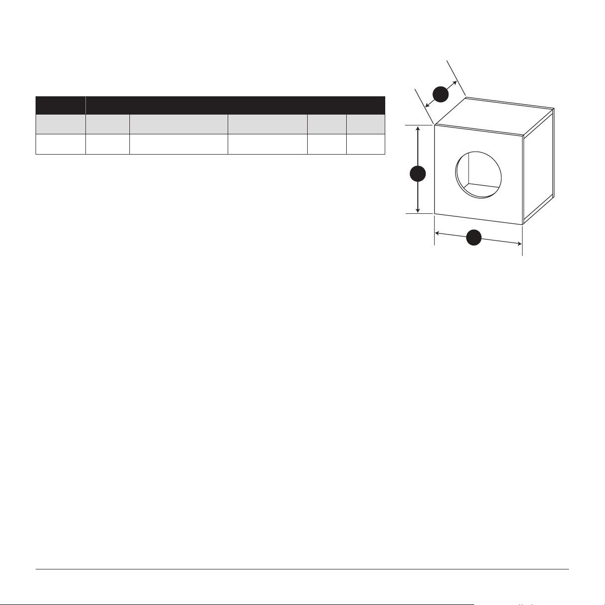
The M3-10IB subwoofer is designed for infinite-baffle operation with a large volume of air behind it
(at least 2 cu. ft. / 56.6 l). For best performance, the installation location/compartment must remain unoccupied
and free of boating equipment (safety gear, life jackets, etc.). If you decide to build a dedicated enclosure, you
may refer to the suggested design below.
Subwoofer Recommended Sealed Design
M3-10IB
Volume
(net int.)
2.00 ft
56.6 litres
External Dimensions
(Width x Height x Depth)
18 in. x 18 in. x 14.5 in.
457 mm x 457 x 368 mm
F3
(Hz)
Fc
(Hz)
Qtc
42.9 53.66 0.967
NOTE: The enclosure recommendations listed are external dimensions which assume the use of 3/4" (19mm)
thick material. If you are using 5/8" (16mm) thick material, subtract 1/4" (6.5mm) from each dimension. Do not use
any material with a thickness of less than 5/8" (16mm) as this may compromise the rigidity of the enclosure.
NOTE: All enclosure volumes listed are net internal volumes! Box volume displacement, port displacement and
brace displacement must be added to obtain the final gross internal volume. All enclosure dimensions listed have
already taken this into account.
Sealed Design
D
H
W
4 JL AUDIO M 3 -10 I B
All specifications are subject to change without notice.
Page 5
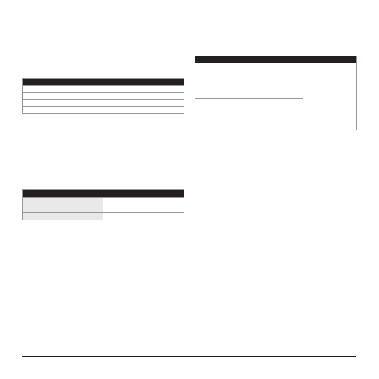
INTEGRATED RGB LED LIGHTING
Illuminated speaker models are outfitted with multi-color LEDs to produce vibrant
accent lighting. Embedded within each speaker grille are six RGB LEDs, positioned and
concealed from direct sight. Wire leads exiting from behind the grille includes LED
connections. Refer to the table below for individual RGB wire connection info.
Note: Wiring connections at each speaker location are required for
LED functionality.
Wire Color RGB LED Connection
Red Red RGB LED Negative (–)
Green Green RGB LED Negative (–)
Blue Blue RGB LED Negative (–)
Yello w Main RGB LED Positive (+12V)
Adjustable control of RGB lighting may be achieved with the use of an RGB lighting
controller (sold separately). Refer to the instructions of your RGB lighting controller for
specific connection info. Note: When selecting an RGB lighting controller, make
sure that the total amperage demands of all LED circuits does not exceed the
output capacity of the controller. Refer to the table below for the individual
current draw amounts and sum (add) the total. For optimal performance, we
recommend using the JL Audio marine lighting controller (MLC-RW).
RGB LED SPECIFICATIONS
Specification M3 -10IB
LED Curre nt Draw at 12V DC 108 mA
Recommended Fuse Value 15 0 mA
LED Voltage Range 10 - 14.4V DC
DIRECT LED WIRING
Alternatively, you may hard wire individual leads or a combination of leads to achieve
up to seven different LED color assortments. Refer to the table below for the wire colors
used to achieve specific LED colors.
LED Color Wire Color(s) Connection
Red Red
Green Green
Blue Blue
Yello w Red and Green
Pink Red and Blue
Aqua Green and Blue
White Red, Green and Blue
Combine all YELLOW (+12V ) leads together (parallel) and connect to a switched +12V
supply. See below for additional info.
Combine selected wires
from all speakers and
connect to negative
ground or to the negative
(–) battery post.
LED WIRING CONSIDERATIONS
• Do not connect to 24V electrical systems.
• Do not connect the speakers’ LED lights to the vessel’s navigational
lighting circuits.
• For short-circuit protection, we recommend installing a fuse (not included) at
EACH speaker’s YELLOW (+12V) LED power connection lead. Refer to the
RGB LED Specifications table (at left) for recommended fuse ratings.
• We recommend a minimum of 16AWG wire size for each speaker’s LED
connection circuits.
• In addition to the above, we recommend activating the speakers’ LEDs thru
a cabin/interior lighting circuit that supplies +12V via an existing switch. If an
existing switched circuit is not available, you may install a dedicated toggle/
rocker style switch that will supply positive (+12V) power. Fuse this main +12V
connection according to the total amperage demands of all LED circuits.
Refer to the RGB LED Specifications table (at left) for individual current draw
amounts and recommended fuse ratings.
JL AUDIO M 3 -10 I B 5
All specifications are subject to change without notice.
Page 6
BEFORE YOU BEGIN INSTALLING
M3-10
10.0-INCH MARINE SUBWOO FER DRIVER
Built in USA with global components.
Patents pending.
• Check with your local waterway authority for any regulations regarding the use
of accent/speaker lighting on your vessel.
• Turn off the audio system. It is also advisable to disconnect your battery system
whenever performing installation work.
• Before cutting, drilling or inserting any screw, check clearances on both sides of
the planned mounting surface. Also check for any potential obstacles, such as
wiring harnesses, fuel lines, hydraulic lines, etc. Check both sides of the vessel
before cutting any holes.
• If you are running cables through bulkheads, drill holes for the cable and use a
urethane or plastic grommet to protect the wire from chafing in the hole. Make
sure that the cables will clear any mechanical devices in the boat and secure
them with wire ties.
• Wear protective eyewear at all times and a dust mask and gloves when drilling
or cutting.
INSTALLATION PROCEDURE
Diagrams A & B (page 7) shows typical installation procedures into a fiberglass
panel, using the supplied hardware. Always follow proper safety procedures. Use
eye-protection at all times and a dust mask and gloves when cutting.
1) Choose a flat mounting surface that has sufficient depth and air space
behind it to accept the subwoofer.
2) Using a hole saw or jigsaw, cut a 8.875-inch (225 mm) diameter hole.
3) Route the speaker cable to the mounting location. For LED equipped
models, now is also a good time to run wires to the speaker location for
LED activation.
4) Place the woofer in the hole and mark the screw hole locations using a
sharp, pointed tool.
5) Remove the woofer and drill a pilot hole (see the Pilot Hole
Recommendations chart at the right) in each of the screw locations. It
is also advisable to use a hand-driven countersink tool on each hole to
further inhibit gel-coat cracking of fiberglass panels.
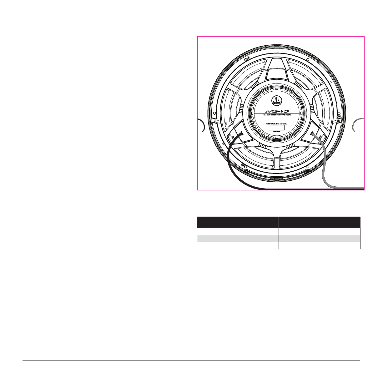
6) Connect the speaker wires from the amplifier to the woofer connections
(see Speaker Connections at right).
7) If equipped, connect the LED circuit leads (see page 5).
8) Place the woofer, with its grille in place, into the opening and while
holding the speaker firmly in its mounting location, evenly snug the
mounting screws in a criss-cross pattern, then hand tighten in a
criss-cross pattern.
SPEAKER CONNECTIONS
Yellow & Red RG B
LED connection leads
(LED mode ls only)
#8 SCREW: PILOT HOLE RECOMMENDATIONS
Fiberglass Thickness Recommended Pilot Hole Drill Size
0.125 in. (3.18 mm) or less 7/64 in. (2.78 mm) pilot hole
foam core / fiberglass sandwich 7/64 in. (2.78 mm) pilot hole
larger than 0.125 in (3.18 mm) 1/8 in. (3.18 mm) pilot hole
Blue & Gre en RGB
LED connection leads
(LED mode ls only)
to amplier output
Non-standard installations may require different hardware. Always use
marine-grade, stainless-steel fasteners to ensure a secure, reliable installation.
6 JL AUDIO M 3 -10 I B
All specifications are subject to change without notice.
Page 7
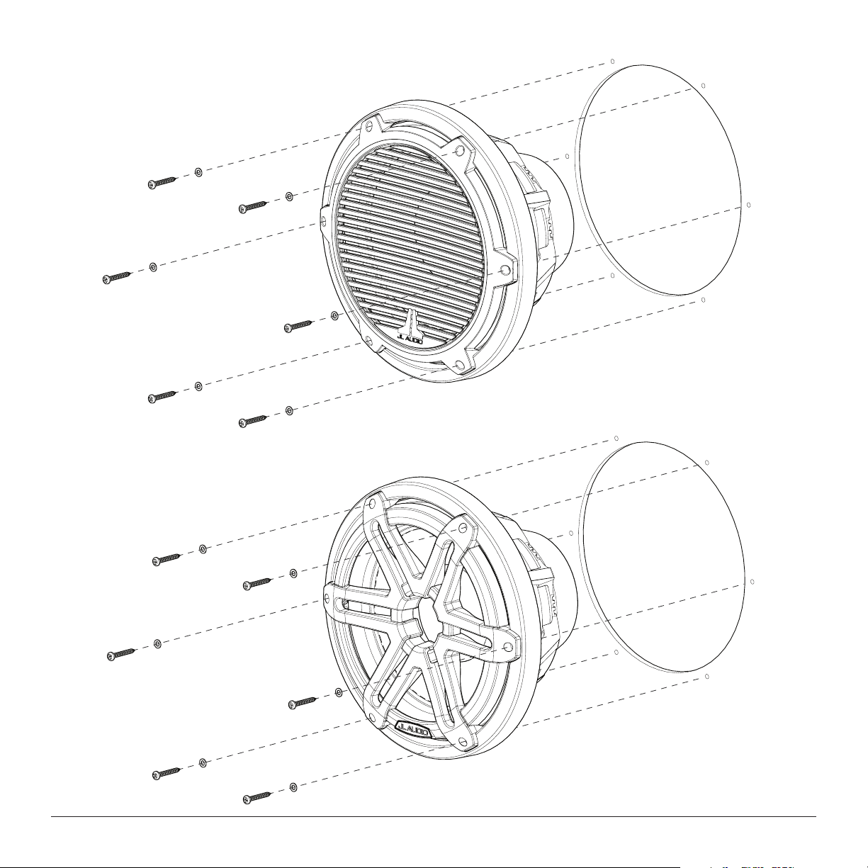
DIAGRAM A
Classic Grille Model Installation
DIAGRAM B
Sport Grille Model Installation
JL AUDIO M 3 -10 I B 7
All specifications are subject to change without notice.
Page 8
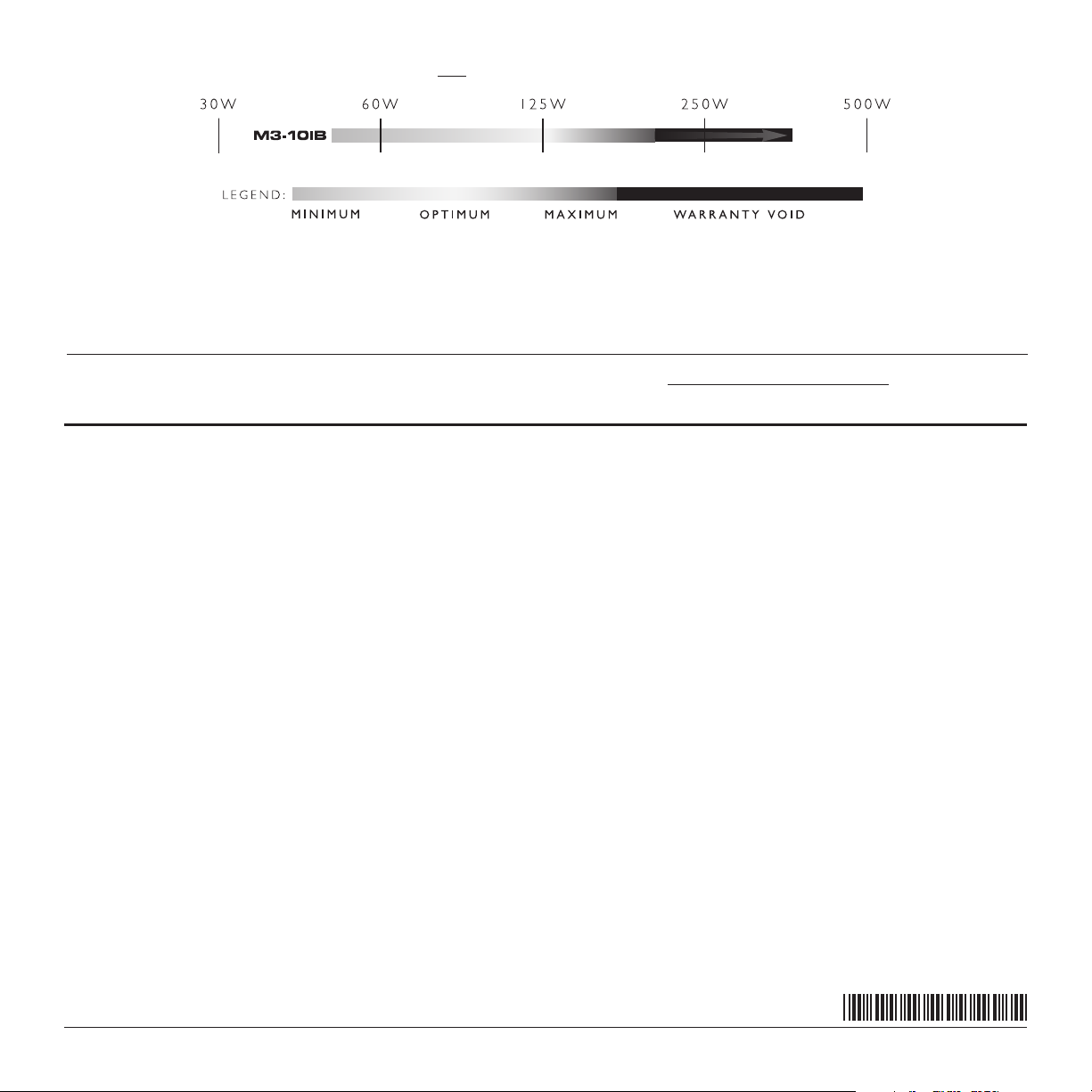
RECOMMENDED CONTINUOUS RMS POWER RANGE FOR ONE SUBWOOFER DRIVER:
MEDIUM G RAY MINIMU M:
From a reliability standpoint, this zone
represe nts a ver y comfor table op erating power
range for each drive r. This level of power will not
stress th e woofer but will not e xtrac t all of its
performance potential, either.
Use of less th an the minimum power level
will not damage the wo ofer, but may re sult in
unsatisfactory performance.
When designing systems with our drivers, it is very important to achieve a good power match between the subwoofer amplifier and the subwoofer driver's capabilities. The power levels listed in the above
chart represent continuous (RMS) amplifier power per woofer and assume that the user will regularly make full use of that power without drastically overdriving the amplifier(s). Make sure you factor system
impedance and the total number of subwoofers into your calculations. Adhering to these power recommendations will result in systems that are both reliable and enjoyable.
LIGHT GRAY OPTIMUM:
This zone represents the best compromise
between long-term reliability, high-output and
low-distort ion per forman ce. This po wer level is
lower than the woofer’s continuous power rating
(as publish ed in its sp ecifi cations), bu t you will st ill
be taking advantage of the woofer’s, low-distortion
perfo rmance range wit hout undue risk of f ailure.
DARK G RAY MAXIMUM:
Slightly m ore SPL will b e gained by pushing th e
power into this zone, bu t typically not m ore than
2dB, compa red to the ligh t gray zone. Th e subwoofe r
driver is d esigned to opera te safely up to this p ower
range, but not beyond. Operate with caution.
BLACK WARR ANTY VOI D:
We do not recommend operating wo ofers at
this level o f power. In this z one, ther e is a very
high prob abilit y that the dr iver will f ail due to
excessive heat and/or mechanical stress.
Subwoofer drivers ope rated at t hese levels of
power are NOT covered under warranty.
JL AUDIO LIMITED WARRANTY USA
Marine Subwoofer Components
JL AUDIO warrants this speaker to be free of defects in materials and
workmanship for a period of two (2) years from the original date of purchase.
This warranty is not transferable and applies only to the original
purchaser of the product from an authorized JL AUDIO dealer. Warranty is
voided if the factory-applied product serial number is removed or defaced.
Damage caused by the following is not covered under warranty: accident,
misuse, abuse, product modification or neglect, failure to follow installation
instructions, unauthorized repair attempts, misrepresentations by the seller. This
warranty does not cover incidental or consequential damages and does not cover
the cost of removing or reinstalling the unit(s). Cosmetic damage due to accident
or normal wear and tear is not covered under warranty.
Should service be necessary under this warranty for any reason due to
manufacturing defect or malfunction, JL AUDIO will, at its discretion, repair or
replace the defective product with new or remanufactured product at no charge.
Products installed as original equipment by boat manufacturers are covered by
the boat manufacturer’s warranty, not JL Audio, Inc.
Any applicable implied warranties are limited in duration to the period of
the express warranty as provided herein beginning with the date of the original
purchase at retail, and no warranties, whether express or implied, shall apply to
this product thereafter. Some states do not allow limitations on implied warranties,
therefore these exclusions may not apply to you. This warranty gives you specific
legal rights, and you may also have other rights which vary from state to state.
If you need service on your JL AUDIO product:
All warranty returns should be sent to JL AUDIO freight prepaid through an
authorized JL AUDIO dealer and must be accompanied by proof of purchase
(a copy of the original sales receipt.) Direct returns from consumers or nonauthorized dealers will be refused unless specifically authorized by JL AUDIO with
a valid return authorization number. Warranty expiration on products returned
without proof of purchase will be determined from the manufacturing date code.
Coverage may be invalidated as this date is previous to purchase date. Return only
defective components. Non-defective items received will be returned freightcollect. Customer is responsible for shipping charges and insurance in sending the
product to JL AUDIO. Freight damage on returns is not covered under warranty.
Always include proof of purchase (sales receipt).
JL Audio customer service: (954) 443-1100 during normal business hours (Eastern Time)
For Service Information in the U.S.A. please call:
JL Audio, Inc
10369 North Commerce Parkway, Miramar, FL 33025
International Warranties:
Products purchased outside the United States of America are covered only by that country’s distributor and not by JL Audio, Inc.
Printed in U.S.A. M3-10IB_052919_SKU#011515
 Loading...