

JL Audio M1700 Owner's Manual
Thank you for purchasing a JL Audio amplifier for
your marine sound system.
Your amplifier has been designed and manufactured to exacting
standards in order to ensure years of musical enjoyment in your vehicle.
For maximum performance, we highly recommend that you have
your new amplifier installed by an authorized JL Audio dealer. Your
authorized dealer has the training, expertise and installation equipment
to ensure optimum performance from this product. Should you
decide to install the amplifier yourself, please take the time
to read this manual thoroughly so as to familiarize yourself
with its installation requirements and setup procedures.
If you have any questions regarding the instructions in this
manual or any aspect of your amplifier’s operation, please contact your
authorized JL Audio dealer for assistance. If you need further assistance,
please call the JL Audio Technical Support Department
at (954) 443-1100 during business hours.
OWNER’S MANUAL
PLANNING YOUR INSTALLATION
It is important that you take the time to read
this m anual and t hat you plan out your
insta llation caref ully. The followi ng are some
considerat ions that you must t ake into account
when plan ning your ins tallation.
Cooling Efficiency Consid erations:
The outer shell of your JL Audio amplifier
is designed to remove heat from the amplifier
circuit ry. For optimum co oling performa nce,
this outer shell should be exposed to as large a
volume of air as possible. Enclosing the amplifier
in a small, poorly ventilated chamber can
lead to excessive heat build-up and degraded
performance. If an installation calls for an
enclosure around the amplifier, we recommend
that t his enclosure be ventilated with the aid
of a fan. In normal applications, fan-cooling
is not nece ssary.
Mounting t he amplifier upsi de down is
strongly discouraged.
If mounting the amplifier under a seat,
make su re there is at lea st 1 inch (2.5 c m) of
space above the amplif ier’s outer shel l to permit
proper coolin g.
Safety Considerations:
Your amplifier needs to be installed in a dry,
well-ventilat ed environment a nd in a manner
which does not interfere with your vessel’s factory
installed electronic devices. You should also take
the time to securely mount the amplifier so that it
does not come loose in the event of a collision or a
sudden jolt to the vessel.
Stupid Mistakes to Avoid:
• Check before drilling any holes in your vessel to
make sure that you will not be drilling through
the hull, a fuel tank, fuel line, wiring harness or
other v ital vessel sy stem.
• Do not run system wiring outside or underneath
the vessel. This is an extremely dangerous
practice which can result in severe damage to
your vess el and person.
• Protec t all system wires from sh arp edges
(metal, fiberglass, etc.) by carefully routing
them, tying them down and using grommets
and loom w here appropriate.
• Do not mount the amplifier in the engine
compartment or in any other area that will
expose the amplifier circuitry to the elements.
While this amplifier is specially designed
for marine applications, it is not waterproof
and it should not be mounted where it is
likely to get wet.
PROTECT YOUR H EARING!
We value you as a long-term customer. For
that rea son, we urge you to pr actice restra int in
the oper ation of this produc t so as not to d amage
your hearing and that of others in your vessel.
Studies have shown that cont inuous exposure to
high sound pressure levels can lead to permanent
(irrepara ble) hearing loss . This and a ll other
high-power a mplifiers ar e capable of producing
such hig h sound pressure le vels when connect ed
to a spea ker system. Plea se limit your continuous
exposu re to high volume le vels.
While driving, operate your audio system in
a manner that still allows you to hear necessa ry
noises to operate your vessel s afely (horns ,
sirens, etc.).
SERIAL NUMBER
In the event that your amplifier requires
service or is ever stolen, you will need to have
a record of the product’s serial number. Please
take the time to enter that number in the space
provided be low. The serial nu mber can be fou nd
on the bottom panel of the amplifier and on the
amplifier packag ing.
Serial Number:
INSTALLATION APPLICATIONS
This amplifier is designed for operation in
vessels w ith 12 volt, negat ive-ground elect rical
systems . Use of this produc t in vessels w ith
positive ground and/or voltages other than 12V
may result in damage to the product and will void
th e w arr ant y.
This product is not certified or approved for
use in aircraf t.
Do not att empt to “bridge” t he outputs of th is
amplif ier with the outputs of a second amplifier,
includin g an identical one.
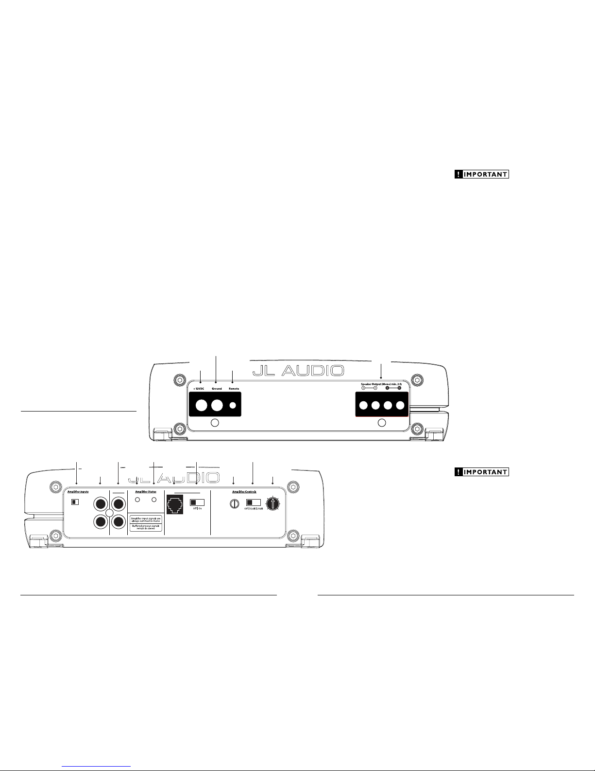
Bass Boost Controls
Input Voltage
Low | High
CH 1 (Left)
Input Sens. LP Filter
Filter Freq. (Hz)
40
45
55
65
80
100
200
Bass Boost
Remote
Bass Port
PowerProtect
CH 2 (Right)
Pre-Outs
Left & Right
Preamp Input J acks
(pg. 6)
Protection St atus
Indicator
(pg. 9)
Left & Right
Preamp Output Jacks
(pg. 8)
Input Voltage
Selection
(pg. 6)
Power Status
Indicator
(pg. 9)
Bass EQ
On/Off Switch
(pg. 8)
Jack for
Remote Bass
Control Knob
(pg. 8)
Filter Mod e
Selection
(pg. 7)
Filter
Frequency Selector
(pg. 7)
Input Sensitivity
Control
(pg. 6)
Remote Turn-On
Connector
(pg. 6)
Chassis Ground
Connector
(pg. 5)
+12 V Power
Connector
(pg. 5)
Speaker Outputs
(pg. 8)
2 JL AUDIO M1700 JL AUDIO M1700 3

POWER CONNECTIONS
Before installing the amplifier, disconnect the
negative (g round) wire f rom the vessel ’s batter y.
This will prevent accidental damage to the system,
the vess el and your bod y during inst allation.
The M1700 ’s “+12 V DC ” and “Grou nd”
connect ions are designed to accept 4 AWG power
wire. 4 AWG is a minimum power wire size for
this a mplifier.
If you are installing the M1700 with other
amplif iers and wish to use a single main power
wire, use 4 AWG or larger main power wire
(depending on the overall current demands of all
the amplifiers in the system). This 4 AWG or
larger power wire should terminate into a
distribution block mounted as close to the
amplifiers as possible and should connect to the
M1700 with 4 AWG power wire.
Note: Smaller AWG numbers mean bigger wire
and vice-versa (1/0 AWG is the largest, 2 AWG is
smaller, then 4 AWG, then 8 AWG, etc.).
To connect the power wires to the amplifier,
first back out the set screw on the top of the
terminal block, using the supplied 2.5 mm hex
wrench. S trip 1/2 inch (12 mm) of in sulation from
the end of each wire and insert the bare wire into
the terminal block, seating it firmly so that no
bare wire is exposed. While holding the wire in
place, tighten the set screw firmly, taking care not
to strip the head of the screw.
The ground connection should be made using
the sa me gauge wire as the power connect ion.
Any wires run through barriers must be
protected with a high quality rubber g rommet
to prevent damage to the insulation of the wire.
Failure to do so may result in a dangerous short
circuit.
Many vessels employ small (10 AWG - 6 AWG)
wire to connect the alternator’s positive
connection to the battery. To prevent voltage
drops, this wire should be upgraded to 4 AWG
when installing a mplifier systems with mai n
fuse rat ings above 60A.
It is common for the alternator to be grounded
through its chassis. If the alternator is not
grounded through its c hassis and in stead employs
a smal l (10 AWG - 6 AWG) wire to con nect to
ground, this wire should also be upgraded to 4
AWG when installing amplifier systems with main
fuse r atings above 60A .
FUSE REQUIREMENTS
It is absolutely vital that the main power
wire(s) to the amplifier(s) in the system be
fused within 18 inche s (45 cm) of t he positive
battery post connection. The fuse value at each
power wire should be high enough for all of the
equipment being run from that power wire. If
only the M1700 is be ing run from that power
wire, we recommend a 50A fuse be used. AFS
(small blad e fuse) or Maxi Fuse™ (big plast ic-body
fuse) ty pes are recom mended.
No fuse is required or rec ommended direct ly
before the amplifier power connection. If one is
desired, we recommend the use of a 50A AFS or
MaxiFu se™ type.
PRODUCT DESCRIPTION
The JL Audio M1700 is a monoblock
subwoofer amplifier utilizing proprietary and
patented Class D technology. Its frequency
response i s limited to t he range below 250 Hz. It
is not designed for driving midrange speakers or
tweeters. Every aspect of its operation has been
optimized for low-frequency amplification.
For detai led specific ations, please re fer to
Appendix C (page 13).
TYPICAL INSTALLATION SEQUENCE
The following represents the sequence for a
typical amplifier installation, using an aftermarket
source u nit. Additiona l steps and di fferent
procedures may be required i n some applications .
If you have any questions, please contact your
authoriz ed JL Audio deale r for assistance .
1) Disconne ct the negative battery post
connect ion and secure t he disconnec ted cable
to prevent accidental re-connection during
installation. This step is not optional!
2) Ru n positive and negat ive power wire
(minimum 4 AWG) from f rom the battery
location to the amplifier mounting location,
taki ng care to route it in such a way that it
will not be damaged a nd will not interfere
with vessel operation. Use 4 AWG or larger
power wire and a power distribution block
if addit ional amplifiers are bei ng installed
with t he M1700.
3) Connect power wire to the positive batter y
post. Fuse the wire with an appropriate fuse
block (and connectors) with in 18 inches (45
cm) wire length of t he positive batter y post.
This f use is essentia l to protect the vessel.
Do not ins tall the fuse unti l the power wire
has been connected to the amplifier.
4) Connect negat ive power wire to t he negative
battery post. Use t he same size p ower
wire as the wire connected to the “+12V ”
connection (minimum 4 AWG).
5) Run signal cables and remote turn-on wi re
from the source unit to t he amplifier
mounting location.
6) Run speaker wire from the speaker system
to the a mplifier mounti ng location.
7) Sec urely mount the amplifier.
8) Connect the positive a nd negative power
wires to the amplifier. A fuse near the
amplif ier is not necess ary.
9) Con nect the remote t urn-on wire to
the ampl ifie r.
10) Con nect the input ca bles to the ampl ifier.
11) Connect t he speaker wires to the a mplifier.
12) Carefully review the amplifier’s control
setti ngs to make sure that they are set
according to the needs of the s ystem.
13) Install power wire fuse (50A for a single
M1700) and reconnect the negative
battery post term inal.
14) Turn on t he source unit at a low level
to double-check that t he amplifier is
config ured correctly. Resist the temptation
to cran k it up until you have verified the
control set tings.
15) Make necessary adjustments to the input
sensitiv ity controls to obtain the right
overall output and the desired bala nce in the
system. See Appendi x A (page 12)
for the rec ommended input sensitivity
setti ng method.
16) Enjoy the fruits of your labor with your
favorite music .
4 JL AUDIO M1700 JL AUDIO M1700 5
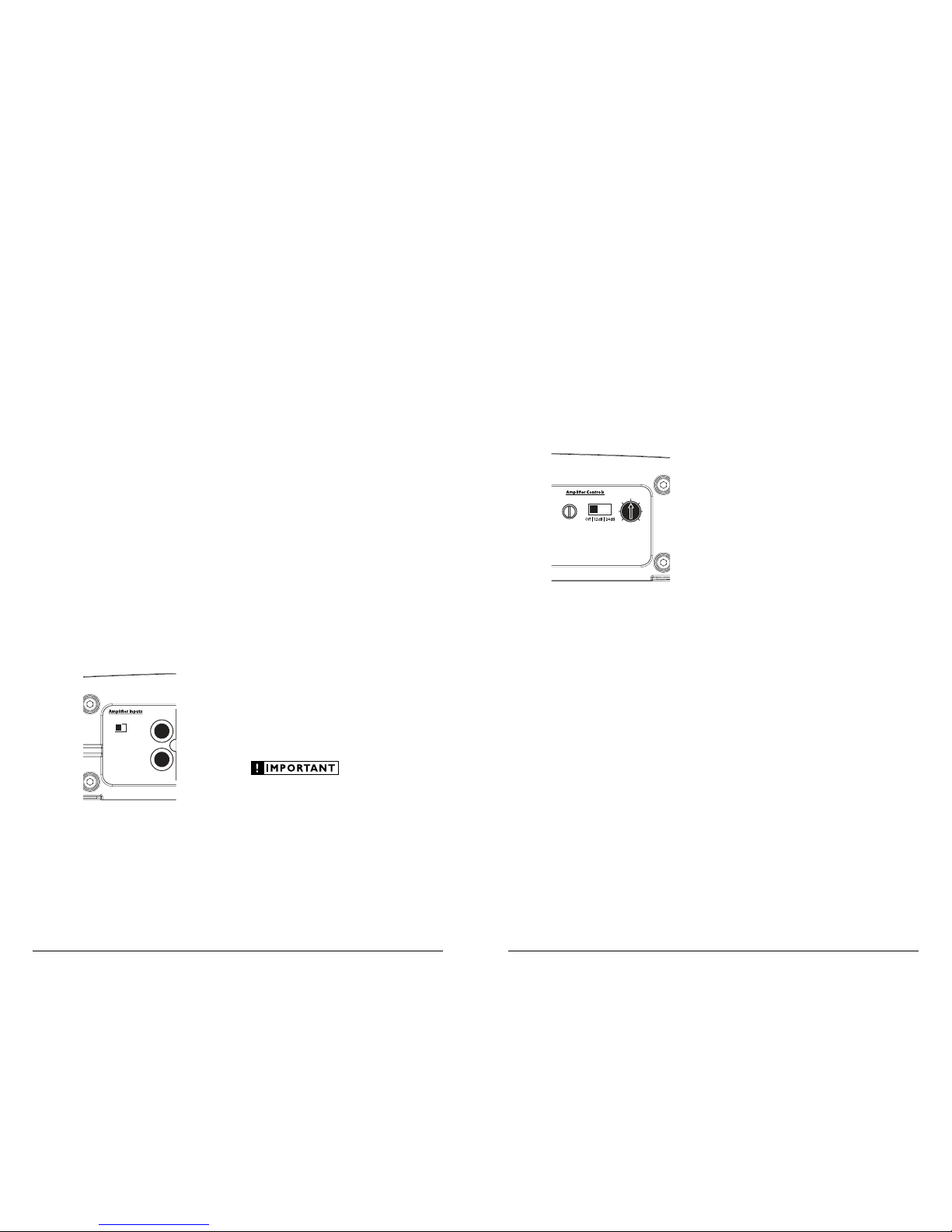
AMPLIFIER CONTROLS
1) “Input Sens .”: Once the appropriate “Input
Vol ta ge ” range has been selected, the control
labeled “Input Sens.” locate d in the “Amplifier
Controls ” section can be used to match the
source u nit’s output voltage to t he input
stage of the amplifier for maximum clean
output. Rot ating the control clockwise w ill
result in higher sensitivity (louder for a given
input voltage). Rotat ing the control counterclockwise will result in lower sensitivity
(quieter for a given input voltage.)
Input Sens. LP Filter
Filter Freq. (Hz)
40
45
556580
100
200
To properly set the amplifier for maximum
clean out put, please refer to Appendix A (page
12
) in this manual. After using this procedure,
you can then adjust any or all “Input Sens .”
levels dow nward i f this is requ ired to achieve
the desi red system bal ance.
Do not increase any “Input Sens.” setting
for any channel(s) of any amplifier in the
system beyond the maximum level established
during the procedure outlined in Appendix
A (page 12). Doing so will re sult in audible
distorti on and possible spe aker damage.
Filter Controls
Most spea kers are not desi gned to reproduce
the full range of frequencies audible by the
human e ar. For this reas on, most speaker
systems are comprised of multiple speakers, each
dedicated to reproducing a specific frequency
range. Fi lters are used to select which f requency
range is sent to each section of a speaker system.
The division of frequency ranges to different
speakers can be done with passive filters (coils
and/or capacitors between the amplifier outputs
and the speakers), which are acceptable and
commonly used for filter ing between m idrange speakers and tweeters. Filtering between
subwoofer systems and satellite speaker systems
is best done with active filters, which cut off
frequency content at the input to the amplifier.
Active filters are more stable than passive filters
and do not introduce extr aneous resista nce,
which ca n degrade subwoofer performance.
The active filter built into the M1700 can be
used to e liminate potent ially harm ful and/or
undesired frequencies from making their way
through the amplifier sections to the speaker(s).
This serves to improve tonal balance and to avoid
distort ion and possible s peaker fai lure. Correct
use of these filters can substantially increase the
longevit y and fidelit y of your audio sy stem.
The M1700 employs a sophisticated, variable,
low-pass active filter for its internal channel. This
feature is designed to attenuate frequencies above
its filter frequency, so that the system’s subwoofers
do not reproduc e any audible midr ange content.
2) Filter O peration: The low-pass filter in the
M1700 is fully variable between 40 Hz and
200 Hz via the “Filter Freq.” control knob
and features the ability to select between a
moderate “12dB” per octave or a steep “24dB”
per oct ave slope via the “Mode/Slope” switch.
Depending on the subwoofer system and
the vehicle, different slopes may be required
to produce a smooth transit ion to the midbass speakers in the system. Experiment to
find t he slope which be st matches the ac oustic
requirement s of your system.
3) Precise Frequency Selection: The filter
TURNON LEAD
The M1700 uses a conventional +12V remote
turn-on lead, typically controlled by the source
unit's remote turn-on output. The amplifier will
turn on when +12V is prese nt at its “ Remote”
input and turn off when +12V is switched off. If
a source u nit does not have a dedicated remote
turn-on output, the amplifier’s turn-on lead can
be connec ted to +12V via a switch that derives
power from an ignition-switched circuit.
The M1700 ’s “Remote” turn-on connector is
designed to accept 18 AWG – 12 AWG wire. To
connect the remote turn- on wire to the a mplifier,
first back out the set screw on the top of the
terminal block, using the supplied 2.5 mm hex
wrench. Strip 1/2 inch (12mm) of wire and insert
the bar e wire into the terminal bloc k, seating it
firmly so that no bare wire is exposed. While
holding t he wire in t he terminal, tighten the se t
screw firmly, taking care not to strip the head of
the scre w and maki ng sure that th e wire is fi rmly
gripped by the set screw.
INPUT SECTION
The M1700’s input section allows you to send
signal to the amplifier section through t he use
of two differential-balanced inputs, one for the
left channel signal and one for the right channel
signal . Connection is via RCA-type jac ks.
Bass Boost Controls
Input Voltage
Low | High
CH 1 (Left)
Input Sens. LP Filter
Filter Freq. (Hz)
40
45
556580
100
200
Bass Boost
Remote
Bass Port
PowerProtect
CH 2 (Right)
Pre-Outs
You may run a stereo or a mono signal into
the inputs of the amplifier. The amplifier’s input
section automatically su ms stereo signa ls to mono
for the i nternal amplif ier section. T he amplifier
will operate with on ly one input connec tion (left
or right), but will require an increase in input
sensitivity to overcome the loss of signal. If a
mono input signal is to be run, we recommend
that you use a “Y-adaptor” to split the mono
signal into both inputs of the amplifier.
INPUT VOLTAGE RANGE:
A wide range of signal input voltages can be
accommodated by the M1700’s input section
(200mV – 8V). This wide range is split up into
two sub-ranges, accessible via a switch located to
the left of the Input Connectors.
The “Low ” position on t he “Input Voltage”
switch s elects an input sensitivity r ange between
200mV and 2V. This me ans that the “Input
Sens.” rotary control will operate within that
voltage w indow. If you are usin g a source unit
with conventional preamp-level outputs, this is
most li kely the position that you wil l use.
The “High ” position on the “Input Voltage”
switch selects an input sensitivity range between
800mV and 8V. This is useful for certain highoutput prea mp level signals as well as spe akerlevel outputs from source units not equipped with
preamp-level outputs.
To use speaker-level sources, splice the speaker
output wires of the source unit or small amplifier
onto a pai r of RCA plugs. No li ne output
converter i s needed in most cases.
The output of the amplifier will decrease for a
given input voltage when the “Input Range”
switch is placed in the “High” position.
Conversely, the output will be h igher with t he
switch in the “Low” position. While this may
sound counter-intuitive, it is consistent with the
description s above.
6 JL AUDIO M1700 JL AUDIO M1700 7
 Loading...