

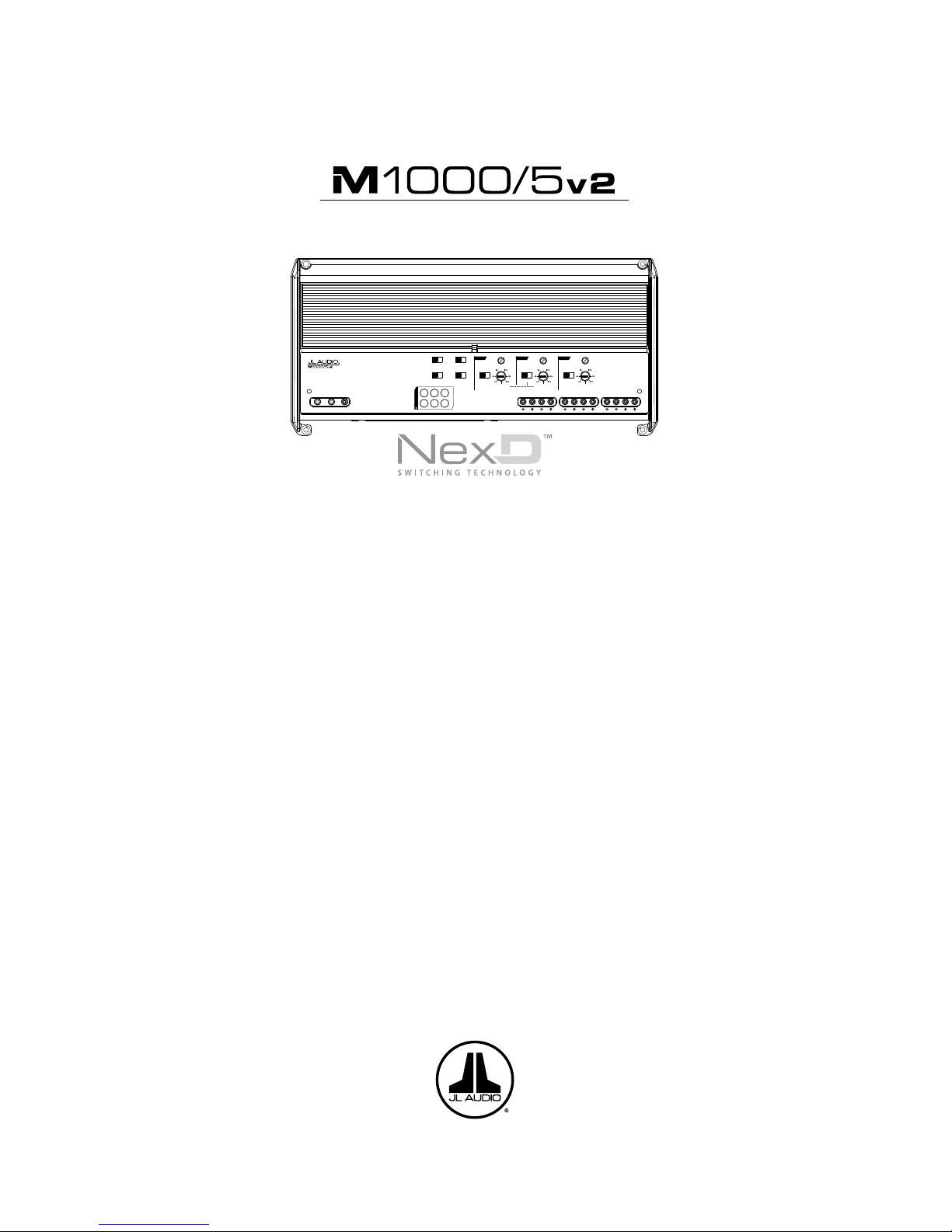
JL Audio M1000/5v2 Owner's Manual
OWNER’S MANUAL
Remote
Level
Mode
Turn-On
Mode
All | Sub Ch.
Input Mode
2 Ch. | 4 Ch. | 6 Ch.
Rem. | Oset | Signal
Input Voltage
Low | High
CH. 3
(L)
CH. 4
(R)
CH. 1
(L)
CH. 1 & 2
CH. 3 & 4 SUB CH.
CH. 2
(R)
HP Filter Mode
Filter Freq. (Hz)
Input
Sens.
O | x1 | x10
Filter Mode
HP Filter Freq. (Hz)
Input
Sens.
O | BP | HP
LP Filter Mode
LP Filter Freq. (Hz)
Input
Sens.
O | 12dB | 24dB
Mono Subwoofer Output
(L)
(R)
CH. 1
CH. 2
CH. 3
CH. 4
SUB
SUB
INPUT SECTION
+12 VDC Ground Remote
Marine 5 Channel Amplifier with 2-Way / 3-Way Crossover
Thank you for purchasing a JL Audio amplifier for
your marine sound system.
Your amplifier has been designed and manufactured to exacting
standards in order to ensure years of musical enjoyment in your vessel.
For maximum performance, we highly recommend that you have
your new amplifier installed by an authorized JL Audio dealer. Your
authorized dealer has the training, expertise and installation equipment
to ensure optimum performance from this product. Should you
decide to install the amplifier yourself, please take the time
to read this manual thoroughly so as to familiarize yourself
with its installation requirements and setup procedures.
If you have any questions regarding the instructions in this
manual or any aspect of your amplifier’s operation, please contact your
authorized JL Audio dealer for assistance. If you need further assistance,
please call the JL Audio Technical Support Department
at (954) 443-1100 during business hours.
1000W 5-Channel Marine Amplier with 2-Way / 3-Way Crossover
2 | JL Audio - M1000/5v2 Owner’s Manual
3
Mounting the amplifier upside down is
strongly discouraged.
Safety Considerations:
Your amplifier needs to be installed in a dr y,
well-ventilated environ ment and in a ma nner
which does not i nterfere wit h your vessel’s safety
equipment (air bags , seat belt systems, AB S brake
systems, etc.). You should also take the time to
securely mou nt the amplifier so t hat it does not
come loose in t he event of a collision or a sudden
jolt to the vessel.
While t his amplifier is specially de signed
for marine applications, it is not waterproof
and it should not be mou nted where it is li kely
to get wet.
Stupid Mistakes to Avoid
• Check before dril ling any holes in your vessel to
make sure t hat you will not be drilli ng throug h
a gas tank, brake line, wiring harness or other
vital vessel system.
• Do not run system wiring out side or underneath
the vessel . This is a n extremely dangerous
practice w hich can result in severe damage to
your vessel a nd person.
• Protect all system wires from sharp metal
edges and wear by caref ully routing them,
tying them down a nd using grommets and
loom where appropriate.
• Do not mount t he amplifier in t he engine
compart ment, under the vessel, on t he roof
or in any other area that w ill expose the
amplif ier circuitry to t he elements.
PROTEC T YOUR HE ARING!
We value you as a long-term cu stomer. For
that reason, we urge you to practice rest raint in
the operat ion of this product so as not to da mage
your hearing and that of others in your vessel.
Studies have shown that cont inuous exp osure to
high sound pressure levels can lead to permanent
(irreparable) hearing loss. This a nd all other
high-power amplifiers are capable of producing
such high sound pressure levels when connected
to a speaker system. Please li mit your continuous
exposure to high volume levels.
While d riving, operate you r audio system in
a manner that stil l allows you to hear necessary
noises to operate your vessel s afely (horns, sirens,
etc .).
SERIAL NUMBER
In the event t hat your amplifier requires
service or is ever stolen, you will need to have
a record of the product’s seria l number. Please
take the time to enter t hat number in the space
provided below. The serial number can be fou nd
on the bottom panel of the amplifier and on the
amplifier packaging.
Serial Number:
INSTALLATION APPLICATIONS
This ampl ifier is designed for operation in
vessels with 12 volt, negat ive-ground electrical
systems. Use of this produc t in vessels with
positive ground and/or voltages other than 12V
may result in d amage to the product and w ill void
th e war rant y.
This produc t is not cert ified or approved for
use in ai rcraf t.
Do not attempt to “bridge” the outputs of this
amplif ier with the outputs of a second amplifier,
including an identica l one.
PLANNING YOUR INSTALLATION
It is important that you ta ke the time to read
this ma nual and t hat you plan out your
installation carefu lly. The following are some
considerations that you must t ake into account
when plann ing your instal lation.
Cooling Efficiency Considerations:
The outer shell of your JL Audio ampl ifier is
designed to remove heat from the a mplifier
circuit ry. For optimum cooling performance, this
outer shell shou ld be exposed to as large a volume
of air as possible. Enclosing the amplifier in a
small, p oorly ventilated chamber can lead to
excessive heat build-up and degraded
performa nce. If an instal lation calls for an
enclosure around the amplifier, we recommend
that this enclosure be ventilated with the aid
of a fan. In normal applications, fa n-cooling
is not necessary.
Remote
Level
Mode
Turn-On
Mode
All | Sub Ch.
Input Mode
2 Ch. | 4 Ch. | 6 Ch.
Rem. | Oset | Signal
Input Voltage
Low | High
CH. 3
(L)
CH. 4
(R)
CH. 1
(L)
CH. 1 & 2
CH. 3 & 4 SUB CH.
CH. 2
(R)
HP Filter Mode
Filter Freq. (Hz)
Input
Sens.
O | x1 | x10
Filter Mode
HP Filter Freq. (Hz)
Input
Sens.
O | BP | HP
LP Filter Mode
LP Filter Freq. (Hz)
Input
Sens.
O | 12dB | 24dB
Mono Subwoofer Output
(L)
(R)
CH. 1
CH. 2
CH. 3
CH. 4
SUB
SUB
INPUT SECTION
+12 VDC Ground Remote
Marine 5 Channel Amplifier with 2-Way / 3-Way Crossover
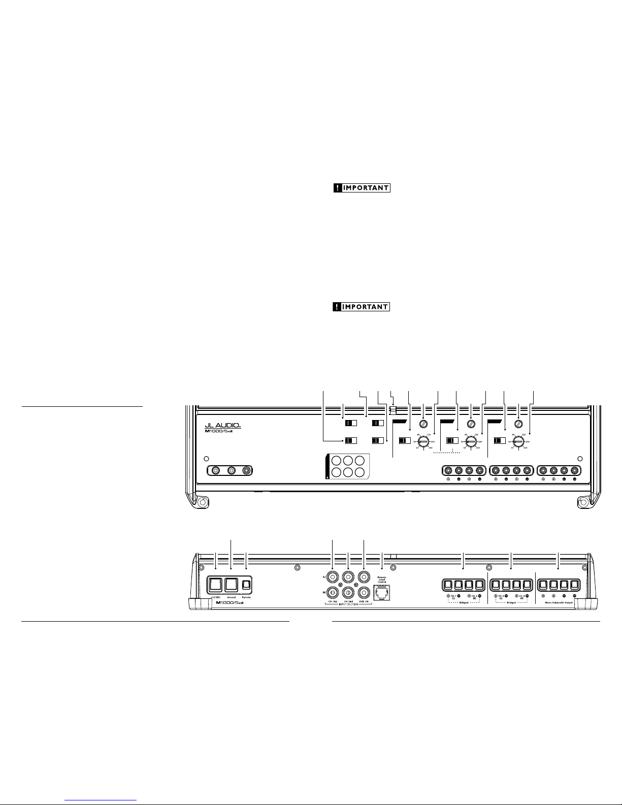
Status
LED
(pg. 11)
Ch. 1 & 2 Filter
Frequency
Selector
(pg. 8)
Ch. 1 & 2
Filter Mode
Selection
(pg. 8)
Ch. 1 & 2 Input
Sensitivity Control
(pg. 7)
Remote
Level Mode
Switch
(pg. 9)
Input
Mode
Switch
(pg. 7)
Input
Voltage
(pg. 7)
Ch. 3 & 4 Filter
Frequency
Selector
(pg. 8)
Ch. 3 & 4
Filter Mode
Selection
(pg. 8)
Ch. 3 & 4 Input
Sensitivity Control
(pg. 7)
Turn-On
Mode
(pg. 6)
Sub. Ch. Filter
Frequency
Selector
(pg. 8)
Sub. Ch.
Filter Mode
Selection
(pg. 8)
Sub. Ch. Input
Sensitivity Control
(pg. 7)
Remote Turn-On
Connector
(pg. 6)
Chassis Ground
Connector
(pg. 5)
Channels 1 & 2
Preamp Input Jacks
(pg. 7)
Subwoofer Ch.
Preamp Input Jacks
(pg. 7)
+12 V Power
Connector
(pg. 5)
Mono
Subwoofer Outputs
(pg. 10)
Channels 3 & 4
Speaker Outputs
(pg. 10)
Channels 1 & 2
Speaker Outputs
(pg. 10)
Jack for
Remote Level
Control Knob
(pg. 10)
Channels 3 & 4
Preamp Input Jacks
(pg. 7)

4 | JL Audio - M1000/5v2 Owner’s Manual
5
POWER CONNECTIONS
Before installi ng the amplifier, disconnect t he
negative (ground) wire f rom the vessel’s batter y.
This will prevent accidental d amage to the system,
the vessel a nd your body during instal lation.
The M1000/5v2’s “+12 V DC” and “Ground”
connections are desig ned to accept 4 AWG
power wi re. 4 AWG is the required wire size for
this amplif ier.
If you are install ing the M1000/5v2 with other
amplif iers and wish to use a single main power
wire, us e 2 AWG or 1/0 AWG main power wire
(depending on the overall c urrent dema nds of all
the ampli fiers in the system). This large power
wire should terminate into a fused distribution
block mounted as close to the a mplifiers as
possible (with in 12 inches / 30cm of wire length).
The fused output of the distribut ion block will
connect to t he M10 00/5v2 with 4 AWG power
wire. JL Audio ECS fu sed dist ribution blocks are
recommended (XD-FDBU-2 and XD-FDBU-4)
Note: Smaller AWG numbers mean bigger
wire and v ice-versa (1/0 AWG is the largest, 2
AWG is smal ler, then 4 AWG, then 8 AWG, etc.).
To connect the power wires to the a mplifier,
first back out the set screw on the top of t he
terminal block, using the suppl ied 2.5 mm hex
wrench. Strip 1/2 inch (12 mm) of insulation from
the end of each w ire and insert the bare wire i nto
the terminal block, seating it firm ly so that no
bare wire is exposed. Whi le holding the wire in
place, tig hten the set screw fir mly, taking care not
to strip the head of the screw.
Any wires run th rough barriers must
be protected w ith a high qualit y rubber
grommet to prevent damage to t he
insulat ion of the wi re. Failu re to do so
may result in a d angerous short circu it.
Many vessels employ small (10 AWG -
6 AWG) wire to grou nd the battery to the vessel
chassis and to connect t he alternator's positive
connection to the batter y. To prevent voltage
drops, these wires should be upgraded to 4
AWG when installing amplifier systems wit h
main fuse ratings above 60A.
It is common for the a lternator to be grounded
through its chassi s. If the alternator is not
grounded t hrough its chassis a nd instead employs
a small (10 AWG - 6 AWG) wire to con nect to
ground, t his wire should al so be upgraded to 4
AWG when inst alling ampli fier systems wit h main
fuse rat ings above 60A.
FUSE REQUIREMENTS
It is absolutely vital that the main power
wire(s) to the amplifier(s) in the system be
fused w ithin 18 inches (45 cm) of the positive
battery post connec tion. The f use value at each
power wire shou ld be high enough for all of the
equipment being run from t hat power wire. If
only the M1000/5v2 is being ru n from that power
wire, we recommend a 80A fuse be used.
If fusing the amplifier nea r its power
connections (when more than one a mp is being
run from t he main power wire), use a 80A fuse.
MAX I™ plastic-body fuses are recom mended.
PRODUCT DESCRIPTION
The JL Audio M100 0/5v2 is a five-channel,
system amplifier utili zing JL Audio NexD™ u ltra-
high speed switching technology for its four main
channels and NexD™ high-speed switching for
its subwoofer channel. The NexD™ technologies
deliver outst anding fidelit y and efficiency.
The M1000/5v2 can be operated w ith a wide
variet y of source units and system conf igurat ions.
TYPICAL INSTALLATION SEQUENCE
The followi ng represents the sequence
for a typical ampli fier installation, using an
after market sou rce unit or OEM I nterface
processor (like the CleanSweep CL441dsp).
Additiona l steps and d ifferent proc edures may
be required in some applications. If you have
any questions, please contact your aut horized
JL Audio dealer for assista nce.
1) Disconne ct the negative battery post
connection and secu re the disconnected cable
to prevent accidental re-connection dur ing
installation. This step is not optional.
2) Run 4 AWG power wire from the battery
location to t he amplif ier mounting location.
Take care to route t he wire in such a way that
it will not be damaged and will not interfere
with vessel operation. Use 2 AWG or larger
power wire and a power distribution block if
additiona l amplifiers are being inst alled w ith
the M1000/5v2.
3) Connec t power wire to the positive battery
post. Fuse t he wire with an appropr iate fuse
block (and connectors) within 18 inches (45
cm) wire length of the positive battery post.
This fus e is essential to protect t he vessel. Do
not instal l the fuse until t he power wire has
been secu rely connected to the ampl ifier.
44) Connect negat ive power wire to the
negative battery post . Use the same size
power wire as t he wire connected to t he
“+12V ” connection (minimum 4 AWG).
5) Run signa l cables and remote turn- on wire
from the sou rce unit to t he amplif ier
mounting location.
6) Run spe aker cable from the speaker systems
to the amplifier mounting locat ion.
7) Securely mount the amplif ier.
8) Connec t the positive and negative power
wires to t he amplifier. A fuse near the
amplif ier is not necessary if the M1000/5v2 is
the only device being run from t he fused main
power wire. If the fused main power wire is
shared by the M1000/5v2 and other amplif iers
or devices, fuse each amplifier/device w ithin
12 inches (30 cm) of wire length, v ia a fused
distribution block or multiple individual f use
blocks/on-boa rd fuses.
9) Connec t the remote turn-on wire
to the amplifier.
10) Connec t the input cables to the amplifier.
11) Con nect the speaker cables to the amplifier.
12) Caref ully review the amplif ier’s control
setti ngs to make su re that they are set
according to the needs of t he system.
13) Inst all t he power wire f use(s) (80A for a
single M1000/5v2) and reconnect t he negative
battery post terminal.
14) Turn on the sou rce unit at a low level
to double-check that the a mplifier is
config ured correctly. Resist t he temptation
to crank it up until you have verified the
control settings.
15) Make necessary adjustments to the input
sensitiv ity controls to obtain t he right
overall out put and the desired balance
in the system. See Appendix A (page 14)
for the recommended input sensit ivity
setting method.
16) Enjoy the fruits of your labor with your
favorite music.
6 | JL Audio - M1000/5v2 Owner’s Manual
7
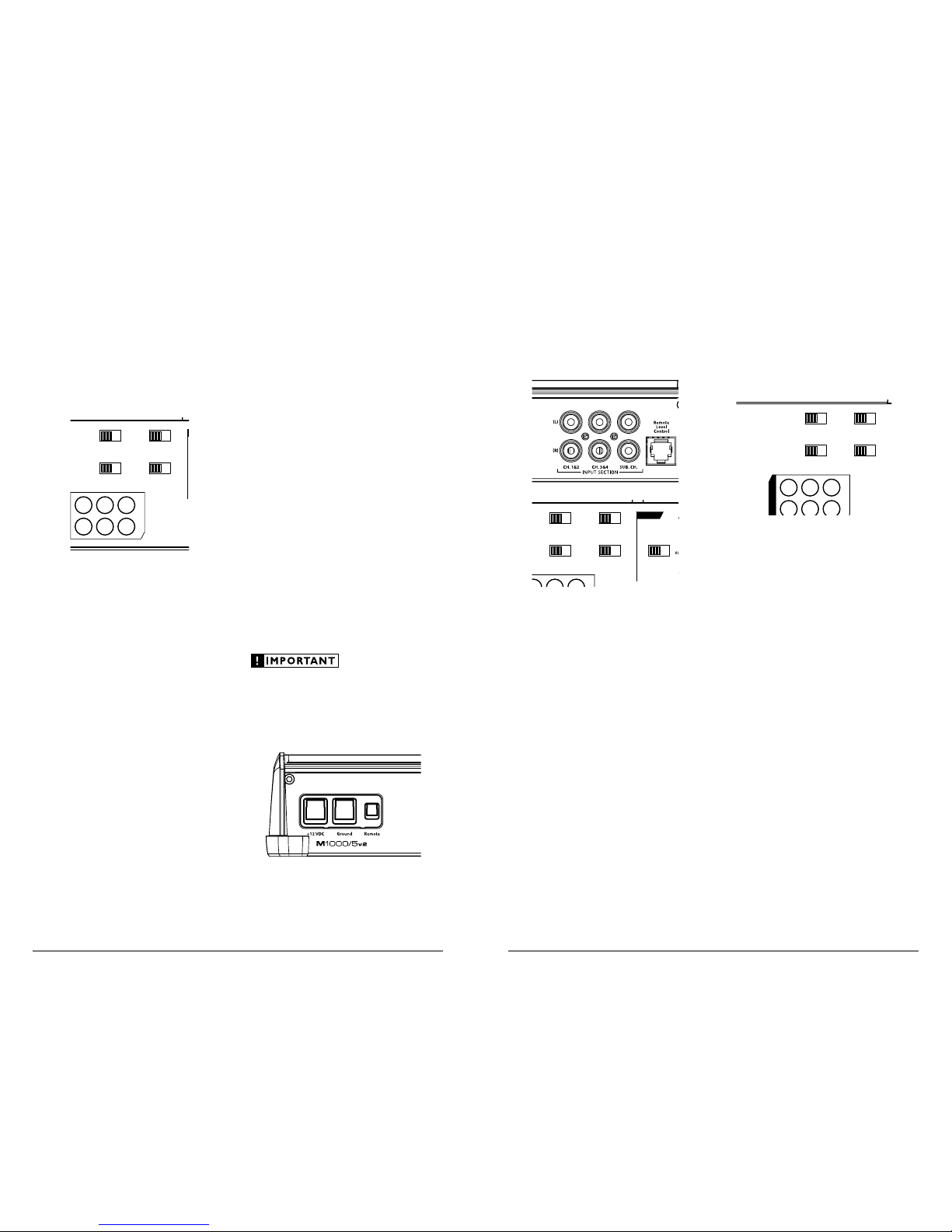
INPUT SECTION
The M1000/5v2’s input sect ion allows
you to send signa ls to the amplifier
section t hrough the use of two, fou r or
six dif ferential-balanced inputs.
Input connect ions are via up to three pa irs of
tradit ional RCA-ty pe jacks.
Remote
Level
Mode
Mode
All | Sub Ch.
Input Mode
2 Ch. | 4 Ch. | 6 Ch.
Rem. | Oset | Signal
Input Voltage
Low | High
CH. 1 & 2
CH. 3 & 4 SUB CH.
HP Filter Mode
Filter Freq. (Hz)
Input
Sens.
O | x1 | x10
Filter Mode
HP Filter Freq. (Hz)
Input
Sens.
O | BP | HP
LP Filter Mode
LP Filter Freq. (Hz)
Input
Sens.
O | 12dB | 24dB
If you wish to s end six discrete cha nnels into the
M1000/5v2, simply u se all six inputs a nd set the
“Input Mode” switch i n the “6 Ch.” position. The
amplif ier will automatic ally combine the lef t and
right “Sub Ch.” input signa ls to mono. If you have
only one chan nel of subwoofer signal avai lable,
it is accepta ble to only use one of the “Sub Ch.”
inputs, but for opt imal gain, we recom mend using a
Y-adaptor and feeding both “Sub C h.” inputs.
If you prefer to use on ly four channels of input
into the M1000/5v2 , set the “Input Mode” switch in
the “4 Ch.” position and use the Ch 1 & 2 and Ch 3
& 4 Inputs. In th is mode, the M1000/5v2 will derive
its subwoofer cha nnel signal from a su m of all four
input signa ls. The bass wil l not fade when the signa l
is faded by the head unit f rom front to rear.
You may also choose to apply on ly two
channel s of input to deliver signal to a ll five
amplif ier channels. To do this, s et the “Input
Mode” switch to “2 Ch.” and use only t he inputs
to channels 1 & 2. In this mode, Channel 3 will
operate wit h the Channel 1 sign al and Channel
4 will operate wit h the Channel 2 signal. The
amplif ier will automatic ally combine the ma in
input signa ls to mono for the Subwoofer Channel.
Input Voltage Range:
Input Voltage Range: A w ide range of sig nal
input voltages c an be accom modated by the
M1000/5v2’s input section (20 0mV – 8V). Th is
wide range is split up into t wo sub-range s,
accessible v ia the “Input Voltage” switch:
“Low”: for preamp level signa ls
“Hi gh”: for speaker level signal s
Remote
Level
Mode
Turn-On
Mode
All | Sub Ch.
Input Mode
2 Ch. | 4 Ch. | 6 Ch.
Rem. | Oset | Signal
Input Voltage
Low | High
CH. 1 & 2 CH. 3 & 4 SUB CH.
HP Filter Mode
Filter Freq. (Hz)
Input
Sens.
O | x1 | x10
Filter Mode
HP Filter Freq. (Hz)
Input
Sens.
O | BP | HP
LP Filter Mode
LP Filter Freq. (Hz)
Input
Sens.
O | 12dB | 24dB
Mono Subwoofer Output
(L)
(R)
CH. 1
CH. 2
CH. 3
CH. 4
SUB
SUB
The “Low ” position on the “Input Voltage”
switch sele cts an i nput sensitiv ity range between
200mV and 2V for all i nput channel s. This me ans
that the “I nput Sens.” rotary control for each
channel section will operate within that voltage
window. If you are using an afterma rket source
unit, with conventiona l preamp-level outputs, t his
is most likely the posit ion that you will use.
The “Hig h” position on the “Input Voltage”
switch sele cts an i nput sensitiv ity range between
800mV and 8V for all input channels. This is
usefu l for certa in high-output preamp level
signals as well as speaker-level output from source
units and small a mplifiers. To use speaker-level
sources, splice the speaker output wires of t he
source unit or small a mplifier onto a pair of RCA
cables or plugs or use the JL Audio ECS Speaker
Wire to RCA adaptor (XD-CLRAIC2-SW).
Line Output C onverters are usual ly not needed
with the M1000/5v2. If you f ind that the output
cannot be re duced suf ficiently with a direct
speaker level signa l applied to the amplif ier and
the “Input Voltage” sw itch in its “High” position,
you may use a “ line output converter” or voltage
divider to re duce the signal level.
TURNON OPTIONS
The M1000/5v2 can be switched on and off
using one of th ree methods, determ ined by the
position of the amplif ier’s “Turn-On Mode”
switch. Ple ase read these option s and decide
which is best suited for your specif ic system.
1) +12V remote turn-on lead
2) Signal-sensing tur n-on circu it.
3) DC offset-sensing tur n-on circuit
Remote
Level
Mode
Turn-On
Mode
All | Sub Ch.
Input Mode
2 Ch. | 4 Ch. | 6 Ch.
Rem. | Oset | Signal
Input Voltage
Low | High
CH. 3
(L)
CH. 4
(R)
CH. 1
(L)
CH. 1 & 2 CH. 3 & 4 SUB CH.
CH. 2
(R)
HP Filter Mode
Filter Freq. (Hz)
Input
Sens.
O | x1 | x10
Filter Mode
HP Filter Freq. (Hz)
Input
Sens.
O | BP | HP
LP Filter Mode
LP Filter Freq. (Hz)
Input
Sens.
O | 12dB | 24dB
Mono Subwoofer Output
(L)
(R)
CH. 1
CH. 2
CH. 3
CH. 4
SUB
SUB
+12 V Remote Turn-On : This is the preferred
method for tu rning the amplifier on/off. T he
amplif ier will turn on when +12 V is present at
its “Remote” input and turn off when +12 V is
switched of f. This +12V remote turn-on signa l is
typically cont rolled by a source unit’s remote
turn-on wire. The M1000/5v2’s “Remote” turn-
on connector w ill accept 18 AWG – 12 AWG
wire. To connect t he remote turn-on wire to
the ampli fier, first back out the set screw on the
top of the term inal block, using t he supplied 2.5
mm hex wrench. Strip 1/2 inch (12mm) of wire
and inser t the bare wire into t he terminal block,
seating it f irmly so that no ba re wire is exposed.
While holding the w ire in the terminal, tig hten
the set screw firmly, taki ng care not to strip the
head of the screw and mak ing sure that the wire
is firmly gripped by the set screw.
If a source un it does not have a dedicated
remote turn-on output, consider one of t he
following a lternative turn-on options:
These met hods are us eful when a conventional
+12 V remote turn-on signal is not available in a
system. These allow you to operate the amplif ier
without hav ing to locate a remote turn-on lead at
the source u nit, which can be ver y useful when
interfacing the amplifier with OEM (factory)
audio systems that do not use conventional +12 V
turn-on le ads.
Depending on the cha racteristics of the audio
signal, one of the following methods may work
better t han the other. We recommend trying DC
Offset-Sensing first as it does not require a long
delay to turn the system off af ter the signal is
shut off.
DC Offset-Sensing: The a mplifier will turn on
and off by detecting the presence of a very smal l
DC signa l (of fset) that is typical in the audio
output of most OEM (factory) source units and
amplif iers. The amplifier will turn on a nd off in
reaction to the presence or absence of t his DC
Offset . The sensit ivity of t his circuit is desig ned
for high-level (spea ker level) signals, not for lowlevel (preamp level) signals . The circu it senses the
“Ch. 1” (left) input signal on ly.
Signal-Sensi ng: The amplifier w ill turn on
and off by detecting the presence of a f ull-range
audio signal at its “Ch 1” (left) input. After several
minutes of no sig nal, the amplif ier will shut off.
The sensitivity of t his circ uit is desig ned for
high-level (spea ker level) signals, not for low-level
(preamp level) signals. The circuit is tuned to
react to signals at mid-range frequencies. This
prevents false switch ing from sig nals created by
moving loudspeakers that are in paral lel with the
amplif ier’s input signal.
In signal and DC sensing applications, the
am plif ier’s “Remote” turn-on terminal becomes
a remote turn-on output. Th is allows the
M1000/5v2 to turn on other amplifiers i n the
audio system that do not have signal sensi ng.
 Loading...