

JL Audio JX360, JL364, JX3640/4, JX360/4 Owner's Manual

Thank you for purchasing a JL Audio amplifier for
your automotive sound system.
Your amplifier has been designed and manufactured to exacting
standards in order to ensure years of musical enjoyment in your vehicle.
For maximum performance, we highly recommend that you have
your new amplifier installed by an authorized JL Audio dealer. Your
authorized dealer has the training, expertise and installation equipment
to ensure optimum performance from this product. Should you
decide to install the amplifier yourself, please take the time
to read this manual thoroughly so as to familiarize yourself
with its installation requirements and setup procedures.
If you have any questions regarding the instructions in this
manual or any aspect of your amplifier’s operation, please contact your
authorized JL Audio dealer for assistance. If you need further assistance,
please call our Technical Support Department
at (954) 443-1100 during business hours.
OWNER’S MANUAL
360W 4-Channel, Full-Range Amplifier
2 JL Audio JX360 /4 3
ENGLISH
INSTALLATION APPLICATIONS
This ampl ifier is designed for operation in
vehicles with 12 volt, negat ive-ground electrical
systems. Use of this product in vehicles with
positive ground and/or voltages other than 12V
may result in d amage to the product and w ill void
th e war rant y.
This product is not certified or approved for
use in aircraft.
Do not attempt to “ bridge” the outputs of this
amplif ier with the outputs of a second amplifier,
including an identica l one.
PLANNING YOUR INSTALLATION
It is important that you ta ke the time to read
this manual and that you plan out your
installation carefu lly. The following are some
considerations that you must take into account
when planning your instal lation.
Cooling Efficiency Considerations:
The outer shell of your JL Audio a mplifier is
designed to remove heat from the amplif ier
circuitry. For optimum cooling performance, this
outer shell shou ld be exposed to as large a volume
of air as possible. Enclosing the amplifier in a
small, poorly ventilated chamber can lead to
excessive heat build-up and degraded
performa nce. If an instal lation calls for an
enclosure around the amplifier, we recommend
that this enclosure be ventilated with the aid
of a fan. In normal applications, fa n-cooling
is not necessary.
IMPORTANT
!
Mounting the amplifier upside down is
strongly discouraged.
If mounting the amplifier under a seat,
make sure t here is at least 1 inch (2.5 cm) of
space above the amplif ier’s outer shell to permit
proper cooling.
Safety Considerations:
Your amplifier needs to be installed in a dr y,
well-ventilated environ ment and in a manner
which does not i nterfere wit h your vehicle’s safety
equipment (air bags, seat belt systems, ABS brake
systems, etc.). You should also take the time to
securely mount the amplifier so that it does not
come loose in t he event of a collision or a sudden
jolt to the vehicle.
Stupid Mist akes to Avoid
• Check before dril ling any holes in your vehicle
to make sure that you wi ll not be drilli ng
through a gas tan k, brake line, wiring harness or
other vital vehicle system.
• Do not run system wiring out side or underneath
the vehicle. This is an extremely dangerous
practice which can result in severe damage to
your vehicle and person.
• Protect all system wires from sharp metal
edges and wear by caref ully routing them,
tying them down and using grommets and
loom where appropriate.
• Do not mount t he amplifier in the engi ne
compart ment, under the vehicle, on the roof
or in any other area that w ill expose the
amplif ier circuitry to the elements.
PROTEC T YOUR HE ARING!
We value you as a long-term customer. For
that reason, we urge you to practice restraint in
the operation of this product so as not to damage
your hearing and that of others in your vehicle.
Studies have shown that cont inuous exposure to
high sound pressure levels can lead to permanent
(irreparable) hearing loss. This a nd all other
high-power amplifiers are capable of producing
such high sound pressure levels when connected
to a speaker system. Please li mit your continuous
exposure to high volume levels.
While d riving, operate your audio system in
a manner that stil l allows you to hear necessary
noises to operate your vehicle safely (horns,
sirens, etc.).
SERIAL NUMBER
In the event that your amplifier requires
service or is ever stolen, you will need to have
a record of the product’s seria l number. Please
take the time to enter t hat number in the space
provided below. The serial number can be fou nd
on the bottom panel of the amplifier and on the
amplifier packaging.
Serial Number:
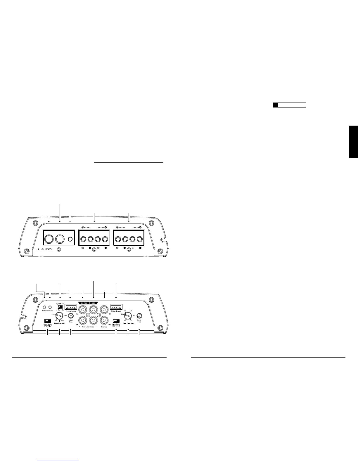
CH 1 & CH 2
Preamp
Input Jacks
(pg. 6)
CH 3 & CH 4
Preamp Input Jacks
(pg. 6)
Protection Status
Indicator
(pg. 11)
Power Status
Indicator
(pg. 11)
High-Level
Input Jack
(pg. 6,7)
Input Mode
Selector
(pg. 7)
High-Level
Input Jack
(pg. 6,7)
Input
Sensitivity
Control
(pg. 8)
Filter Mode
Selector
(pg. 8)
Left & Right
Preamp Output Jacks
(pg. 9)
Filter
Frequency
Control
(pg. 8)
Input
Sensitivity
Control
(pg. 8)
Filter Mode
Selector
(pg. 8)
Filter
Frequency
Control
(pg. 8)
+12 VDC Ground Remote
CH. 3
(L)
CH. 4
(R)
CH. 1
(L)
CH. 2
(R)
BridgedBridged
Remote Turn-On
Connector
(pg. 6)
+12 V Power
Connector
(pg. 5)
Chassis Ground
Connector
(pg. 5)
CH 1 & CH 2
Speaker Outputs
(pg. 10)
CH 3 & CH 4
Speaker Outputs
(pg. 10)

4 JL Audio JX360 /4 5
ENGLISH
POWER CONNECTIONS
Before installi ng the amplifier, disconnect t he
negative (ground) wire f rom the vehicle’s battery.
This will prevent ac cidental damage to t he system,
the vehicle a nd your body during instal lation.
+12 VDC Ground
Remote
CH. 3
(L)
CH. 4
(R)
CH. 1
(L)
CH. 2
(R)
BridgedBridged
The JX360/4’s “+12VD C” and “Ground ”
connections are desig ned to accept 4 AWG power
wire. 4 AWG is a minimum power wire siz e for
this amplif ier.
If you are install ing the JX360/4 with other
amplif iers and wish to use a single main power
wire, use 2 AWG or larger main power wire
(depending on the overall c urrent demands of all
the ampli fiers in the system). This 2 AWG or
larger power wire should ter minate into a fused
distribution block mounted as close to the
amplif iers as possible and should connect to the
JX360/4 with 4 AWG power wire.
Note: Smaller AWG numbers mean bigger wire
and vice-versa (1/0 AWG is the largest, 2 AWG is
smaller, then 4 AWG, then 8 AWG, etc.).
To connect the power and ground wi res
to the amplifier, strip 1/2-inch (12 mm) of
insulat ion from each wire and insert the bare
wire into t he the appropriate terminal block
positions on the JX360/4. Use the supplied
2.5 mm hex w rench to secure the wire via
the screw on t he top of each terminal.
The “GROUN D” connection should be made
using 4 AWG wire and should be kept as short
as possible, while accessing a solid piece of sheet
metal in the vehicle. The surface of the sheet
metal shou ld be sanded at the contact point
to create a clean, metal-to-metal connection
between t he chassis and the termination of t he
ground wi re. The use of a #10 sheet metal screw
and star washer to lock dow n the connection is
advisable. Alternatively, you can use a specialized
grounding lug, such as the JL Audio XB-MGLU.
Any wires run th rough metal barr iers (such as
firewa lls), must be protected with a high qua lity
insulat ing grommet to prevent damage to the
insulat ion of the wire. Failure to do so may result
in a dangerous short circuit.
IMPORTANT
!
Many vehicles employ small (10 AWG -
6 AWG) wire to grou nd the battery to the
vehicle chassis and to connect the alternator’s
positive connection to the bat tery. To prevent
voltage drops, t hese wires should be upgraded
to 4 AWG when installing amplifier systems
with mai n fuse ratings above 60A.
FUSE REQUIREMENTS
An appropriate f use at the main power wire(s)
to the amplifier(s) is vita l for vehicle safety! This
fuse must be insta lled within 18 inches (45 cm)
of the positive battery post connection. If t he
JX360/4 is t he only device connected to this main
wire, use a 50A AGU or MAXI® fuse (no other
fuse is required in t his situation).
When running multiple devices from one
main power wire, the main fuse value and rating
of the main power wire must be high enough
for all of the equipment being run from it. Use a
fused distribution block to split the main power
wire feed to each device, with appropriate fusing
and power wire for each device.
PRODUCT DESCRIPTION
The JL Audio JX360/4 is a four-channel,
full-range audio a mplifier utili zing Class A/B
technolog y for all channels.
The JX360/4 can be operated with a wide
variet y of source units and system configurations.
For detailed specifications, please refer to
Appendix B (page 13).
TYPICAL INSTALLATION SEQUENCE
The followi ng represents the sequence
for a typical ampli fier installation, using an
aftermarket sou rce unit or OEM Interface
product. Additional steps and different
procedures may be required in some applications.
If you have any questions, please contact you r
authorized JL Audio dealer for assistance.
1) Disconnec t the negative battery post
connection and secu re the disconnected cable
to prevent accidental re-connection during
insta llation. This step is not opt ional.
2) Run 4 AWG power wire from the battery
location to the amplif ier mounting location,
taki ng care to route it in such a way that it
will not be damaged and will not interfere
with vehicle operation. Use 2 AWG or larger
power wire and a power distribution block if
additiona l amplifiers are being installed with
the JX360/4.
3) Connec t power wire to the positive battery
post. Fuse the wire w ith an appropriate fuse
block (and connectors) within 18 inches (45
cm) wire length of the positive battery post.
This fus e is essential to protect t he vehicle.
Do not insta ll the fuse until t he power wire
has been sec urely connected to the a mplifier.
4) Run signal c ables and remote turn-on w ire
from the source unit to t he final amplifier
mounting location.
5) Ru n speaker cables from the speaker systems
to the amplifier mounting location.
6) Find a good, solid metal grounding point
close to the a mplifier and connec t the
negative power wire to it using appropriate
hardware. Use the same size power wire as the
wire connected to the “+12V DC” connection
(minimum 4 AWG), no longer than 36 inches
(90 cm) from the amplifier to t he ground
connection point. In some vehicles, it may be
necessary to upgrade the battery ground wire.
(See page 5 for important notice).
7)
Securely mount the ampl ifier using
appropriate hardware.
8) Connect the positive and negative power
wires to t he amplifier.
9) Connect the remote turn-on wire
to the amplifier.
10) Connec t the input cables to the amplifier.
11) Con nect the speaker cables to the amplifier.
12) Caref ully review the amplif ier’s control
settings to make sure that they are set
according to the needs of t he system.
13) Install t he power wire fuse (50A for a
single JX360/4) and reconnect the negative
battery post terminal.
14) Turn on the sou rce unit at a low level
to double-check that the a mplifier is
config ured correctly. Resist t he temptation
to crank it up until you have verified the
control settings.
15) Make necessary adjustments to the input
sensitivity controls to obtain t he right
overall out put and the desired balance
in the system. See Appendix A (page 12)
for the recommended input sensit ivity
setting method.
16) Enjoy the fruits of your labor with your
favorite music.
6 JL Audio JX360 /4 7
ENGLISH
IMPORTANT
!
Make sure you observe correct polarity in
making the “Hi-Level Input” connections.
Failure to do so will reduce bass and affect
stereo imaging.
The connec tions for the “Hi-Leve l Inputs” plug wires
are as follow s from left to right on t he plug:
Channels 1&2 (FRONT)
White: L eft Positive (+)
White/Black: Left Negative (–)
Black: Common Ground (rarely used)*
Gray: Right Positive (+)
Gray/Black: Right Negat ive (–)
Channels 3&4 (REAR or SUB)
Green: Lef t Positive (+)
Green/Black: Lef t Negative (–)
Black: Common Ground (rarely used)*
Purple: Right Posit ive (+)
Purple/ Black: Right Negat ive (–)
*The only time you will use the Common Ground
connections is with some older (pre-1980’s) factory
systems or head units that ground their speakers to
chassis ground. To use these connections, ground
the black wires on the plugs to chassis ground and
only connect the Left and Right Positive plug wires
to the factory radio outputs.
“Input Mode” Switc h
If you wish to send four discrete channels of
input into the J X360/4, simply use all four inputs
(Channels 1 & 2 and Channels 3 & 4) and set the
“Input Mode” switch to “4 Ch.”.
If you wish to feed all four channels by using
only two cha nnels of input, set the “Input Mode”
switch to “2 Ch.” and use only the inputs to
Channels 1 & 2.
When Bridg ing the Amplifier:
If you are bridg ing the amplifier down
to two chan nels in a stereo application,
you must set the "Input Mode" switch to
the "4 Ch." position and feed the input of
each bridged channel pa ir individual ly.
For mono applications (where both bridged
channel pairs wi ll reproduce the same signal), you
can selec t the "2 Ch." position and only feed the
Ch. 1 & 2 Inputs.
IMPORTANT
!
Any bridged channel pair must be fed by both
Input Channel s corresponding to it (Lef t and
Right). Failu re to do so will result in signif icant
audible distortion.
See "Bridging Considerations" section on Page
10 for further information.
TURN ON LEAD
The JX360/4 is turned on and off
using a convent ional +12V remote tur n-
on lead, ty pically controlled by the
source unit’s remote turn-on output.
+12 VDC Ground Remote
CH. 3
(L)
CH. 4
(R)
CH. 1
(L)
CH. 2
(R)
BridgedBridged
The amplifier w ill turn on when +12V is
present at its “Remote” input a nd turn off when
+12V is switched off. If a source unit does not
have a dedicated remote turn-on output, the
amplif ier’s turn-on lead can be connected to +12V
via a switch that derives power from an ignitionswitched ci rcuit.
18 AWG w ire is more than adequate for the
remote turn-on connect ion. To con nect the
remote turn-on wire to t he amplifier, strip 1/2inch (12 mm) of insulation from the w ire and
insert it i nto the “Remote” receptacle on t he
power connector. Tighten the connector down
using the supplied 2.5 mm hex wrench.
INPUT SECTIONS
The JX360/4’s has two input sections: one for
Channels 1&2 and another for Channels 3&4.
These input sections a llows you to send signals to
the ampli fier sections through the use of either
two or four inputs. Each input section offers
two input connection met hods, one for highlevel (speaker level) signals and one for low-level
(preamp level) signals.
1) Low-L evel Inputs: A standard left /
right pai r of RCA type jacks in the
“Low-Level Inputs” section is used for
preamp level (low-level) signal input
on the JX360/4. This is the preferred
connection method whenever available.
2) Hi-Level Inputs: If your system does not offer
a preamp level sig nal option, you can connect
speaker level signa ls directly to the “H i-Level
Inputs” connectors using t he supplied mating
connectors and wire harnesses. Simply splice
the appropriate left/right and positive/negative
wires to the included ha rnesses and plug the
harness into the “Hi-L evel Inputs” connectors
on the ampli fier. The JX360/4 will attenuate
the high-level signa ls to make them compatible
with its i nput stages.
8 JL Audio JX360 /4 9
ENGLISH
“LP ” (Low- Pas s): Configu res the filter to
attenuate frequencies above the selected filter
frequency at a rate of 12dB per octave. This is
useful for connect ion of subwoofer(s) to one
or both of the J X360/4’s channel pairs in a
bi-amplif ied system.
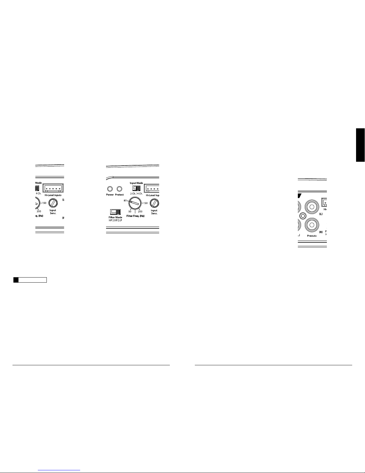
2) “Filter Freq. (Hz)” A simple rotary control
in each cha nnel section adjusts t he filter
cutoff frequency of the filter t ype you have
selected w ith the “Filter Mode” switch. This
control will have no effect if you have selected
the “Off ” position for the “Filter Mode ”).
Each fi lter in the JX360/4 is fully va riable
between 50 Hz and 200 Hz. The "8 0"
Hz position is a good star ting point for
tuning systems ut ilizing typical subwoofers
and component or coa xial speakers.
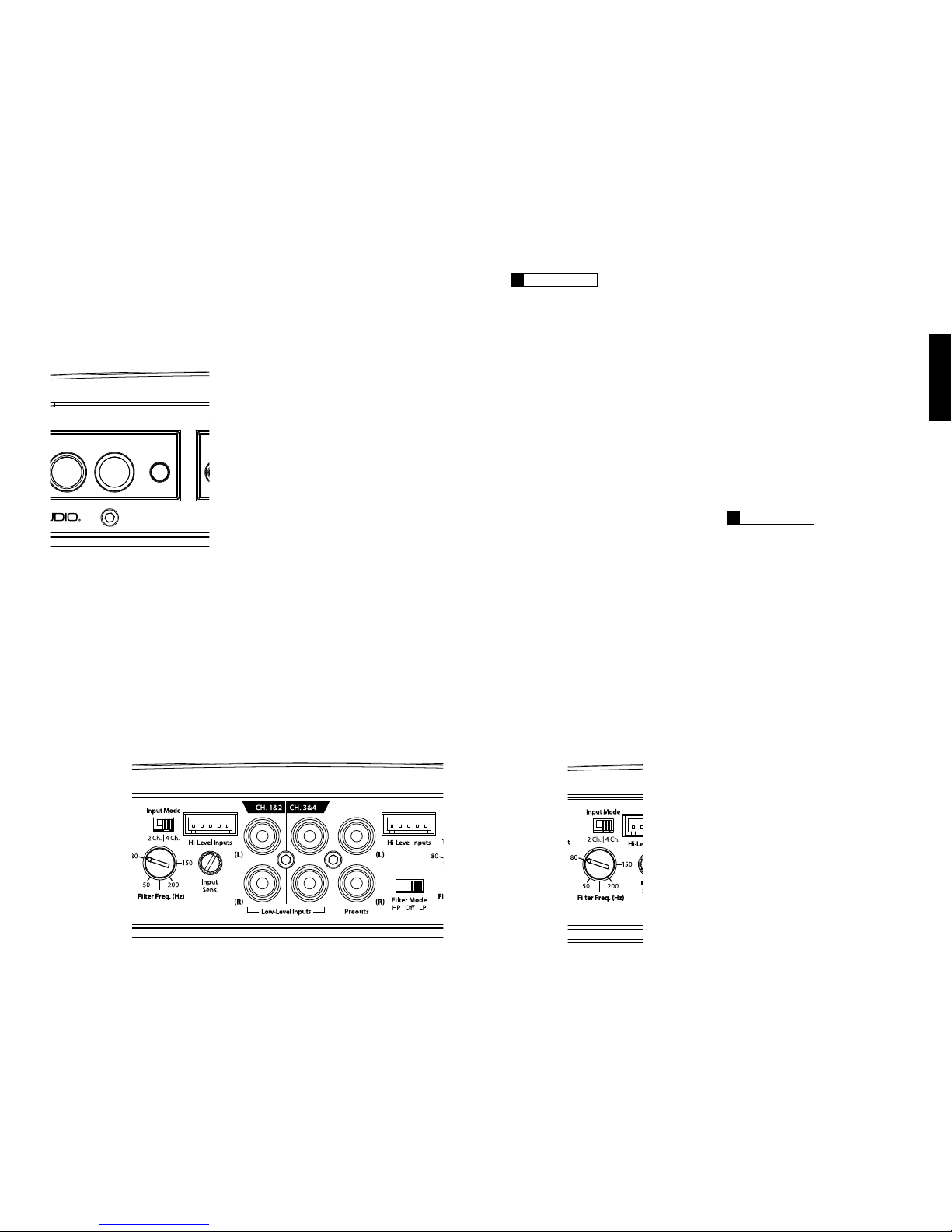
INPUT SENSITIVITY CONTROLS
The controls labeled “Input Sens.” located in
each channel pair's control section can be used
to match the sou rce unit’s output voltage to the
input stage of each pair of amplifier channels
for maximum clean output. Rotating the control
clockwise will result i n higher sensitivit y (louder
for a given input volta ge). Rotating the control
counter-clockwise will result in lower sensitivity
(quieter for a given input voltage.)
To properly set the ampli fier for maximum
clean output , please refer to Appendix A (page
12) in this manual. After using this procedure,
you can then adjust any or all “Input Sens .”
levels downward if this is required to achieve t he
desired system bala nce.
IMPORTANT
!
Do not increase any “Input Sens.” se tting for
any channel(s) of any amplifier i n the system
beyond the ma ximum level established during
the procedure outlined i n Appendix A (page
12). Doing so wil l result in audible distor tion
and possible speaker da mage.
FILTER CONTROLS
The active filter bu ilt into each channel
section of t he JX360/4 can be used to elimi nate
potentially harmful and/or undesi red frequencies
from mak ing their way through the amplifier
sections to the spea ker(s). This serves to improve
tonal balance and to avoid distort ion and possible
speaker failure. Correct u se of these filters c an
substant ially increase t he longevity and fidelity
of your audio system.
1) “Filter Mode” Control: The JX360/4 employs a
12dB per octave filter for each pair of channels
(one filter for channels 1&2 and another filter
for channels 3&4). Each of these f ilters can
be configured independently into one of two
filter t ypes or defeated completely by way of the
three-position “Filter Mo de” switches:
“HP” (High-Pass): Configures the filter to
attenuate frequencies below the selected filter
frequency at a rate of 12dB per octave. This is
useful for connect ion of component speakers
to one or both of the JX360/4’s channel pairs in
a bi-amplif ied system.
Of f”: Defeats the filter completely, allowing
the full range of f requencies present at the
inputs to feed the amplifier. This is usefu l
for systems utilizing outboard crossovers or
requiri ng full-range reproduction from one or
both of the J X360/4’s channel pairs.
PREOUTS
The JX360/4 incorporates a pass-t hrough
preamp output (Preouts) section, so that
additiona l amplifiers can be easily added to
the system. This pass-through pre-amp output
delivers a summed stereo signal, combining t he
Ch 1 and 3 sig nals into a Left Preamp Output
Signal a nd the Ch. 2 and 4 signals into a Rig ht
Channel Preamp Out put signal. Only signals
applied to the L ow-Level inputs are passed
through the Preout s. Input signals applied to
the High-L evel inputs will not pass through the
Preouts.
The preamp output signal is not affec ted by
any crossover f ilter selected (if the input signal is
full-range, the preamp output will be f ull-range).
Note: The signal level of the “Preouts” is always
line-level (low voltage).

10 JL Audi o JX360 /4 11
ENGLISH
AMPLIF IER STATUS INDICATOR LI GHTS &
PROTECTION CIRCUITRY
There are two status indicator lights on the
control panel of t he amplifier.
1) “Power ” (Green): lights to indicate that the
amplif ier is turned on and operating normally.
Located at t he far left of the control panel.
2) “Protec t” (Red): Indicates that the amplif ier
protection circuitry has been activated
to prevent product failure due to t hermal
overload, short-circuit or a dangerously
low impedance connected to the ampl ifier
outputs. Con necting the spea ker outputs
to an impedance lower than 2 ohms stereo
(4 ohms bridged) wi ll cause this protec tion
mode to activate. When t his protection mode
is activated, the a mplifier will shut down to
protect its ci rcuitr y. W hen the problem is
corrected, the ampl ifier will return to normal
operation and the “Protec t” LED will shut off.
SERVICING YOUR AMPLIFIER
If your amplifier fa ils or malfunc tions, please
return it to your authorized JL Audio dealer so
that it may be sent in to JL Audio for ser vice.
There are no user serviceable parts or fuses inside
the ampli fier. The unique nature of t he circuitry
in the JL Audio amplifiers requires specifica lly
trained serv ice personnel. Do not attempt
to service the ampl ifier yourself or through
unauthorized repa ir facilities. T his will not only
void the warranty, but may resu lt in the creation
of more problems within the amplif ier.
If you have any ques tions about the insta llation
or setup of the a mplifier not covered i n this manual,
please contac t your dealer or techn ical support.
JL Audio Technical Su pport:
(954) 443-1100
9:00 AM – 5:30 PM (Eastern T ime Zone)
Monday - Friday
SPEAKER OUTPUTS
The JX360/4’s speaker outputs are designed to
accept 16 AWG - 8 AWG wire.
Each pair of the JX360/4’s channels are
designed to deliver power into speaker loads equal
to or greater than 2 ohms per channel when using
a “stereo” configurat ion and speaker loads equal
to or greater than 4 ohms per bridged pair of
channels when using a “ bridged” configurat ion.
CH. 3
(L)
CH. 4
(R)
CH. 1
(L)
CH. 2
(R)
Bridged
Bridged
IMPORTANT
!
Speaker loads below 2 ohms nominal per
channel a re not recommended and wil l cause
the amplifier to enter a protection mode.
BRIDGING CONSIDERATIONS
Bridging is the practice of combining the
output of two amplifier channels to drive a single
load. When bridged, each channel produces
signals of equal magnitude, but opposite polarity.
The combined out put of the two channels
provides twice the out put voltage available from
a single cha nnel. The JX360/4 has been designed
for bridging of its channel pairs w ithout the need
for input inversion adaptors.
To bridge a pair of chan nels, use the
“Left +” and “Right –” speaker connectors only
(the “Left –” a nd “Right +” remain unu sed).
When bridged, each cha nnel will deliver
optimum power into a 4 ohm load.
IMPORTANT
!
When a pair of JX360/4 channels a re bridged,
they will deliver 180W x 1 into a 4 ohm load or
140W x 1 into an 8 ohm load. Operating a
pair of bridged channels into a load lower
than 4 ohms i s not recommended and wil l
cause the amplifier to enter a protection mode.
IMPORTANT
!
Any bridged channel pair must be fed by both
Input Channel s corresponding to it (Lef t and
Right). Failu re to do so will result in signif icant
audible distortion.
When a pair of the JX360/4’s channels are
operating in bridged mode, the output will be in
mono (only one channel). This mono chan nel
can contain right channel only information,
left channel only information or t he sum of
the information from both the right and lef t
channels. In order to achieve one of these options,
config ure the inputs to that pair of channels in
one of these two ways:
1) Left Chan nel Only or Right Channel Only
Information: If you wish to send a left-only
or right-only signal to a pa ir of the JX360/4’s
channels, use a “Y-Adaptor” to split the single
channel signal into both left and right RCA
inputs. This option is useful when using a
pair of the JX360/4’s channels to drive left
channel speakers on ly and the other pair of
the JX360/4’s channels to dr ive right channel
speakers only.
2) Left + Right Channel Information:
When bridged and fed by a stereo input, a pair
of the JX360/4’s channels will automatically
combine the left and right channels into a
summed mono (left + r ight) channel. This
option is useful when using a pair of the
JX360/4’s channels to drive a subwoofer system
or a summed mono center channel.
 Loading...