

JL Audio iM700/5, M700/5 Owner's Manual

Thank you for purchasing a JL Audio amplifier for
your marine sound system.
Your amplifier has been designed and manufactured to exacting
standards in order to ensure years of musical enjoyment in your vessel.
For maximum performance, we highly recommend that you have
your new amplifier installed by an authorized JL Audio dealer. Your
authorized dealer has the training, expertise and installation equipment
to ensure optimum performance from this product. Should you
decide to install the amplifier yourself, please take the time
to read this manual thoroughly so as to familiarize yourself
with its installation requirements and setup procedures.
If you have any questions regarding the instructions in this
manual or any aspect of your amplifier’s operation, please contact your
authorized JL Audio dealer for assistance. If you need further assistance,
please call the JL Audio Technical Support Department
at (954) 443-1100 during business hours.
OWNER’S MANUAL
700W Marine 5-Channel Amplier with 2-Way / 3-Way Crossover
2 | JL Audio - M700/5 Owner’s Manual
3
PLANNING YOUR INSTALLATION
It is important that you ta ke the time to read
this ma nual and that you plan out your
installation carefu lly. The following are some
considerations that you must t ake into ac count
when plann ing your instal lation.
Cooling Efficiency Considerations:
The outer shell of your JL Audio ampl ifier is
designed to remove heat from the amplif ier
circuit ry. For optimum cooling performance, thi s
outer shell shou ld be exposed to as large a volume
of air as possible. Enclosing the amplifier in a
small, poorly ventilated chamber can lead to
excessive heat build-up and degraded
performa nce. If an instal lation calls for an
enclosure around the amplifier, we recommend
that this enclosure be ventilated with the aid
of a fan. In normal applic ations, fa n-cooling
is not necessary.
Mounting the amplifier upside down is
strongly discouraged.
Safety Considerations:
Your amplifier needs to be in stalled in a dr y,
well-ventilated environ ment and in a manner
which does not i nterfere with your vess el’s factory
insta lled electronic dev ices. You should also take
the time to securely mount the ampl ifier using the
supplied screws so that it does not come loose i n
the event of a col lision or a sudden jolt to the vessel.
Stupid Mist akes to Avoid
• Check before d rilling any holes in your vessel to
make sure t hat you will not be drilli ng through
the hull, a fuel tank, fuel line, wiring ha rness or
other vital vessel system.
• Do not run sy stem wiring outside or underneath
the vessel . This is a n extremely dangerous
practice w hich can result in severe dama ge to
your vessel a nd person.
• Protect all system wires f rom sharp edges
(metal, fiberglass, etc.) by careful ly routing
them, ty ing them down and usi ng grommet s
and loom where appropriate.
• Do not mount the amplif ier in the engine
compart ment or in any other area that will
expose t he amplifier circuitry to the elements.
While t his amplifier is specially designed
for marine applications, it is not waterproof
and it should not be mou nted where it is
likely to get wet.
PROTEC T YOUR HE ARING!
We value you as a long-term customer. For
that reason, we urge you to practice rest raint in
the operation of this product so as not to damage
your hearing and that of others in your vessel.
Studies have shown that cont inuous exposure to
high sound pressure levels can lead to permanent
(irreparable) hearing los s. This a nd all other
high-power amplifiers are capable of producing
such high sound pressure levels when connected
to a speaker system. Please li mit your continuous
exposure to high volume levels.
While d rivi ng, operate your audio system in
a manner that stil l allows you to hear nece ssar y
noises to operate your vessel s afely (horns,
sirens, etc.).
SERIAL NUMBER
In the event t hat your ampl ifier requires
service or is ever stolen, you will need to have
a record of the product’s seria l number. Please
take the time to enter t hat number in the space
provided below. The serial number can be fou nd
on the bottom panel of the a mplifier and on the
amplifier packaging.
Serial Number:
INSTALLATION APPLICATIONS
This ampl ifier is designed for operation in
vessels with 12 volt, negat ive-ground electrical
systems. Use of this product in vessels with
positive ground and/or voltages other than 12V
may result in d amage to the product and w ill void
th e war rant y.
This produc t is not cert ified or approved for
use in ai rcraf t.
Do not attempt to “bridge” the output s of this
amplif ier with the outputs of a second amplifier,
including an identica l one.
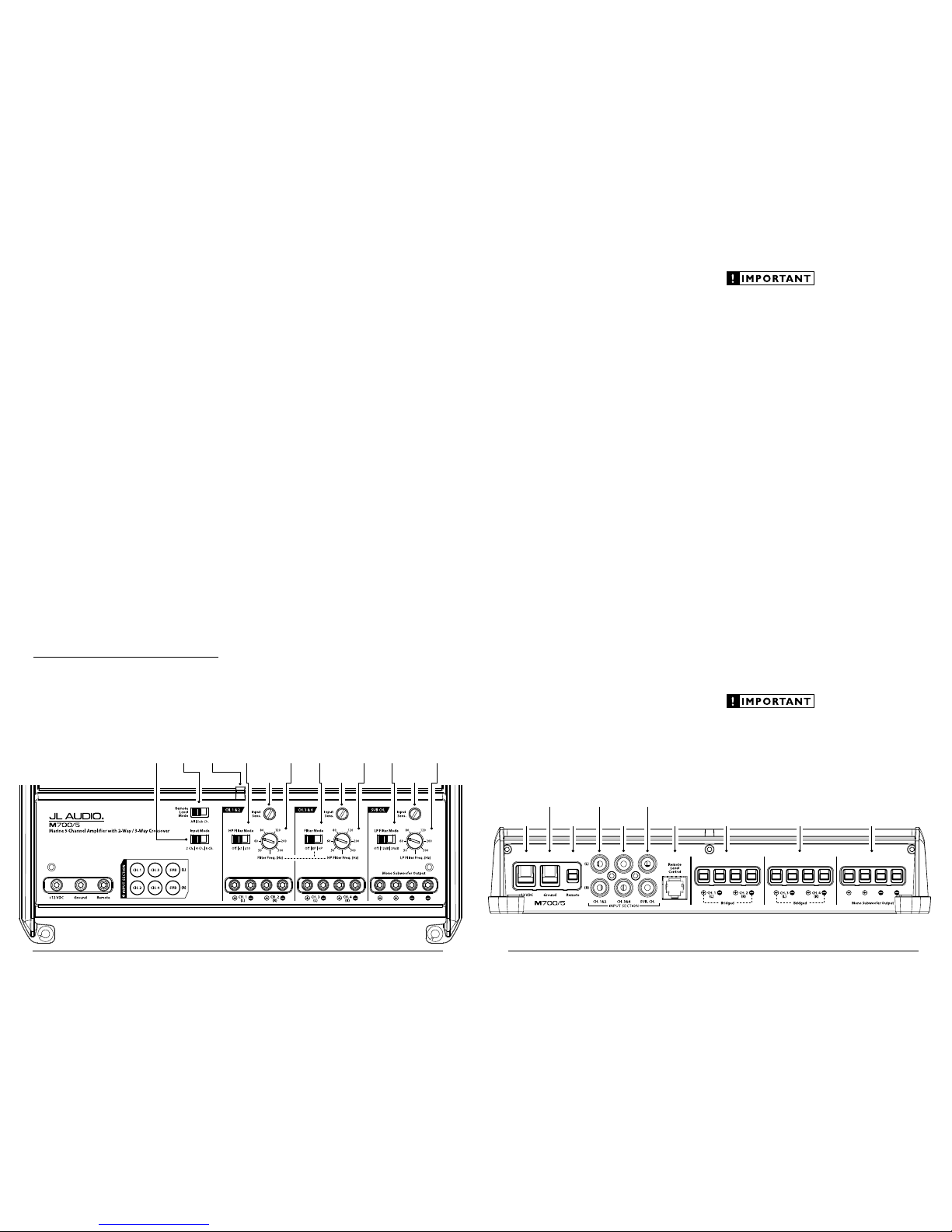
Status
LED
(pg. 11)
Ch. 1 & 2 Filter
Frequency
Selector
(pg. 8)
Ch. 1 & 2
Filter Mode
Selection
(pg. 8)
Ch. 1 & 2 Input
Sensitivity Control
(pg. 7)
Remote
Level Mode
Switch
(pg. 9)
Input
Mode
Switch
(pg. 7)
Ch. 3 & 4 Filter
Frequency
Selector
(pg. 8)
Ch. 3 & 4
Filter Mode
Selection
(pg. 8)
Ch. 3 & 4 Input
Sensitivity Control
(pg. 7)
Sub. Ch. Filter
Frequency
Selector
(pg. 8)
Sub. Ch.
Filter Mode
Selection
(pg. 8)
Sub. Ch. Input
Sensitivity Control
(pg. 7)
Remote Turn-On
Connector
(pg. 6)
Chassis Ground
Connector
(pg. 5)
Channels 1 & 2
Preamp Input Jacks
(pg. 7)
Subwoofer Ch.
Preamp Input Jacks
(pg. 7)
+12 V Power
Connector
(pg. 5)
Mono
Subwoofer Outputs
(pg. 10)
Channels 3 & 4
Speaker Outputs
(pg. 10)
Channels 1 & 2
Speaker Outputs
(pg. 10)
Jack for
Remote Level
Control Knob
(pg. 9)
Channels 3 & 4
Preamp Input Jacks
(pg. 7)

4 | JL Audio - M700/5 Owner’s Manual
5
POWER CONNECTIONS
Before installi ng the amplifier, disconnect t he
negative (ground) wire f rom the vessel’s batter y.
This will prevent ac cidental damage to t he system,
the vessel a nd your body during instal lation.
The M700/5’s “+12 V DC” and “Grou nd”
connections are desig ned to accept 4 AWG
power wi re. 4 AWG is the required wire size for
this amplif ier.
If you are install ing the M700/5 with other
amplif iers and wish to use a single main power
wire, use 2 AWG or 1/0 AWG main power wire
(depending on the overall c urrent demands of all
the ampli fiers in the system). This large power
wire should terminate into a fused distribution
block mounted as close to the a mplifiers as
possible (within 12 inches / 30cm of wi re length).
The fused output of the d istribution block wi ll
connect to t he M700/5 with 4 AWG power wire.
JL Audio ECS fused distr ibution blocks are
recommended (XD-FDBU-2 and XD-FDBU-4)
Note: Smaller AWG numbers mean bigger
wire and v ice-versa (1/0 AWG is the largest, 2
AWG is smal ler, then 4 AWG, then 8 AWG, etc.).
To connect the power wires to the a mplifier,
first back out the set screw on the top of t he
terminal block, using the suppl ied 2.5 mm hex
wrench. Strip 1/2 inch (12 mm) of insulation from
the end of each w ire and insert the bare wire i nto
the terminal block, seating it firmly so that no
bare wire is expose d. Whi le holding the wire in
place, tig hten the set s crew firmly, tak ing care not
to strip the head of the screw.
The ground connection should be made u sing
the same gau ge wire as t he power connection.
Any wires run th rough barriers must
be protected w ith a high qualit y rubber
grommet to prevent damage to t he
insulat ion of the wi re. Failu re to do so
may result in a d angerous short circu it.
Many vessels employ small (10 AWG - 6 AWG)
wire to conne ct the alternator’s positive
connection to the batter y. To prevent voltage
drops, this wire shou ld be upgraded to 4 AWG
when insta lling amplifier systems wit h main
fuse rati ngs above 60A.
It is common for the a lternator to be grounded
throug h its chassis. If the a lternator is not
grounded t hrough its chassis a nd instead employs
a small (10 AWG - 6 AWG) wire to connect to
ground, t his wire should al so be upgraded to 4
AWG when inst alling ampli fier systems wit h main
fuse rat ings above 60A.
FUSE REQUIREMENTS
It is absolutely vital that the mai n power
wire(s) to the amplifier(s) in the system be
fused w ithin 18 inches (45 cm) of the positive
battery post connec tion. The fuse value at each
power wire shou ld be high enough for all of the
equipment being run from t hat power wire. If
only the M700/5 is being ru n from that power
wire, we recommend a 60A fuse be used.
If fusing the amplifier near its power
connections (when more than one amp is being
run from t he main power wire), use a 60A fu se.
MAXI™ plast ic-body fuses are recommended.
PRODUCT DESCRIPTION
The JL Audio M70 0/5 is a five-channel,
system amplifier utilizing JL Audio NexD™ ultra-
high speed switching technology for its four main
channels and NexD™ high-speed switching for
its subwoofer channel. The NexD™ technologies
deliver outst anding fidelit y and efficiency.
The M700/5 can be operated w ith a wide
variet y of source units and system conf igurations.
TYPICAL INSTALLATION SEQUENCE
The followi ng represents the sequence for a
typical ampli fier installation, using an af termarket
source unit. Additional steps a nd different
procedures may be required in some applications.
If you have any questions, please contact you r
authorized JL Audio dea ler for assistance.
1) Di sconnect the negative batter y post
connection and secu re the disconnected cable
to prevent accidental re-connection during
insta llation. This step is not opt ional
2) Ru n 4 AWG power wire from the battery
location to t he amplif ier mounting location,
taki ng care to route it in such a way that it
will not be damaged and wi ll not inter fere
with vessel operation. Use 2 AWG or larger
power wire and a power distribution block if
additiona l amplifiers are being inst alled with
the M700/5.
3) Connect power wire to t he positive battery
post. Fuse the wire w ith an appropriate fus e
block (and connectors) within 18 inches (45
cm) wire length of the positive battery post.
This fus e is essential to protect t he vessel. Do
not instal l the fuse until t he power wire has
been secu rely connected to the ampl ifier.
4) Connect negative power wire to the negative
battery post. Use the same size power wire as
the wi re connected to t he “+12V ” connection
(minimum 4 AWG).
5) Run signal cables and remote turn- on wire
from the sou rce unit to t he amplifier
mounting location.
6) Run speaker cable f rom the subwoofer
system(s) to the ampli fier mounting locat ion.
7) Securely mount the amplif ier.
8) Connect t he positive and negative power
wires to t he amplifier. A fuse near the
amplif ier is not necessary i f the M600/6 is the
only device being run from the fused ma in
power wire. If the fused main power wire is
shared by the M600/6 and ot her amplifiers
or devices, fuse each amplifier/device
withi n 12 inches (30 cm) of wire length,
via a fused dist ribution block or multiple
individual fuse blocks/on-boa rd fuses.
9) Connect the remote turn-on wire
to the amplifier.
10) Connect the input cables to t he amplifier.
11) Con nect the speaker cables to t he amplifier.
12) Carefully review the amplifier’s control
setti ngs to make sure that they are set
according to the needs of t he system.
13) Install the power wire f use (60A for a
single M700/5) and reconnect t he negative
battery post terminal. Instal l the fuse (60A)
near the a mplifier (if applicable).
14) Turn on the sou rce unit at a low level
to double-check that the a mplifier is
config ured correctly. Resist t he temptation
to crank it up until you have verified the
control settings.
15) Ma ke necessary adjustments to t he input
sensitiv ity control s to obtain t he right
overall out put and the desired balance
in the system. See Appendix A (page 14)
for the recommended input sensit ivity
setting method.
16) Enjoy the fruits of your labor with your
favorite music.
6 | JL Audio - M700/5 Owner’s Manual
7
Input Voltage Range:
The M700/5’s input sections are desig ned to
accept signal voltage s from 100mV – 4V. This
will accommodate all prea mp level signals and
many spea ker level signals.
To use speaker-level sources, si mply splice the
speaker out put wires of the source unit onto a
pair of RCA plugs for each input pair. (or use
JL Audio part XD-CLRAIC2-SW) No “line
output converter” is needed in most cases.
If you find t hat the output cannot be reduced
suff iciently w ith a direct spea ker level signal
applied to the amplifier, you may use a “line
output converter” to reduce t he signal level.
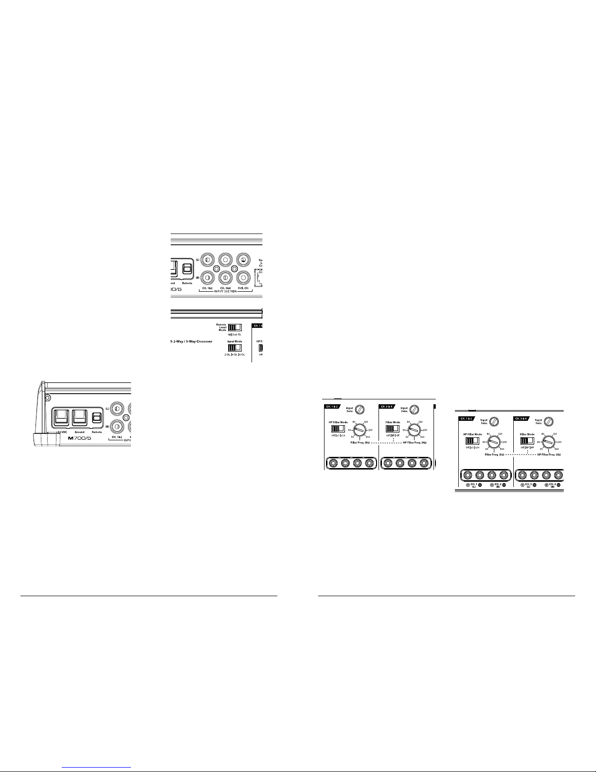
INPUT SENSITIVITY CONTROLS
The controls labeled “Input S ens.” located in
each channel section can be u sed to match the
source unit’s output voltage to the input stage of
each pair of amplif ier channels for max imum
clean output . Rotating the control clockwi se wil l
result in higher sensitivity (louder for a given
input voltage). Rotating the control counterclockwise will result i n lower sensitivity (quieter
for a given input volta ge.)
To properly set the ampli fier for maximum
clean output , please refer to Appendix A (page
14) in this manua l. After using this procedu re,
you can then adjust any or all “I nput Sens.”
levels downwa rd if thi s is require d to achieve t he
desired system bala nce.
Do not increase any “Input Sens.” se tting for
any channel(s) of any amplifier i n the system
beyond the ma ximum level established during
the procedure outlined i n Appendix A (page 14).
Doing so wi ll result in audible distortion and
possible spea ker damage.
FILTER CONTROLS
Most speakers are not designed to reproduc e
the full range of f requencies audible by the human
ear. For this reason, most sp eaker systems are
comprised of mu ltiple speakers, each dedicated
to reproducing a specif ic frequency range. Fi lters
are used to select which frequency r ange is sent to
each sect ion of a speaker system. T he division of
frequency r anges to different spe akers can be done
with passive filters (coils and /or capacitors bet ween
the ampli fier outputs and the speakers), which
are accept able and commonly used for f iltering
between m id-range speakers a nd tweeters. Filteri ng
between subwoofer systems and satellite spea ker
systems is b est done with active f ilters, which cut
off frequency content at the i nput to the amplifier.
Active filters are more stable tha n passive filters
and do not intro duce extraneous resistanc e, which
can degrade subwoofer per formance.
The active filter bu ilt into each channel section
of the M700/5 ca n be used to el iminate potentially
harmf ul and/or undesired frequencies from
maki ng their way through the amplifier sections
to the spea ker(s). This serve s to improve tonal
balance and to avoid distortion and possible
speaker failure. Correc t use of these fi lters can
substant ially increase t he longevity and fidelity of
your audio system.
1) “Filter Mode” Controls: The M700/5 employs
12dB per octave filters for each pair of main
channels (one high-pass f ilter for channels
1&2 and another high-pas s / bandpass filter
for channel s 3&4. The Subwoofer Channel
provides a low-pass filter w ith the option of
12dB or 24dB / octave slopes. Each of t hese
filters can be controlled or defeated completely
by way of the three-position “Filter Mode”
switches in each Channel Se ction:
TURN ON LEAD
The M700/5 uses a conventional +12V remote
turn-on le ad, ty pically controlled by the source
unit's remote turn-on output. The amplifier w ill
turn on when +12V is present at its “Remote”
input and turn off when +12V is switched off. If
a source unit does not have a dedicated remote
turn-on out put, the amplifier’s turn-on lead c an
be connected to +12V via a switch that derives
power from an ig nition-switched circ uit.
The M700/5’s “Remote” turn-on con nector is
designed to accept 18 AWG – 12 AWG wire. To
connect t he remote tur n-on wire to the amplifier,
first back out the set screw on the top of t he
terminal block, using the suppl ied 2.5mm hex
wrench. Strip 1/2 inch (12mm) of wire a nd insert
the bare w ire into the terminal block, se ating it
firm ly so that no bare wire is exposed . While
holding the wire in t he terminal, tig hten the set
screw firmly, tak ing care not to strip t he head of
the screw a nd making sure that the wi re (not the
insulat ion) is firmly gripped by the wi re clamp in
the terminal.
INPUT SECTION
The M700/5’s input section allows you to send
signals to the amplifier se ction through the use
of two, four or six differential-ba lanced inputs.
Input connections are via up to three pairs of
tradit ional RCA-type jack s.
If you wish to send six dis crete channels into
the M700/5, simply use all six inputs a nd set the
“Input Mode” switch in the “6 Ch.” position. The
amplif ier will automatic ally combine the Sub Ch.
input signa ls to mono.
If you prefer to use only four chan nels of input
into the M700/5, set the “Input Mode” switch in
the “4 Ch.” position and use t he Ch 1 & 2 and
Ch 3 & 4 Inputs. In this mode, the M700/5 w ill
derive its subwoofer channel signal f rom a sum
of all four i nput signals. The bas s will not fade
when the signal is faded by the head unit from
front to rear.
You may also choose to apply on ly two
channels of input to deliver signal to a ll five
amplif ier channels. To do this, set the “Input
Mode” switch to “2 Ch.” and use only the inputs
to channels 1 & 2. In this mode, Chan nel 3 will
operate wit h the Channel 1 signal a nd Channel
4 will operate with the Channel 2 signal. The
amplif ier will automatica lly combine the main
input signa ls to mono for the Subwoofer Cha nnel.
 Loading...