

JL Audio G6600 Owner's Manual
Thank you for purchasing a JL Audio amplifier for
your automotive sound system.
Your amplifier has been designed and manufactured to exacting
standards in order to ensure years of musical enjoyment in your vehicle.
For maximum performance, we highly recommend that you have
your new amplifier installed by an authorized JL Audio dealer. Your
authorized dealer has the training, expertise and installation equipment
to ensure optimum performance from this product. Should you
decide to install the amplifier yourself, please take the time
to read this manual thoroughly so as to familiarize yourself
with its installation requirements and setup procedures.
If you have any questions regarding the instructions in this
manual or any aspect of your amplifier’s operation, please contact your
authorized JL Audio dealer for assistance. If you need further assistance,
please call the JL Audio Technical Support Department
at (954) 443-1100 during business hours.
OWNER’S MANUAL

PLANNING YOUR INSTALLATION
It is important that you take the time to read
this m anual and t hat you plan out your
insta llation caref ully. The followi ng are some
considerat ions that you must t ake into account
when plan ning your ins tallation.
Cooling Efficiency Consid erations:
The outer shell of your JL Audio amplifier
is designed to remove heat from the amplifier
circuit ry. For optimum co oling performa nce,
this outer shell should be exposed to as large a
volume of air as possible. Enclosing the amplifier
in a small, poorly ventilated chamber can
lead to excessive heat build-up and degraded
performance. If an installation calls for an
enclosure around the amplifier, we recommend
that t his enclosure be ventilated with the aid
of a fan. In normal applications, fan-cooling
is not nece ssary.
Mounting t he amplifier upsi de down is
strongly discouraged.
If mounting the amplifier under a seat,
make su re there is at lea st 1 inch (2.5 c m) of
space above the amplif ier’s outer shel l to permit
proper coolin g.
Safety Considerations:
Your amplifier needs to be installed in a dry,
well-ventila ted environment a nd in a manner
which does not interfere with your vehicle’s safety
equipment (air bags, seat belt systems, ABS brake
systems, etc.). You should also take the time to
securely mount the amplifier so that it does not
come loose in the event of a collision or a sudden
jolt to the vehicle.
Stupid Mistakes to Avoid
• Check before drilling any holes in your vehicle
to make sure that you will not be drilling
throug h a gas tank , brake line, wiring har ness or
other v ital vehicle sys tem.
• Do not run system wiring outside or underneath
the vehic le. This is a n extremely da ngerous
practice which can result in severe damage to
your vehic le and person.
• Protect all system wires from sharp metal
edges and wear by carefully routing them,
tying them down and using grommets and
loom where appropriate .
• Do not mount the amplifier in the engine
compart ment, under the ve hicle, on the roof
or in a ny other area th at will exp ose the
amplifier circuitry to the elements.
PROTECT YOUR H EARING!
We value you as a long-term customer. For
that rea son, we urge you to pr actice restra int in
the oper ation of this produc t so as not to d amage
your hearing and that of others in your vehicle.
Studies have shown that cont inuous exposure to
high sound pressure levels can lead to permanent
(irrepara ble) hearing loss . This and a ll other
high-power a mplifiers ar e capable of producing
such hig h sound pressure le vels when connect ed
to a spea ker system. Plea se limit your continuous
exposu re to high volume le vels.
While driving, op erate your audio sy stem in
a manner that still allows you to hear necessary
noises to operate your vehicle safely (horns,
sirens, etc.).
SERIAL NUMBER
In the event that your amplifier requires
service or is ever stolen, you will need to have
a record of the product’s serial number. Please
take the time to enter that number in the space
provided be low. The serial nu mber can be fou nd
on the bottom panel of the amplifier and on the
amplifier packag ing.
Serial Number:
INSTALLATION APPLICATIONS
This amplifier is designed for operation in
vehicles with 12 volt, negative-ground electrical
systems. Use of this product in vehicles with
positive ground and/or voltages other than 12V
may result in damage to the product and will void
th e w arr ant y.
This product is not certified or approved for
use in aircraf t.
Do not att empt to “bridge” t he outputs of th is
amplif ier with the outputs of a second amplifier,
includin g an identical one.
Input Voltage
Selection
(pg. 6)
Channels 3 & 4
Preamp Input J acks
(pg. 6)
Power
Status
Indicator
(pg. 9)
Ch. 1 & 2 Filter
Frequency
Selector
(pg. 8)
Ch. 1 & 2 Input
Sensitivity
Control
(pg. 6)
Protection St atus
Indicator
(pg. 9)
Ch. 1 & 2
Filter Mode
Selection
(pg. 7)
Ch. 3 & 4
Filter Mode
Selection
(pg. 7)
Ch. 3 & 4
Input Sensitivit y
Control
(pg. 6)
Ch. 3 & 4
Filter Frequenc y
Selector
(pg. 8)
Channels 1 & 2
Preamp Input Jacks
(pg. 6)
Channels 5 & 6
Preamp Input Jacks
(pg. 6)
Bass Boost
On/Off Switch
(pg. 8)
Jack for
Remote Bass
Control Knob
(pg. 8)
Ch. 5 & 6
Input Sensitivity
Control
(pg. 6)
Ch. 5 & 6
Filter Frequency
Selector
(pg. 8)
Ch. 5 & 6
Filter Mode
Selection
(pg. 7)
Input Mode
Switch
(pg. 6)
Remote Turn-On
Connector
(pg. 5)
Chassis Ground
Connector
(pg. 5)
+12 V Power
Connector
(pg. 4)
Channels 5 & 6
Speaker Outputs
(pg. 8)
Channels 3 & 4
Speaker Outputs
(pg. 8)
Channels 1 & 2
Speaker Outputs
(pg. 8)
2 JL AUDIO G6600 JL AUDIO G6600 3
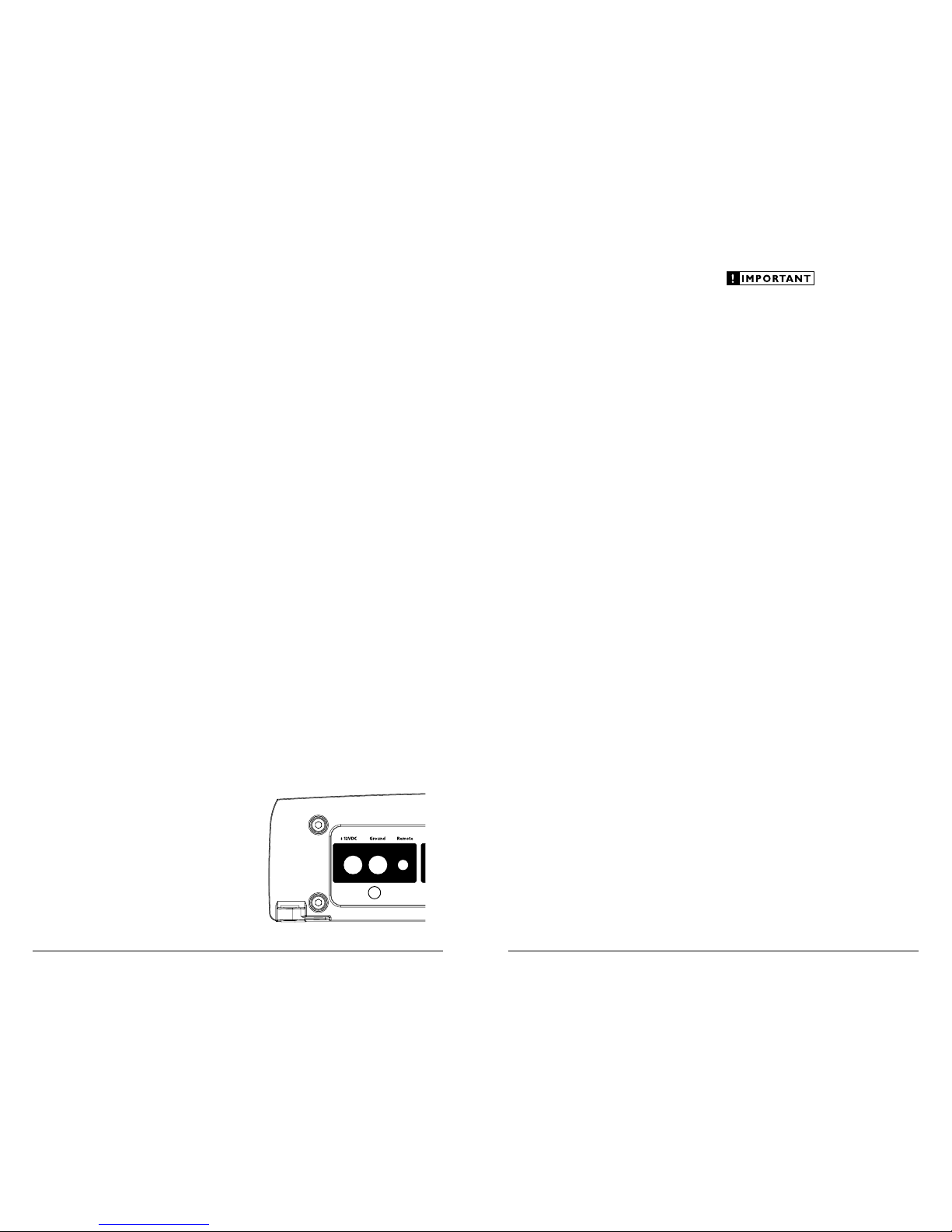
The G6 600’s “+12 V DC ” and “Ground ”
connect ions are designed to accept 4 AWG
power w ire. 4 AWG is a minimum power wire
size for this amplifier.
If you are installing the G6600 with other
amplif iers and wish to use a single main power
wire, use 2 AWG or 1/0 AWG main power wire
(depending on the overall current demands of all
the amplifiers in the system). This 2 AWG or
1/0 AWG power wire shoul d terminate into
a distribution block mounted as close to the
amplifiers as possible and should connect to the
G6600 with 4 AWG power wire.
Note: Smaller AWG numbers mean bigger
wire a nd vice-versa (1/0 AWG is the large st, 2
AWG is smaller, then 4 AWG, then 8 AWG, etc.).
To connect the power wires to the amplifier,
first back out the set screw on the top of the
terminal block, using the supplied 2.5 mm hex
wrench. S trip 1/2 inch (12 mm) of in sulation from
the end of each wire and insert the bare wire into
the terminal block, seating it firmly so that no
bare wire is exposed. While holding the wire in
place, tighten the set screw firmly, taking care not
to strip the head of the screw.
The ground connection should be made using
the sa me gauge wire as t he power connection
and should be kept as short as possible, while
accessing a solid piece of sheet metal in the
vehicle. The surface of the sheet metal should
be sande d at the contact p oint to create a clea n,
metal-to-me tal connection between the chassis
and the termination of t he ground wire. For
optimal g rounding, we recommend the u se of a
JL Audio ECS ma ster ground lug (XB-MGLU).
Alternat ively, a sheet metal screw or bolt can be
used with a star washer.
Any wires run through metal barriers (such
as firewalls), must be protected with a high
quality rubber grommet to prevent damage to the
insulation of the wire. Failure to do so may result
in a dangerous short circuit.
Many vehicles employ small (10 AWG -
6 AWG) wire to ground the battery to the
vehicle chassis and to connect the alternator's
positive con nection to the bat tery. To prevent
voltage drops, these wires should be upgr aded
to 4 AWG when installing amplif ier systems
with ma in fuse rati ngs above 60A.
FUSE REQUIREMENTS
It is absolutely vital that the main power wire(s)
to the a mplifier(s) in the s ystem be fuse d within
18 inches (45 cm) of the positive bat tery post
connection. The fuse value at each power wire
should be high enough for a ll of the equ ipment
being r un from that p ower wir e. If only the
G660 0 is being ru n from that power w ire, we
recommend a 60A fuse be used. AFS (mini blade
fuse), AGU (big glass fuse) or MaxiFuse™ (big
plastic-b ody fuse) typ es are recommended .
No fuse is required or rec ommended direct ly
before the amplifier power connection. If one is
desired, we recommend the u se of a 60A fus e.
TURNON LEAD
The G6600 uses a conventional +12V remote
turn-on lead, typically controlled by the source
unit's remote turn-on output. The amplifier will
turn on when +12V is prese nt at its “Remote”
input and turn off when +12V is switched off. If
a source u nit does not have a dedicated remote
turn-on output, the amplifier’s turn-on lead can
be connec ted to +12V via a switch that derives
power from an ignition-switched circuit.
The G6 600’s “Remote” turn-on con nector is
designed to accept 18 AWG – 12 AWG wire. To
connect the remote turn- on wire to the a mplifier,
first back out the set screw on the top of the
terminal block, using the supplied 2.5mm hex
wrench. Strip 1/2 inch (12mm) of wire and insert
the bar e wire into the terminal bloc k, seating it
firmly so that no bare wire is exposed. While
holding t he wire in t he terminal, tighten the se t
screw firmly, taking care not to strip the head of
the screw and making sure that the wire (not the
insulat ion) is firmly gripped by the set screw.
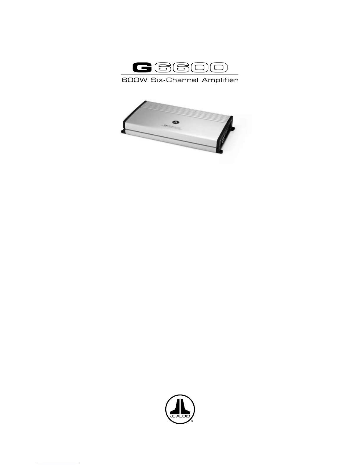
PRODUCT DESCRIPTION
The JL Audio G6600 is a six-channel,
full-range audio amplifier utilizing patented
Absolute Symmetry™ Class A/B technology
for all channels.
The G6600 can be operated with a wide variety
of source u nits and sys tem configur ations.
TYPICAL INSTALLATION SEQUENCE
The following represents the sequence
for a ty pical amplif ier instal lation, using a n
after market source u nit or OEM Interfa ce
processor (like the CleanSweep CL441dsp).
Additional steps and different procedures may
be required in some applications. If you have
any questions, please contact your authorized
JL Audio dea ler for assista nce.
1) Disconnec t the negative b attery post
connection and secure the disconnected cable
to prevent accidental re-connection during
insta llation. This step is not optional.
2) Run power wire (minimum 8 AWG) from the
battery location to the amplifier mounting
location, taking ca re to route it in such a
way that it will not be damaged and will not
interfere w ith vehicle oper ation. Use 4 AWG
or larger power wire and a power distribution
block if additional amplifiers are being
installed with the G6600.
3) Con nect power wire t o the positive bat tery
post. Fuse the wire with an appropriate fuse
block (and con nectors) within 18 inches (45
cm) wire length of the positive battery post.
This fuse is essential to protect the vehicle.
Do not install the fuse until the power wire
has been securely connected to the amplifier.
4) Run signal cables and remote turn-on wire
from the source unit to t he final a mplifier
mounting location.
5) Run spea ker cables from the speaker s ystems
to the a mplifier mount ing location.
6) Find a good, solid metal grounding point
close to t he amplifier and connect t he
negative power wire to it usi ng appropriate
hardware (use of the JL Audio ECS master
ground lug, X B-MGLU is recommended).
Use the s ame size power w ire as the w ire
connecte d to the “+12V DC ” connection
(minimum 8 AWG), no longer than 36 inches
(90 cm) from the amplifier to the ground
connection point. In some vehicles, it may be
necessary to upgrade the battery ground wire.
(See page 5 for important notice).
7) S ecurely mount the amplifier.
8) Connect the positive a nd negative power
wires to the amplifier. A fuse near the
amplif ier is not necess ary.
9) Connect the remote turn-on wire
to the a mplifier.
10) Con nect the input ca bles to the ampl ifier.
11) Connect t he speaker cab les to the ampli fier.
12) Carefully review the amplifier’s control
settings to make sure that they are set
according to the needs of the system.
13) Instal l the power wire fuse (60A for a
single G6600) and reconnect the negative
battery post terminal.
14) Turn on the source un it at a low level
to double-check that the amplifier is
config ured correct ly. Resist t he temptation
to crank it up until you have verified the
control set tings.
15) Make necessary adjustments to the input
sensitivity controls to obtain the right
overall output and the de sired balance
in the system. See Appendix A (page 14)
for the recommended input sensitivity
setting method.
16) Enjoy the fruits of your labor with your
favorite music .
POWER CONNECTIONS
Before installing the amplifier, disconnect the
negative (ground) wire from the vehicle’s battery.
This will prevent accidental damage to the system,
the vehic le and your body during inst allation.
4 JL AUDIO G6600 JL AUDIO G6600 5
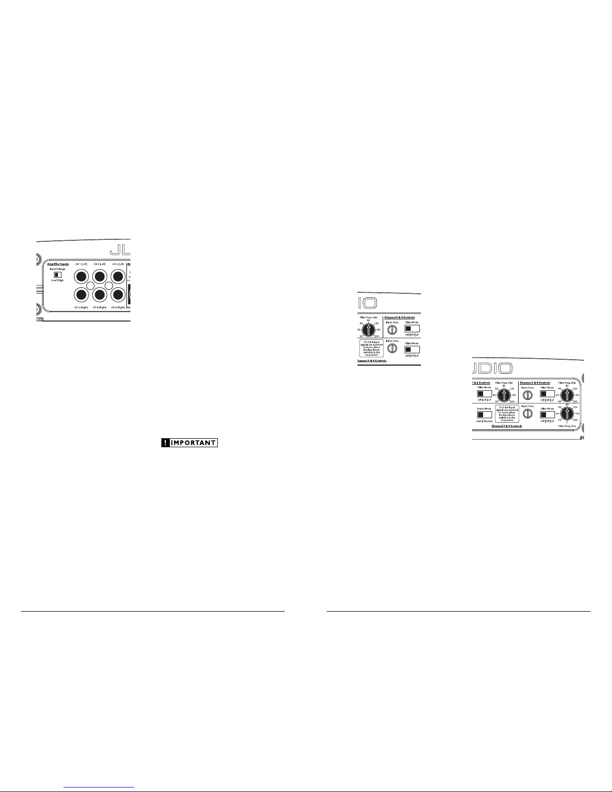
INPUT SENSITIVITY CONTROLS
Once the appropriate “Input Voltage” range
has been selected, the controls labeled “Input
Sens.” located in e ach “Channel Control s”
section can be used to match the source unit’s
output volta ge to the input sta ge of each pair of
amplifier channels for maximum clean output.
Rotating the control clockwise will result in
higher sensitivity (louder for a given input
voltage). Rotating the control counter-clockwise
will result in lower sensitivity (quieter for a given
input voltage.)
To properly set the amplifier for maximum
clean out put, please refer to Appendix A (page
14) in this manual. After using this procedure,
you can then adjust any or all “Input Sens .”
levels downward if this is required to achieve the
desired system balance.
Do not increase any “Input Sens.” setting for
any channel(s) of any amplifier in the system
beyond the maximum level established duri ng
the procedure outlined in Appendix A (page
14). Doing so will result in audible distortion
and possi ble speaker dam age.
FILTER CONTROLS
Most spea kers are not desi gned to reproduce
the full range of frequencies audible by the
human e ar. For this reas on, most speaker
systems are comprised of multiple speakers, each
dedicated to reproducing a specific frequency
range. Fi lters are used to select which f requency
range is sent to each section of a speaker system.
The division of frequency ranges to different
speakers can be done with passive filters (coils
and/or capacitors between the amplifier outputs
and the speakers), which are acceptable and
commonly used for filter ing between m idrange speakers and tweeters. Filtering between
subwoofer systems and satellite speaker systems
is best done with active filters, which cut off
frequency content at the input to the amplifier.
Active filters are more stable than passive filters
and do not introduce extr aneous resista nce,
which ca n degrade subwoofer performance.
The active filter built into each channel section
of the G6600 can be used to eliminate potentially
harmful and/or undesired frequencies from
making their way through the amplifier sections
to the speaker(s). This serves to improve tonal
balanc e and to avoid dis tortion and pos sible
speaker failure. Correct use of these filters can
substantially increase the longevity and fidelity of
your audio system.
1) “Filte r Mode” Control: T he G6600 employs a
12dB per octave filter for each pair of channels
(one filter for channels 1&2, another filter for
channels 3&4 and a third filter for channels
5&6). Each of these filters can be configured
independently into one of two filter types
or defeated completely by way of th e threeposition “Fi lter Mode” switc hes:
“Of f ”: Defeats the filter completely, allowing
the full range of frequencies present at the
inputs to feed the amplifier. This is useful
for systems utilizing outboard crossovers or
requiring full-range reproduction from one or
more of the G6600’s channel pairs.
INPUT SECTION
The G6600’s input section allows you to send
signals to the amplifier section through the use of
two, four or six differe ntial-b alanced inputs .
Input connec tions are via three pairs of
tradit ional RCA-type ja cks.
If you w ish to send six d iscrete channe ls into
the G6600, simply use all six inputs and set the
“Input Mode” s witch in the “Cha nnel 5 & 6
Controls ” section to “Discre te”.
If you wish to feed all six channels by using
only four channels of full-range input, set the
“Input Mode” s witch in the “Cha nnel 5 & 6
Controls ” section to “Sum” and use only the
inputs to c hannels 1, 2, 3 & 4.
If you wish to feed all six channels by using
two cha nnels of ful l-range input and t wo
channels of low-frequency input (subwoofer
output from the source un it), set th e “Input
Mode” swit ch in the “Chan nel 5 & 6 Controls”
section to “Discrete”. It will be necessary to split
the full-range signals with y-adaptors and feed
these signals into the inputs to channels 1, 2, 3 &
4. The dedicated subwoofer signal should be sent
to chan nels 5 & 6.
If you wish to use only two channels of input
to deliver signal to all six amplifier channels,
it will be necessary to split the two signals with
y-adaptors a nd feed these sig nals into the inputs
to chan nels 1, 2, 3 & 4. S et the “Input Mode”
switch i n the “Channel 5 & 6 Controls”
section to “Sum” and use only the inputs
to chan nels 1, 2, 3 & 4.
Input Voltage Range:
A wide r ange of signal input voltages can
be accommodated by the G6600’s CH 1&2 and
CH 3&4 input sections (200mV – 8V). Th is
wide range is split up into two sub-ranges,
accessible via a switch located to the left of the
Input Conne ctors.
The “Low ” position on t he “Input Voltage”
switch s elects an input sensitivity r ange between
200mV and 2V. This me ans that the “Input
Sens.” rotary control will operate within that
voltage window. If you are using an aftermarket
source u nit or an OEM inte rface processor with
conventional preamp-level outputs, this is most
likely the position th at you will us e.
The “High” position on t he “Input Voltage”
switch s elects an input sensitivity r ange between
800mV and 8V. This is useful for certain highoutput prea mp level signals as well as spe akerlevel output from source units and
small amplifiers.
To use speaker-level sources, splice the speaker
output wires of the source unit or small amplifier
onto a pair of RCA plugs for each input pair.
No line out put converter is nee ded in most ca ses.
The CH 5& 6 input section is designed to
accept on ly line-level sig nals and may cl ip
(distort) if high-level signa ls are applied to it.
The output of the amplifier will decrea se for
a given input voltage when the “Input Range”
switch is placed in the “H igh” position.
Conversely, the output will be h igher with the
switch in the “Low” position. Wh ile this may
sound counte r-intuitive, it is c onsistent with
the desc riptions above.
6 JL AUDIO G6600 JL AUDIO G6600 7
 Loading...