

Page 1
Owner’s Manual / Manual del Propietario
Page 2

IMPORTANT SAFETY INSTRUCTIONS
WARNING: TO REDUCE THE RISK OF FIRE OR ELECTRIC SHOCK,
DO NOT EXPOSE THIS PRODUCT TO RAIN OR MOISTURE.
CAUTION
RISK OF ELECTRIC SHOCK
DO NOT OPEN
CAUTION: TO REDUCE THE RISK OF ELECTRIC SHOCK, DO NOT REMOVE
AMP PANEL OR SPEAKER. NO USER SERVICEABLE PARTS INSIDE. REFER
SERVICING TO QUALIFIED PERSONNEL.
1) Read the Instructions — All safety and operating instructions should be
read before the subwoofer is operated.
2) Retain the Instructions — e safety and operating instructions should be
retained for future reference.
3) Heed Warnings — All warnings on the subwoofer and in the operating
instructions should be followed.
e lightning ash with arrowhead
symbol, within an equilateral triangle, is
intended to alert the user to the presence
of uninsulated “dangerous voltage” within
the product’s enclosure that may be of
sucient magnitude to constitute a risk of
electric shock to persons.
e exclamation point within an
equilateral triangle is intended to alert the
user to the presence of important operating
and maintenance instructions in the
literature accompanying the product.
4) Follow Instructions — All operating and use instructions should
be followed.
5) Water and Moisture — e subwoofer should NOT be used near water – for
example, near a bathtub, washbowl, sink, laundry tub, in a wet basement,
near a swimming pool, etc.
6) Ventilation — e subwoofer should be situated so that its location or
position does not interfere with its proper ventilation. For example, the
subwoofer should not be situated on a bed, sofa, rug, or similar surface
that may block airow over the heatsink ns. If placing the subwoofer in
a “built-in” installation, ensure that airow to the heat sink at the rear of
the subwoofer is not impeded. Do not cover the subwoofer heatsink with
tablecloths, curtains, etc.
9) Heat and Flames — e subwoofer should be situated away from heat
sources such as radiators, heat registers, stoves, replaces, or other devices
which produce heat. Do not place candles on top of or near the subwoofer.
10) Power sources — e subwoofer should only be connected to a power supply of
the type described in the operating instructions or as marked on the subwoofer.
11) Power Cord Protection — Power-supply cords should be routed so that they
are not likely to be walked on or pinched by items placed upon or against
them, paying particular attention to cords at plugs, convenience receptacles,
and the point where they exit the subwoofer.
| Fathom v2Page 2
Page 3
12) Cleaning — e subwoofer should be cleaned only as recommended in the
operating instructions.
13) Nonuse Periods — e power cord of the subwoofer should be unplugged
from the outlet when the subwoofer is le unused for long periods of time.
14) Lightning and Power Surges — We recommend that you disconnect the
subwoofer from the electrical outlet during electrical storms and/or recurring
power interruptions to prevent damage due to power surges.
15) Object or Liquid Entry — Care should be taken so that objects do not fall
into and liquids are not spilled onto the subwoofer enclosure. Do not expose
the subwoofer to dripping or splashing from liquids. Do not place objects
lled with liquids on top of, or near the subwoofer. For example: ower vases,
beverages, liquid-fueled lamps, etc.
16) Damage Requiring Service — e subwoofer should be serviced by qualied
service personnel when:
a. the power-supply cord or plug has been damaged
b. objects have fallen or liquid has been spilled into the subwoofer
c. the subwoofer has been exposed to rain
d. the subwoofer does not appear to operate normally or exhibits a marked
change in performance
e. the subwoofer has been dropped or the cabinet has been damaged
f. the subwoofer driver’s cone and/or suspension has been
physically damaged
ENGLISH
WARNING
17) Servicing — e user should not attempt to service the subwoofer beyond
what is described in the operating instructions. All other servicing should be
referred to qualied service personnel.
18) Overloading — Do not overload wall outlets, extension cords, or outlet strips
as this can result in a risk of re or electric shock.
19) Grounding — is subwoofer is supplied with a three-prong, grounded
power cord. Precautions should be taken so that the grounding means of the
subwoofer are not defeated. Defeating the grounding prong on the subwoofer
power cord could increase the risk of electric shock and could result in
permanent damage to the subwoofer’s electronics.
THIS SUBWOOFER IS CAPABLE OF PRODUCING VERY HIGH SOUND
PRESSURE LEVELS. PLEASE EXERCISE RESTRAINT IN ITS OPERATION TO
PROTECT YOUR HEARING FROM PERMANENT DAMAGE.
Page 3 | Fathom v2
Page 4

FCC COMPLIANCE STATEMENT
NOTE: is equipment has been tested and found to comply with the limits of Part 15 of the FCC
Rules. ese limits are designed to provide reasonable protection against harmful interference in
a residential installation. is equipment generates, uses and can radiate radio frequency energ y
and, if not installed in accordance with the instructions, may cause harmful interference to radio
communications. However, there is no guarantee that interference will not occur in a particular
installation. If this equipment does cause harmful interference to radio or television reception,
which can be determined by turning the equipment o and on, the user is encouraged to try to
correct the interference by one or more of the following measures:
- Reorient or relocate the receiving antenna.
- Increase the separation between the equipment and receiver.
- Connect the equipment into an outlet on a circuit dierent from that to which the
receiver is connected.
- Consult the dealer or an experienced radio/TV technician for help.
TABLE OF CONTENTS
Important Safety Instructions: ......................................... 2-3
Introduction:. . . . . . . . . . . . . . . . . . . . . . . . . . . . . . . . . . . . . . . . . . . . . . . . . . . . . . . . . . . 4
Product Overview: ...................................................... 5
Placing your Fathom v2 in Your Listening Room: ........................ 6-10
Unpacking your Fathom v2: ............................................. 11
Front Control Panel Layout: ............................................. 12
Rear Control and Connector Panel Layout: .............................12-13
Front Panel Controls in Detail: ........................................14-17
Connecting your Fathom v2(s): ........................................18-25
Recommended Setup Procedure: ......................................26-30
Frequently Asked Questions: ............................................ 31
Cleaning Your Fathom v2: ...............................................31
Troubleshooting: ....................................................32-33
Limited Warranty / Service Information: ................................. 35
Specications: ......................................................... 36
INTRODUCTION
Congratulations on your purchase of a JL Audio Fathom v2 powered subwoofer
system. is product has been critically engineered to deliver exceptional
performance in your home theater or audio system for many years to come.
As a company, we are intensely committed to core research into
high-performance loudspeaker and amplier technologies. JL Audio’s longexcursion subwoofer driver designs are widely considered as reference standards for
linear behavior and high output. We have also focused our eorts to create powerful
amplier and signal-processing technologies specically aimed at delivering
exceptional low-frequency performance. Your Fathom v2 combines these core
disciplines within a compact, beautifully craed package to deliver an unparalleled
listening experience.
JL AUDIO TECHNOLOGIES INCLUDED
IN FATHOM V2 SUBWOOFERS
DMA-Optimized Motor System
DMA is JL Audio’s proprietary Dynamic
Motor Analysis system aimed at
improving dynamic motor behavior. As a
result of DMA optimization, loudspeaker
motors remain linear in force over an
extreme range of excursion and also
maintain a highly stable xed magnetic
eld over a wide power range. is leads
to vastly reduced distortion and faithfully
reproduced transients... or put simply:
tight, clean, articulate bass.
OverRoll™ Surround
(U.S. Patent #5,687,247 and #5,949,898)
e OverRoll™ surround spans over
the driver’s mounting ange, utilizing
available diameter wasted in conventional
speakers. is allows the use of the wider
roll necessary to control high-excursions
without sacricing precious cone area.
W-Cone™ (U.S. Patent #6,496,590)
e W-Cone™ is a unit-body cone
assembly that delivers astonishing cone
stiness with minimal mass.
Floating-Cone™ Attach Method
(U.S. Patent #6,501,844)
is assembly technique ensures proper
surround geometry in the assembled
speaker for better excursion control and
dynamic voice coil alignment.
Plateau-Reinforced Spider Attachment
(U.S. Patent #6,118,884)
is high-integrity suspension attachment
relieves stress from the spider material at
high-excursions for enhanced reliability.
Elevated Frame Cooling Technology
(U.S. Patent #6,219,431 and #6,229,902)
Delivers cool air, through slots directly
above the top-plate, to the voice coil of the
speaker. is enhances power handling
and sound quality by minimizing
dynamic parameter shis and power
compression.
Radially Cross-Drilled Pole Piece
(U.S. Patent #6,243,479)
is innovative venting system greatly
enhances thermal dissipation and power
handling by directing air ow onto the
voice coil former, working in conjunction
with the Elevated Frame technology.
High-Damping Feedback Circuit
(U.S. Patent #6,441,685)
is proprietary, discrete control circuit
design allows our Class D switching
ampliers to maintain an excellent
damping factor for improved transient
behavior and delity.
| Fathom v2Page 4
Page 5

We sincerely thank you for your purchase and invite you to read this
manual thoroughly in order to achieve the highest level of performance with
your Fathom v2 subwoofer system. Enjoy.
PRODUCT OVERVIEW
JL Audio Fathom v2 subwoofers combine a state-of-the-art
JLAudio subwoofer driver and electronics/amplier package within
a highly optimized enclosure to deliver an exceptional listening
experience in your home theater or home audio system.
e subwoofer driver in your Fathom v2 subwoofer system is capable of
outstanding linear excursion without distress or audible distortion. is
reference-quality driver enables your Fathom v2 to reproduce powerful
low-frequency events with stunning impact and unprecedented accuracy.
Derived from JL Audio’s legendary W7 design platform, the Fathom v2
drivers oer prodigious peak-to-peak excursion capabilities to comfortably
handle the dynamics of the most demanding program material.
To get the most from this long excursion driver platform, a tremendous
amount of controlled power is needed. Our electronics engineering team
conducted an intense analysis of typical program material and its dynamic
demands in order to balance current draw and actual output power requirements
relative to the system’s impedance characteristics. Aer careful study, precisely
engineered switching ampliers employing patented feedback technology were
created to take full advantage of each driver’s full excursion envelope. Compared
to their predecessors, Fathom v2’s have been improved with all new digital
signal processing and a 20% increase in amplier power, further enhancing their
outstanding dynamic capabilities.
e beautiful cabinet enclosing the workings of your Fathom v2 is also the
result of careful engineering. To contain the pressures created by the Fathom v2
driver, we utilized solid, CNC-cut, MDF material with extensive internal bracing
features and advanced assembly techniques.
Your listening room is the other enclosure that aects the way your bass will
sound. All rooms create a specic sonic signature, which must be eectively
managed to achieve well-balanced low frequency performance. To help properly
integrate your subwoofers with your room’s acoustics, all Fathom v2 subwoofers
employ a powerful, Digital Automatic Room Optimization (D.A.R.O.) system.
is system deploys eighteen bands of digital equalization to tame room
acoustics and deliver spine-tingling sub-bass accuracy.
As you can see from this brief introduction, Fathom v2 subwoofer systems
employ many advanced technologies. e contents of this manual will explain the
features, guide you through the setup and tuning of your Fathom v2 subwoofer and
help you achieve your ultimate low-frequency listening experience.
ENGLISH
IMPORTANT
If you require assistance, we urge you to contact your authorized
JL Audio retailer for expert setup advice and service.
IMPORTANT! IT IS A VERY GOOD IDEA TO READ THE NEXT SECTION BEFORE
UNPACKING YOUR FATHOM v2. UNPACKING THE SUBWOOFER NEAR ITS
FINAL LOCATION IS RECOMMENDED.
Page 5 | Fathom v2
Page 6

PLACING YOUR FATHOM v2 IN YOUR LISTENING ROOM:
Your listening room or theater is an integral part of your sound reproduction
system. e physical dimensions of the room and its furnishings, materials, doors
and windows play an important role in dening how your system sounds.
When you place a sound source in an enclosed rectangular space, “standing
waves” are created, resulting from the relationship between the sound’s
wavelength and your room’s dimensions. In other words, standing waves result
from sound energy that is trapped in the room as it bounces back and forth
between opposing walls. Standing waves in the room create acoustic peaks and
dips where the sound is either louder or soer, based solely on your physical
position in the room. Energy also “builds up” at the room’s boundaries, creating
exaggerated bass response at certain frequencies. ese fundamental room
resonances are called room “modes.”
e moral of this mode story is to try and avoid seating positions in standing
wave peak or dip regions. It is highly recommended that you place your listening
chairs in areas where modal peaks and dips are moderate and do not reinforce
one another. e two most obvious areas to avoid are those near the exact center
of the room and those close to any of the room’s walls.
Just as your listening seat can be in a peak or dip region, so can your
subwoofer. When placed in a room corner, a subwoofer maximally excites the
room’s mode structure, creating the strongest output with the fewest dips. When
the subwoofer is pulled away from a corner or wall, the room modes are excited
less, which can alter the sound at your listening seat.
Be sure to experiment with both your listening seat position and subwoofer
position to nd the best solution. Careful experimentation usually leads to a
superior sounding system. Use our setup suggestions (illustrated on the opposing
page and the following pages) to get you started.
If you cannot avoid placing your sofa against the back wall, or your
subwoofer in a less than optimal position, your Fathom v2’s Digital Automatic
Room Optimization (D.A.R.O.) System can dramatically improve
these less-than-ideal situations.
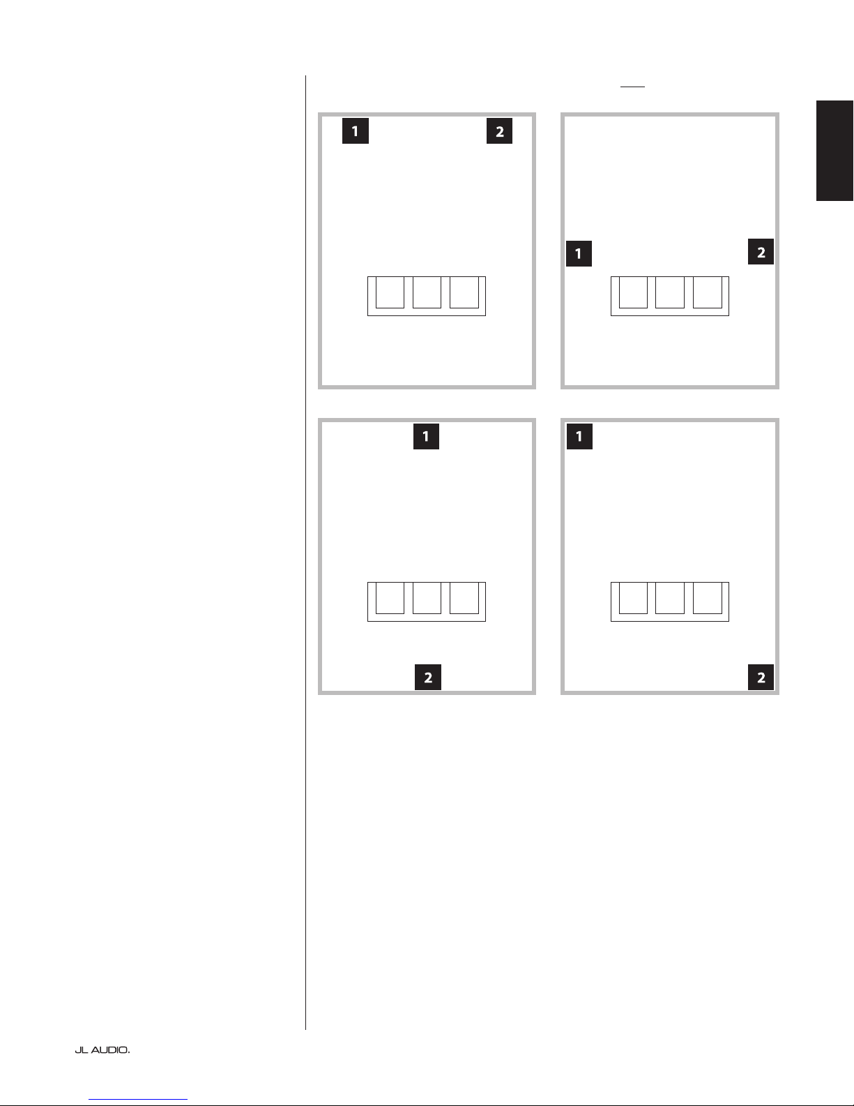
We recommend that you begin by placing your Fathom v2 in the front
of the room, near the front le or right speaker. Placing it directly in the
front corner of the room will produce the maximum number of peaks and
the minimum number of dips in the bass response. is can be advantageous
because the Fathom v2’s D.A.R.O. system can correct the resulting peaks very
eectively, whereas dips in response cannot be corrected via equalization. Dips in
response can only be minimized via careful subwoofer and listener placement.
Placing the Fathom v2 near solid walls will reinforce bass response and
pulling it away from solid walls will decrease bass. Increasing the distance
between the subwoofer and the walls may help to smooth upper bass response in
some rooms.
We recommend that you avoid placing the Fathom v2 near windows to prevent
rattling and sound transmission to the outside world.
If you are planning to install your Fathom
v2 inside a cabinet, please refer to the
guidelines on page 8.
| Fathom v2Page 6
Page 7
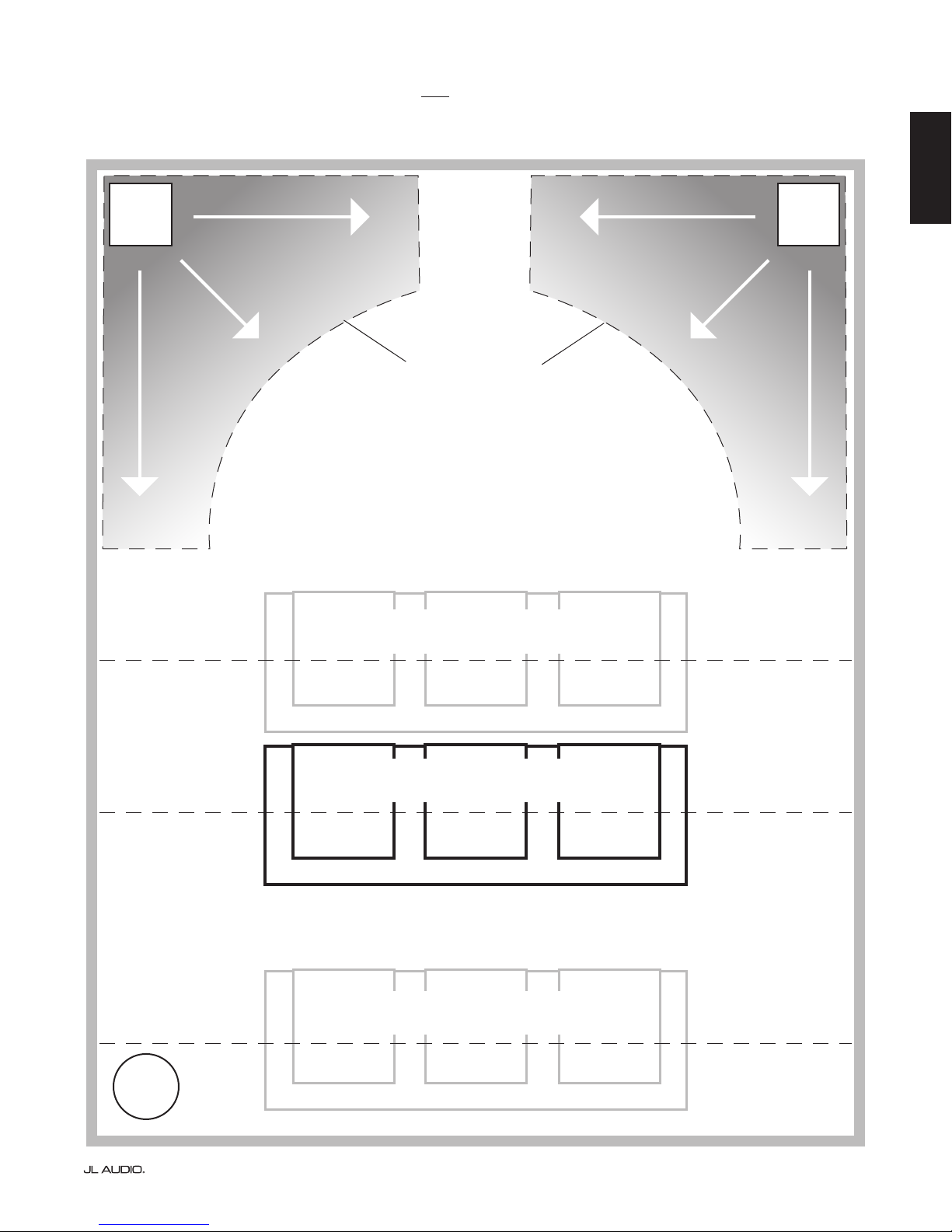
Recommended Subwoofer Placement Options for One Fathom v2
MORE INTENSE
SMOOTHER
SMOOTHER
SMOOTHER
RECOMMENDED
SUBWOOFER
PLACEMENT
ZONES
(For Single Subwoofer)
MORE INTENSE
ENGLISH
SMOOTHER
SMOOTHER
SMOOTHER
COMPROMISED SEATING POSITIONS
(Results in weaker, uneven bass performance)
BEST SEATING POSITIONS
(Most accurate bass performance)
COMPROMISED SEATING POSITIONS
(More intense, but less accurate bass performance)
CENTERLINE OF ROOM
APPROX. 1/3 OF TOTAL ROOM
LENGTH AWAY FROM BACK WALL
CLOSE TO BACK WALL OF ROOM
WORST
SEAT
Page 7 | Fathom v2
Page 8
SPECIAL CONSIDERATIONS FOR BUILT-IN INSTALLATIONS
Fathom v2 subwoofers are designed to be “built-in” friendly. All typically
needed controls are located on the front panel above the woofer. A Fathom v2 can
be easily integrated into custom cabinetry by following a few simple guidelines.
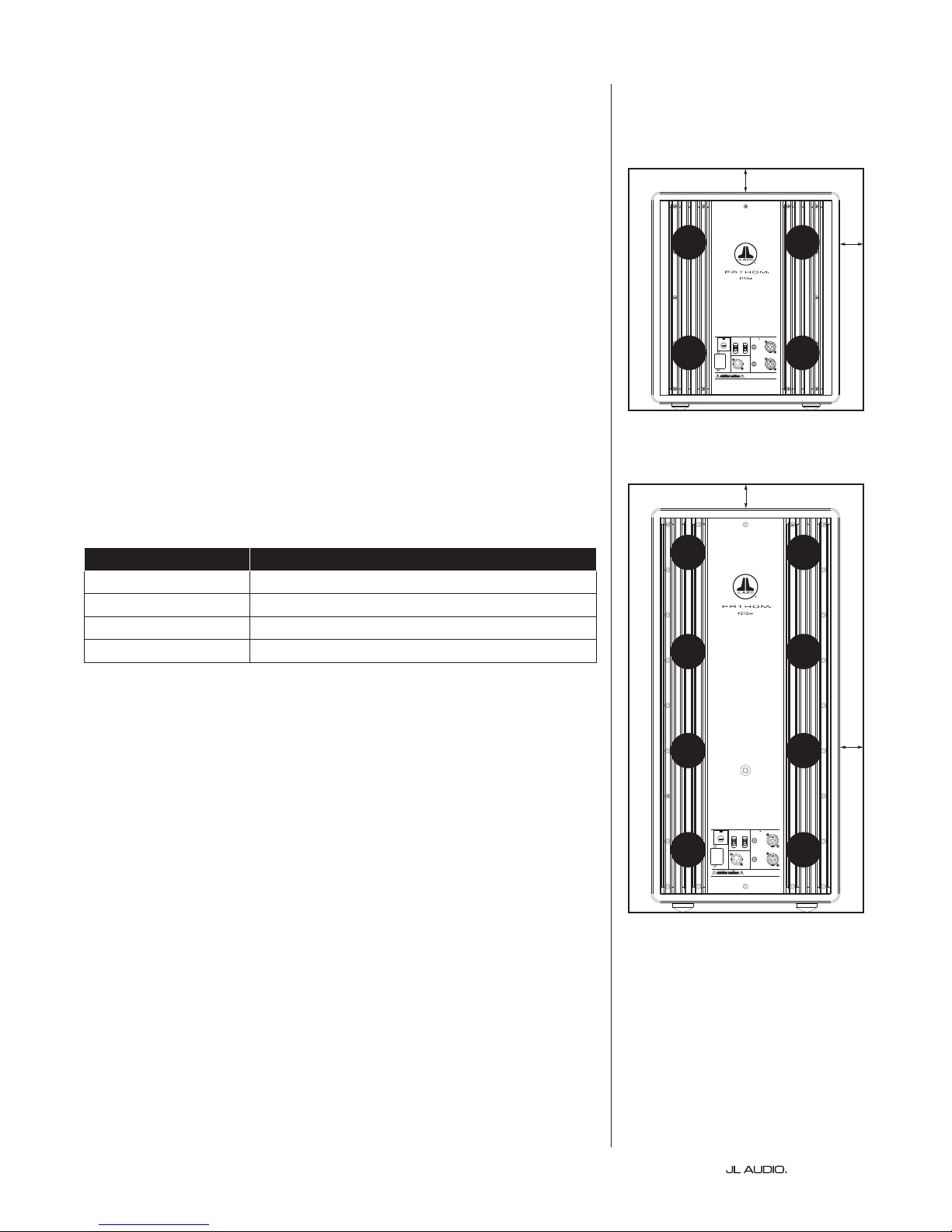
Rear-view of cabinet install (f110, f112, f113):
1) Allow 4 inches (10 cm) of clear space behind the amplier panel for adequate
cooling and connector clearance.
2) On all other sides (except the bottom), allow at least 2 inches
(5 cm) clearance for adequate ventilation.
3) While the Fathom v2 generally runs only warm during spirited operation, we do
recommend that adequate heat vents are included in any custom cabinet which
encloses the Fathom v2. A pair of 3 inch (7.5 cm) diameter vents near the bottom
of the cabinet and near the top of the cabinet, will allow cool air to circulate over
the amp panel of your Fathom v2 subwoofer system keeping it cool and happy.
4) Your Fathom v2 subwoofer is capable of moving substantial quantities of air. If
the front of the Fathom v2 is covered by a custom grille, the grille size must be
AT LEAST equal to the woofer cone area for each model to ensure the output is
not choked by the custom cabinet. Refer to the chart below for recommended
vent areas for each model.
Model Recommended Custom Grille Vent Area
2
f11 0 v2 ≥ 60 in
f112 v2 ≥ 85 in
f113v2 ≥ 108 in
f212 v2 ≥ 170 in
(386 cm2)
2
(550 cm2)
2
(700 cm2)
2
(110 0 c m2)
2 in. min.
VENT
VENT
Built in USA with Imported and domestic components
Input Modes
F 12A H
250V
Grounded
Slave
S
E
U
F
F
U
E
S
120 V ~ 60 Hz
1200VA
Master
Isolated
Output to Slave
(Balanced)
INPUTS
LEFT
or
MONO
Unbalanced
RIGHT
ONLY
SERIAL NUMBER:
Warranty void if serial number is removed, altered or defaced.
VENT
Balanced
VENT
Rear-view of cabinet install (f212):
2 in. min.
VENT
VENT
VENT
VENT
2 in.
min.
VENT
VENT
Built in USA with Imported and domestic components
INPUTS
Input Modes
F 15A H
250V
Grounded
Slave
S
E
U
F
LEFT
F
U
E
S
or
MONO
120 V ~ 60 Hz
Master
Isolated
Unbalanced
Output to Slave
(Balanced)
RIGHT
ONLY
SERIAL NUMBER:
Warranty void if serial number is removed, altered or defaced.
2 in.
min.
VENT
Balanced
VENT
| Fathom v2Page 8
Page 9
Using Two Fathom v2s
When using two Fathom v2s, try
placement near the front corners of the
room, at diagonally-opposite corners
of the room, or at the center points of
opposing walls as shown at right.
Experimentation with
subwoofer and listener
placement is recommended to
achieve the best results – the
benets can be substantial.
High-resolution measurements
and professional system calibration
are recommended for the best possible
results & system performance.
Recommended Subwoofer Placement Options for Two Fathom v2s
ENGLISH
Page 9 | Fathom v2
Page 10
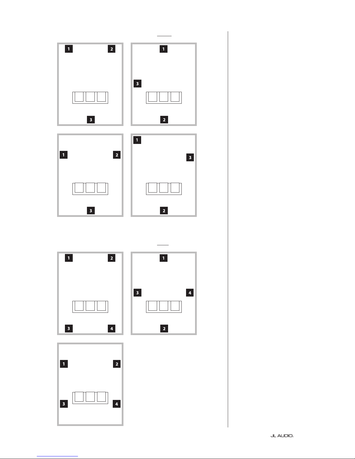
Recommended Subwoofer Placement Options for Three Fathom v2s
Using Three or Four Fathom v2s
Research indicates that the
smoothest bass response for a large
listening area can be achieved using
four subwoofers, placing one at
the midpoint of each of the four
walls (although using two or three
subwoofers can be almost as good).
Experimentation with
subwoofer and listener
placement is recommended to
achieve the best results – the
benets can be substantial.
High-resolution measurements
and professional system calibration
are recommended for the best possible
results & system performance.
Recommended Subwoofer Placement Options for Four Fathom v2s
| Fathom v2Page 10
Page 11
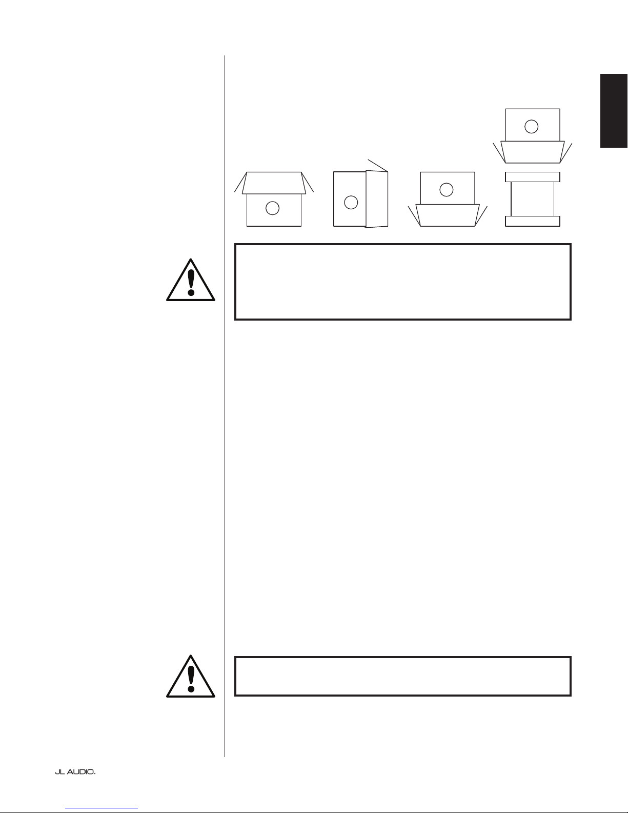
Unpack this box close to where the
subwoofer will be placed. e subwoofer
is PACKED upside down. is box must be
ipped over CAREFULLY to remove the
subwoofer and minimize eort.
IMPORTANT
UNPACKING YOUR FATHOM v2
Now that you have determined your Fathom v2’s position in the room, you can
proceed with unpacking it near its intended location.
D
C
A
IMPORTANT: DUE TO THE WEIGHT OF THE FATHOM V2 SUBWOOFER,
PLEASE EXERCISE CAUTION WHILE UNPACKING AND POSITIONING IT TO
PREVENT INJURY. IF POSSIBLE, ENLIST THE HELP OF A SECOND PERSON TO
FACILITATE THE PROCESS. TO MINIMIZE THE RISK OF INJURY, BEND YOUR
KNEES AND LIFT WITH YOUR LEGS, NOT YOUR BACK.
Detailed instructions on unpacking the subwoofer:
1. Place the carton on the oor near its intended location in the room.
B
ENGLISH
2. Open the top of the carton (observe markings on carton) and remove the manual,
calibration microphone and power cord.
3. Temporarily remove the split-foam packing inserts.
4. Untie and loosen the protective cloth cover to make later removal easier (do
not remove at this time). When you open the cloth cover, you are looking at the
bottom of the subwoofer cabinet.
5. Replace the split-foam inserts to protect the subwoofer’s cabinet
while unpacking.
6. Gently ip the box on its side, folding back the carton aps to the outside.
7. Holding the carton aps back, gently ip the carton onto its top (open end).
8. Pull the carton straight up until it clears the subwoofer and place to one side.
9. Remove the one-piece foam insert and place in the carton.
10. Remove the plastic bag and place in the carton.
11. Tilt the subwoofer forward (toward its grille) to remove the rear split-foam insert
rst. en tilt the subwoofer in the opposite direction (towards its amplier
panel) to remove the remaining split-foam insert. Place both split-foam inserts in
the carton.
12. Remove the protective cloth cover and place in the carton.
IMPORTANT
IMPORTANT! PLEASE RETAIN ALL PACKAGING FOR SAFE TRANSPORTATION
OF THE SUBWOOFER AND FOR ANY FUTURE SERVICE NEEDS.
Page 11 | Fathom v2
Page 12
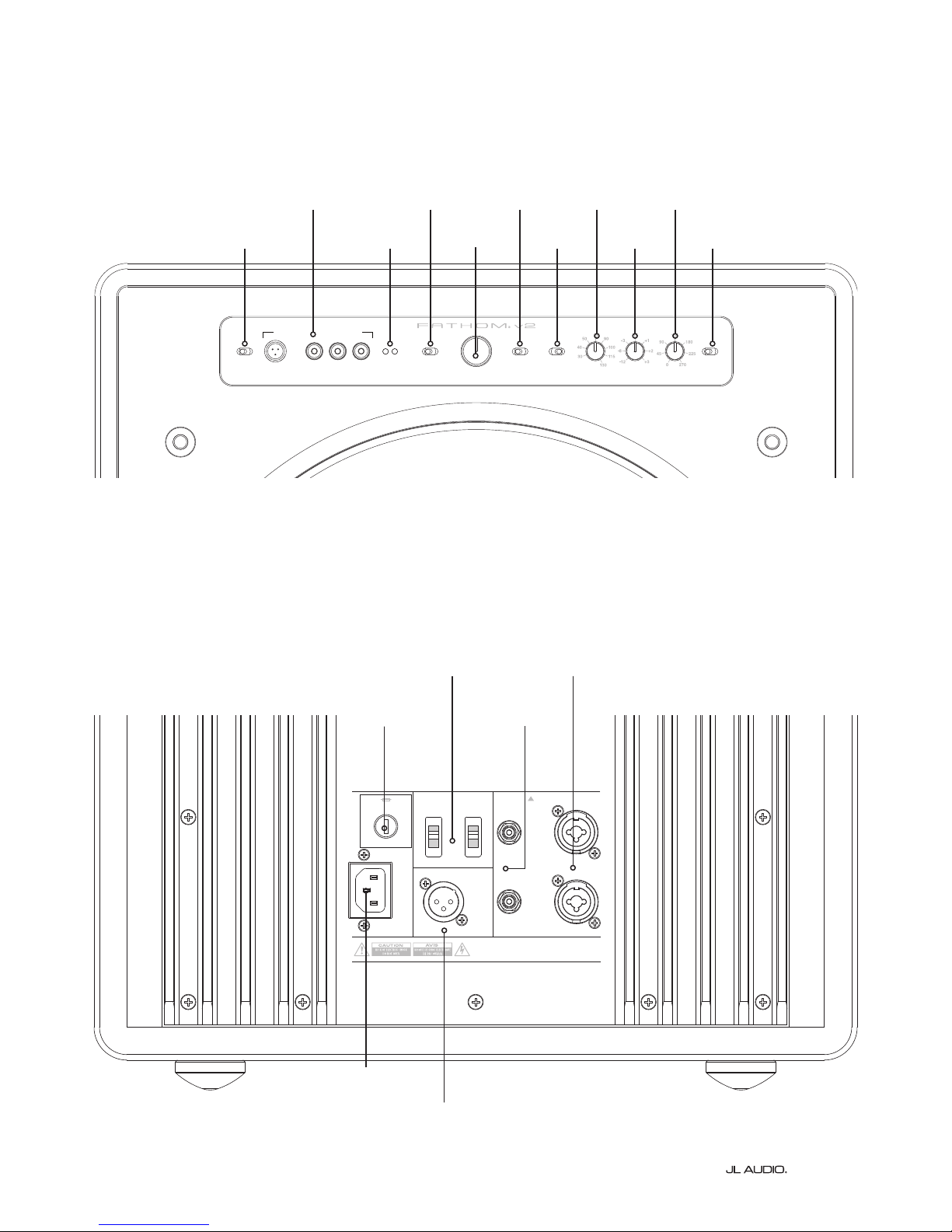
Front Control Panel (All Models)
e labeled Figure below depicts the front control panel of a Fathom f113v2 subwoofer.
e controls layout is the same for all Fathom v2 models.
D.A. R.O.
page 14 -15
Power
page 14
Digital Automatic Room Optimization
Power
o | on | auto
calibration mic. demo defeat calibrate
Level Mod e
Input Mode
page 15
Input Mode
master | slave
page 15
Level Mode
ref. | variable
Master Level
page 16
0
max
-∞
Master Level
Lights
page 16
Lights
o | dim | on
LP freq. (H z)
LP Filter
page 16
LP Filter
o | 12dB | 24dB
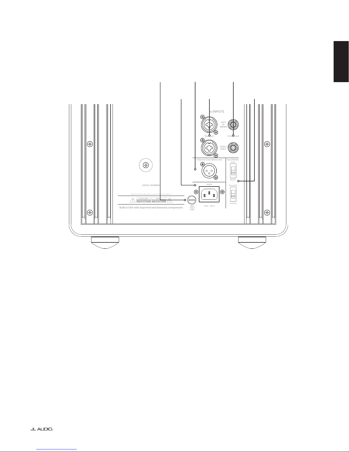
Rear Controls and Connectors (f112v2, f113v2, f212v2 Models)
e labeled Figure below depicts the rear panel of a Fathom f113v2 subwoofer.
e controls and connectors layout is the same for the Fathom f112v2 & f212v2.
page 16
page 17
e.l.f. trim (dB)
page 17
LP freq. (Hz) e.l.f. trim (dB) phase (deg.)
phase (deg.)
Polarity
page 17
Polarity
0 | 180 de g.
Input Mode
Switches
page 20
Region-
Specic Fuse
page 33
Built in USA with Imported and domestic components
F 12A H
250V
E
S
U
F
120 V ~ 60 Hz
1200VA
Input Modes
Slave
F
U
S
E
Master
Output to Slave
Unbalanced
Inputs
page 19
Grounded
Isolated
Unbalanced
(Balanced)
SERIAL NUMBER:
Warranty void if serial num ber is removed, altere d or defaced.
IEC-Style AC
Connector
page 21-22
Output to
Slave Connector
page 21
INPUTS
LEFT
or
MONO
RIGHT
ONLY
Balanced
Inputs
page 18
Balanced
| Fathom v2Page 12
Page 13
Rear Controls and Connectors (f110v2 Model)
e labeled Figure below depicts the rear panel of a Fathom f110v2 subwoofer.
*e rear control and connector detail images throughout this manual depict other Fathom v2 models and are not
representative of the arrangement of the f110v2.
ENGLISH
Region-
Specic Fuse
page 33
Output to
Slave Connector
IEC-Style AC
Connector
page 21-22
page 21
S
E
U
F
F
U
E
S
Balanced
Inputs
page 18
Unbalanced
Inputs
page 19
Input Mode
Switches
page 20
Page 13 | Fathom v2
Page 14
FRONT PANEL CONTROLS IN DETAIL
LP freq. (Hz) e.l.f. trim (dB) phas e (deg.)
Polarity
0 | 180 d eg.
LP Filter
o | 12d B | 24dB
Master Level
max
0
Lights
o | dim | on
-∞
Level Mode
ref. | variable
Input Mode
master | slave
calibration mic. demo defeat calibrate
Power
o | on | auto
Digital Automatic Room Optimization
LP freq. (Hz) e.l.f. trim (dB) phas e (deg.)
Polarity
0 | 180 d eg.
LP Filter
o | 12d B | 24dB
Master Level
max
0
Lights
o | dim | on
-∞
Level Mode
ref. | variable
Input Mode
master | slave
calibration mic. demo defeat calibrate
Digital Automatic Room Optimization
LP freq. (Hz) e.l.f. trim (dB) phas e (deg.)
Polarity
0 | 180 d eg.
LP Filter
o | 12d B | 24dB
Master Level
max
0
Lights
o | dim | on
-∞
Level Mode
ref. | variable
Input Mode
master | slave
calibration mic. demo defeat calibrate
Power
o | on | auto
Digital Automatic Room Optimization
Power Switch
e “Power” switch determines the operational readiness of the Fathom v2
subwoofer and should be the only switch used to turn the Fathom v2 on and o. Do
not use a power strip switch, switched outlet or any other external switch as these
may result in undesirable and potentially damaging transient pops. Do not unplug
the Fathom v2’s AC power cord while the unit is turned on. e power switch has
three positions:
“On”: e Fathom v2 is fully powered at all times. Front panel lights are on
unless they have been turned o via the “Lights” switch.
“O ”: e Fathom v2’s internal power amplier is powered down. In this state,
a negligible current draw will exist for operating the main power relays. All front
panel lights are o .
“Auto”: e Fathom v2 will power up its internal amplier when an audio signal is
present at any of its inputs and will power down the internal amplier if no signal has
been detected at its inputs for thirty (30) minutes. When dormant, the Fathom v2 will
draw a very small amount of current (< 5 watts) to power its signal-sensing circuitry.
Front panel lights will turn o when the Fathom v2 powers down and light when the
Fathom v2 powers up (unless they have been turned o via the “Lights” switch).
In the unlikely event that the Auto feature is not sensitive enough for a particular
system, use a Y-cable adaptor to split the incoming signal into both RCA or XLR
inputs on the Fathom v2. is will increase the input sensitivity by 6 dB. Please be
aware that if the Auto sensitivity is too high or if there is signicant noise on the
input cable, the Fathom v2 may not turn o as desired. If this happens, remove the
Y-cable adaptor or look for the noise source in the upstream components.
IMPORTANT
Digital Automatic Room Optimization (D.A.R.O.)
A powerful feature of the JL Audio Fathom v2 subwoofers is their innovative
Digital Automatic Room Optimization (D.A.R.O.) technology. is one-touch
system includes 18 bands of digital equalization to eliminate the largest acoustic
response peaks in your home theater at the main listening seat, greatly improving
the in-room low-frequency response. Calibration of the D.A.R.O. system is fully
automated. Please consult the next section of this manual for details on how to use
the D.A.R.O. system.
Using the included JL Audio calibration microphone, the D.A.R.O. calibration
procedure takes less than three minutes. In brief, you will connect the included
microphone to the “Calibration Mic.” input, press the Calibrate button, and then
hold the microphone at ear height in your main listening seat during the test. A
noise sequence will be played through the Fathom v2 subwoofer, and the room
response will be automatically measured, analyzed and equalized to eliminate
the single largest acoustic room response peak at your listening seat. For detailed
instructions on the D.A.R.O. setup procedure, refer to pages 29-30.
Calibration Mic. Input
is input is for connecting the supplied JL Audio calibration microphone to the
Fathom v2 subwoofer. Connect one end of the supplied cable to the microphone and
the other end to this jack prior to using the D.A.R.O. system. e D.A.R.O. system
is specically calibrated to this microphone and its connection scheme is specic to
the supplied microphone. e calibration sequence will not operate when a dierent
microphone is connected or if no microphone is connected.
| Fathom v2Page 14
Page 15
LP freq. (Hz) e.l.f. trim (dB) phas e (deg.)
Polarity
0 | 180 d eg.
LP Filter
o | 12d B | 24dB
Master Level
max
0
Lights
o | dim | on
-∞
Level Mode
ref. | variable
Input Mode
master | slave
LP freq. (Hz) e.l.f. trim (dB) phas e (deg.)
Polarity
0 | 180 d eg.
LP Filter
o | 12d B | 24dB
Master Level
max
0
Lights
o | dim | on
-∞
Level Mode
ref. | variable
|
slave
Demo Button
LP freq. (Hz) e.l.f. trim (dB) phas e (deg.)
Polarity
0 | 180 d eg.
LP Filter
o | 12d B | 24dB
Master Level
max
0
Lights
o | dim | on
-∞
Level Mode
ref. | variable
Input Mode
master | slave
Digital Automatic Room Optimization
LP freq. (Hz) e.l.f. trim (dB) phas e (deg.)
Polarity
0 | 180 d eg.
LP Filter
o | 12d B | 24dB
Master Level
max
0
Lights
o | dim | on
-∞
Level Mode
ref. | variable
Input Mode
master | slave
LP freq. (Hz) e.l.f. trim (dB) phas e (deg.)
Polarity
0 | 180 d eg.
LP Filter
o | 12d B | 24dB
Master Level
max
0
Lights
o | dim | on
-∞
Level Mode
ref. | variable
Input Mode
master | slave
e Demo button triggers a 20 second long tone sequence that briey
demonstrates the range of the Fathom v2 subwoofer. e Demo function is useful
for showcasing the output capability of the Fathom v2 and to verify that the Fathom
v2 (or multiple Fathom v2s) are operational during system troubleshooting.
e Demo button is also used (in combination) to clear (return to at) the
D.A.R.O. equalizer settings. To clear the D.A.R.O.’s settings & turn o the Calibrate
light, press and hold the Demo button and then press the Defeat button. Please note
that you must perform this button sequence quickly. If you hold the Demo button
for more than 2 seconds without touching the Defeat button, the Demo tones will
start. Should this happen, simply wait for the Demo sequence to end and try again.
Defeat Button
If “Demo” or “Calibrate” is pressed while the defeat function is active, “Defeat” is
automatically canceled. No other front panel controls will alter the D.A.R.O. Defeat
state. e Defeat setting is stored in non-volatile memory and will not change even if
power is disconnected.
e Defeat button is also used (in combination) to clear (return to at) the
D.A.R.O. equalizer settings. To clear the D.A.R.O.’s settings & turn o the Calibrate
light, press and hold the Demo button and then press the Defeat button. Please note
that you must perform this button sequence quickly. If you hold the Demo button
for more than 2 seconds without touching the Defeat button, the Demo tones will
start. Should this happen, simply wait for the Demo sequence to end and try again.
ENGLISH
Calibrate Button
During the D.A.R.O. test sequence, the Calibrate button’s green LED will blink
quickly to alert the user to two special conditions:
1. “JL Audio Microphone NOT Connected”: If you forget to connect the mic
before trying to start a Calibration you will get this alert. Press the Calibrate button
once to cancel the alert, connect the D.A.R.O. microphone, and try again.
2. “Inappropriate Sound Level for D.A.R.O. Calibration”: Since the D.A.R.O.
sequence is completely automatic, this alert likely indicates a problem with the
microphone. Press the Calibrate button once to cancel the alert. Ensure that the JL
Audio microphone is properly connected and try again. For further help, please refer
to Troubleshooting on page 33.
Input Mode Indicators
e Input Mode indicator LEDs show the input mode, either “Master” or “Slave”,
selected by the switch on the Fathom v2’s back panel (unless the “Lights” switch is
set to “o”). For further details, see page 20.
Level Mode
e two-position Level Mode switch allows you to select between
the following modes:
“Reference”: In this mode, the Master Level control knob has no eect on the
Fathom v2’s output level. Use this setting if you will primarily be controlling the
subwoofer level via your receiver or preamplier/processor. For those of us with
small children or overenthusiastic teenagers, this mode of operation will prevent
direct manipulation of the Master Level.
“Variable”: In this mode, the Master Level control knob determines the output
level of the Fathom v2 subwoofer. is mode is also useful when level matching the
Fathom v2 subwoofer to a pair of stereo speakers in a two-channel system.
Page 15 | Fathom v2
Page 16
Master Level Knob
LP freq. (Hz) e.l.f. trim (dB) phas e (deg.)
Polarity
0 | 180 d eg.
LP Filter
o | 12d B | 24dB
Master Level
max
0
Lights
o | dim | on
-∞
LP freq. (Hz) e.l.f. trim (dB) phas e (deg.)
Polarity
0 | 180 d eg.
LP Filter
o | 12d B | 24dB
max
Lights
o | dim | on
LP freq. (Hz) e.l.f. trim (dB) phas e (deg.)
Polarity
0 | 180 d eg.
LP Filter
o | 12d B | 24dB
|
on
LP freq. (Hz) e.l.f. trim (dB) phas e (deg.)
Polarity
0 | 180 d eg.
|
24dB
e Master Level Knob is used to control the output level of the Fathom v2
when the Variable Level mode is selected on the front control panel.
When rotated fully counter-clockwise, the Fathom v2’s output will be fully
muted. When at the “0” or vertical position, the Variable gain level matches the
Reference level setting. When turned fully clockwise, the Fathom v2’s output level
is 15 dB higher than the Reference setting.
Lights
e “Lights” selector switch allows the user to select one of three indicator
light modes.
“O” turns o all of the front panel LED’s at all times.
“Dim” sets all of the front panel LEDs to a low brightness level when the
Fathom v2 is turned on.
“On” sets all of the front panel LEDs to full brightness level when the Fathom
v2 is turned on.
IMPORTANT: WHEN TROUBLESHOOTING OR CALIBRATING THE D.A.R.O.
FEATURE, MAKE SURE THAT THE “LIGHTS” SWITCH IS SET TO “DIM” or “ON.”
LP Filter
e Low Pass (LP) Filter selector switch determines the operating mode of the
Fathom v2’s built-in low pass lter.
“O” defeats the low pass lter, completely removing this circuit from the
signal path.
“12 dB” sets the roll o slope of the low pass lter to a 12 dB per octave slope
(Butterworth alignment).
“24 dB” sets the roll o slope of the low pass lter to a 24 dB per octave slope
(Linkwitz-Riley alignment).
e 24 dB setting more aggressively attenuates high frequencies above the LP
Frequency setting (see below). If you are using the Fathom v2’s built-in low pass
lter, experiment with the LP Filter slope setting to achieve the best transition
to your satellite speakers. If you prefer to use the lters and bass management
features in your receiver or preamplier, defeat the on-board lter by selecting
the “O” position.
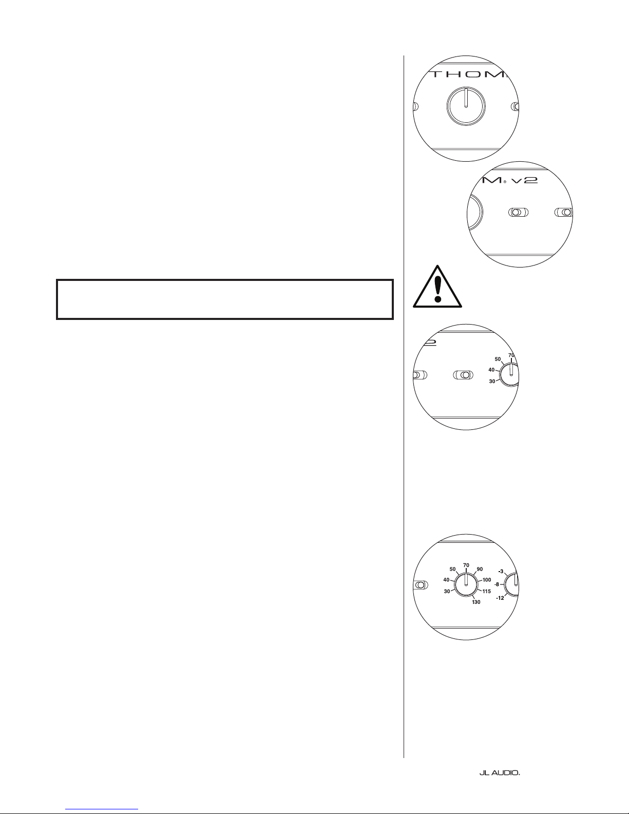
LP Freq
e Low Pass (LP) Frequency selector knob allows the user to choose the rollo frequency of the Fathom v2’s internal low pass lter. e frequency is variable
between 30 Hz (full counter-clockwise) to 130 Hz (full clockwise). is knob does
not aect the input signal in any way if the LP Filter switch is set to “O ”. 80 Hz
is a commonly used lter frequency and usually serves as a good starting point
for adjustments.
IMPORTANT
| Fathom v2Page 16
Page 17
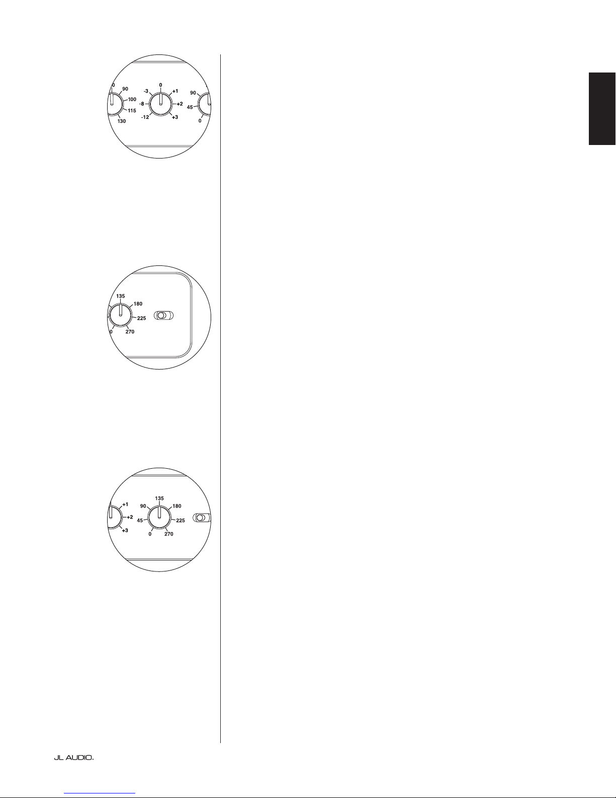
E.L.F. Trim
Polarity
0 | 180 d eg.
Polarity
0 | 180 d eg.
Polarity
0 | 180 d eg.
e Extreme Low Frequency (“e.l.f. trim”) knob allows the user to apply
a certain amount of signal equalization at 24 Hertz (extremely low bass). At
full counter-clockwise rotation, the signal at 24 Hz is cut by 12 dB. At “0” the
equalizer is set at for zero contribution to the signal. At full clockwise rotation,
the signal at 24 Hz is boosted by 3 dB.
e e.l.f. trim feature is useful for tailoring the Fathom v2’s very low frequency
output for your particular room. Adding some boost can make certain material
feel more exciting. Using the cut function can help to compensate for room or
boundary gain in the low frequencies. Room boundaries and the room’s nite
(limited) size naturally cause very low frequencies to be boosted relative to
other parts of the signal. As such, using the e.l.f. trim feature to cut the lowest
frequencies can help to tame “bloat” or unnatural sounding low bass in small to
medium sized rooms (and can also reduce unwanted vibrations in the room or
throughout the house).
Polarity
e Polarity switch allows the user to select between normal (0 deg) and
reversed (180 deg) signal polarity. e Polarity switch will primarily aect the
small frequency range around the crossover point between your subwoofer and
satellite speakers.
Unlike the Phase control, which eectively adds time delay, the Polarity
switch produces an instantaneous reversal of the signal’s amplitude peaks.
For example, if at a given reference point a sine wave has an amplitude peak,
by ipping the phase switch you instantly convert that peak into a trough
or amplitude dip. Because the eect of the Polarity switch is immediate, it
compliments the operation of the Phase control and cannot be replaced by it.
When placing your Fathom v2 in the room, experiment with the Polarity switch
before adjusting the “Phase” control. Either position of the Polarity switch may
provide a smoother transition between your Fathom v2 subwoofer and the satellite
speakers. Use source material with good mid and upper bass content for evaluation.
ENGLISH
Phase
e Phase control knob allows the user to adjust the “timing” of the
subwoofer output relative to the main speakers. e Phase control will primarily
aect the small frequency range around the crossover point between your
subwoofer and satellite speakers. Phase settings between 0 degrees (full counterclockwise rotation) and 270 degrees (full clockwise rotation) are possible. e
Phase control’s labels are referenced to a frequency of 80 Hz since this is the most
common crossover point between satellite speakers and a subwoofer.
Speaker, subwoofer, and listening seat positions vary greatly in home
theater installations. Since physical positioning of speakers relative to the room
boundaries, and each other, greatly aects the perceived quality of sound output,
sometimes it is helpful to delay the subwoofer output. is is exactly what occurs
when you turn the Phase control beyond 0 degrees.
Once your Fathom v2 has been placed in your listening room to give you the
smoothest overall sound and aer you have determined the optimum “Polarity”
switch position (see preceding section), experiment with the position of the Phase
control. Using familiar source material with good mid and upper bass content,
adjust the Phase control and listen for better dened mid-bass and a smoother
transition between the subwoofer and satellite speaker systems. If no single
setting sounds better than another, leave the Phase control at 0 degrees.
Page 17 | Fathom v2
Page 18
CONNECTING YOUR FATHOM v2
LEFT
or
MONO
RIGHT
ONLY
INPUTS
Balanced
Unbalanced
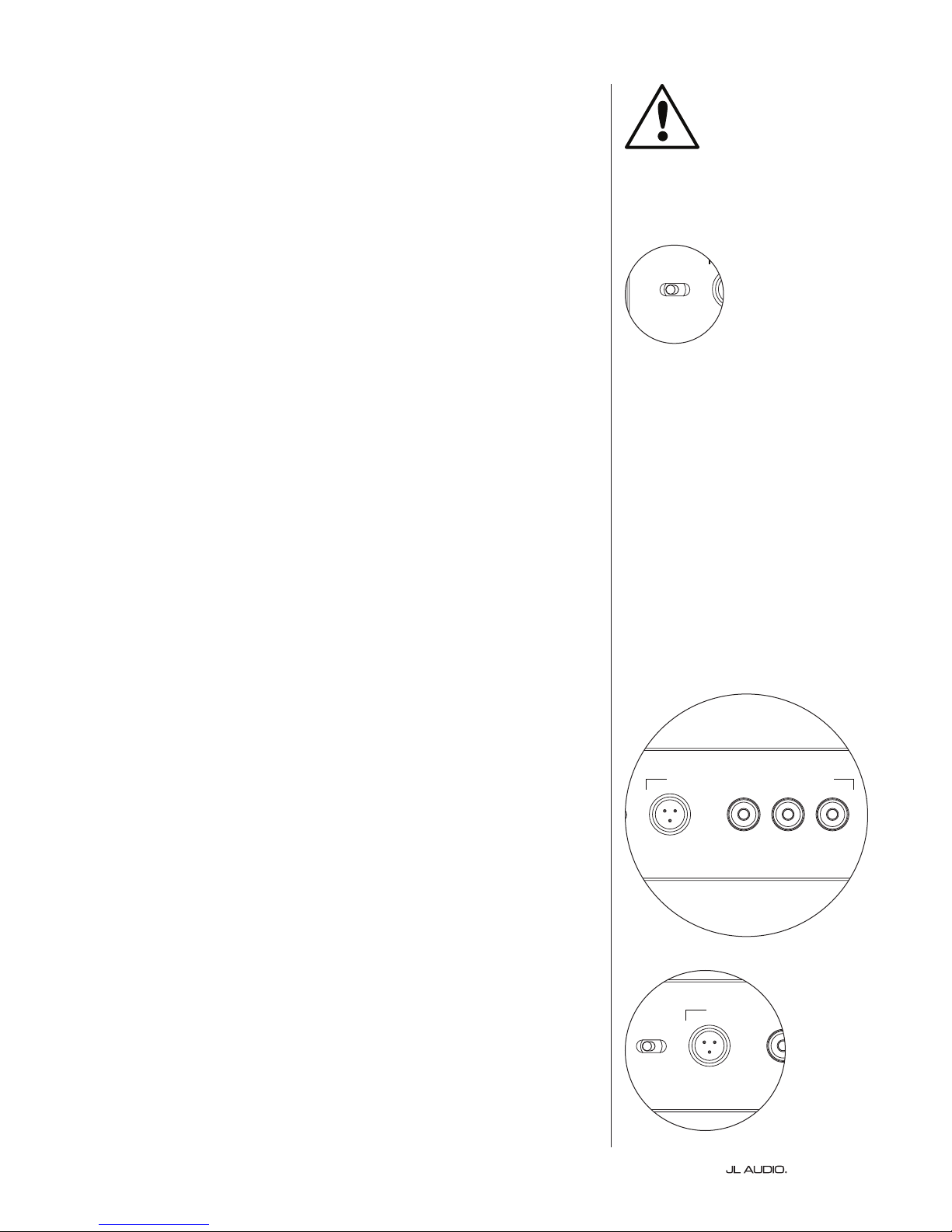
Balanced Inputs
If your home-theater receiver or preamplier/processor provides balanced
outputs, the Fathom v2’s balanced inputs are the preferred connection. Balanced
connections are used extensively in professional studios and sound reinforcement
applications for a number of very good reasons. Besides ensuring proper grounding
between components, balanced signal transmission is designed to cancel induced
cable noise from the surrounding environment (particularly important with long
cable runs). e bottom line is that your system will be far less likely to exhibit
humming or other extraneous noises if you use balanced connections.
e Fathom v2 subwoofers feature individual le and right balanced input
connections with XLR “combo” jacks. ese special jacks accept either a
three-pin male XLR connector or a “tip-ring-sleeve” (TRS) 1/4-inch (6.3 mm)
connector for compatibility with a wide range of equipment.
For systems with a mono subwoofer or “LFE” channel connection, only the
jack labeled “Le or Mono” will be used. is applies to most modern multichannel receivers and preamplier/processors. Separate le and right input jacks
are provided for systems without a dedicated mono subwoofer connection. is
typically applies to two-channel audio equipment.
Appropriate balanced cables are available from your JL Audio dealer and are
not included with the Fathom v2.
Technical Notes:
• Do not use the balanced inputs with unbalanced signals via adaptors. e
unbalanced inputs of the Fathom v2 are optically isolated and preferable in
situations where only an unbalanced signal source is available. Balanced input
impedance is 10 kohms.
• Input connectors are congured according to Audio Engineering Society
recommendations for balanced signal cables as follows:
XLR Connection
Pin 1: Shield
Pin 2: Positive
Pin 3: Negative
TRS connection:
Tip: Positive
Ring: Negative
Sleeve: Shield
e Le and Right inputs on the Fathom
v2 are internally summed to a single mono
channel. Since the Fathom v2 is inherently
a “mono” or single channel device, you can
use the Le and Right inputs for the master
Fathom v2 and then distribute the summed
mono signal to additional slave Fathom v2s
in the system.
IMPORTANT: IF YOUR RECEIVER OR PREAMPLIFIER/PROCESSOR DOES NOT
HAVE XLR OR 1/4-INCH TRS BALANCED OUTPUTS, PLEASE REFER TO THE
“UNBALANCED INPUTS” SECTION ON PAGE 19 FOR INPUT CONNECTION
INFORMATION. DO NOT ATTEMPT TO CONNECT UNBALANCED OUTPUTS
TO THE FATHOM V2’S BALANCED INPUTS VIA ADAPTORS.
IMPORTANT
| Fathom v2Page 18
Page 19

Unbalanced Inputs
LEFT
or
MONO
RIGHT
ONLY
INPUTS
Output to Slave
(Balanced)
Balanced
Unbalanced
Input Modes
Grounded
Isolated
e Fathom v2 subwoofer features individual le and right unbalanced RCAtype input connectors. ese are the most commonly used connectors for home
audio applications and must be used if your receiver or preamplier/processor
does not provide balanced outputs. While unbalanced connections are not as
noise-immune as a balanced connection, Fathom v2 subwoofers employ optical
isolation on the unbalanced inputs to minimize the possibility of noise in your
system.
For systems with a mono subwoofer or “LFE” channel connection, only
the RCA-type jack labeled “Le or Mono” will be used. is applies to most
modern multi-channel receivers and preamplier / processors. Separate le and
right RCA-type input jacks are provided for systems without a dedicated mono
subwoofer connection. is typically applies to two-channel audio equipment.
Technical Notes:
• When balanced outputs are not available on the signal source, you must
use the RCA-type unbalanced inputs. Fathom v2s feature optical isolation
circuitry on the unbalanced inputs to minimize the likelihood of ground
loop induced noise. Unbalanced input impedance is 50 kohms.
• Connections are industry-standard for unbalanced signal cables as follows:
RCA-type connection:
Tip: Positive
Sleeve: Negative
ENGLISH
IMPORTANT
IMPORTANT: IF NOISE EXISTS AFTER CONNECTION, FATHOM V2s ALLOW
FOR GROUNDING OR ISOLATION OF THE UNBALANCED INPUTS. PLEASE
REFER TO THE “INPUT MODE SWITCHES” SECTION ON PAGE 20 OF THIS
MANUAL FOR FURTHER INFORMATION ON MINIMIZING NOISE.
Page 19 | Fathom v2
Page 20
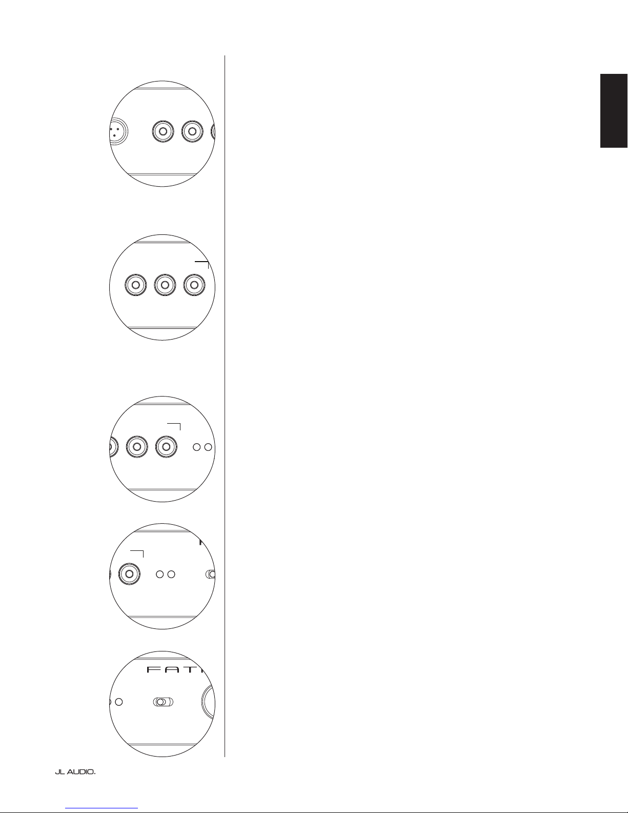
Input Mode Switches:
LEFT
or
MONO
RIGHT
ONLY
INPUTS
Output to Slave
(Balanced)
Balanced
Unbalanced
Input Modes
Slave
Master
Grounded
Isolated
U
S
E
1200 VA
Built in USA with Imported and domestic components
LEFT
or
MONO
RIGHT
ONLY
INPUTS
Output to Slave
(Balanced)
Balanced
Unbalanced
Input Modes
Slave
Master
Grounded
Isolated
F 12A H
250V
120 V ~ 60 Hz
F
U
S
E
F
U
S
E
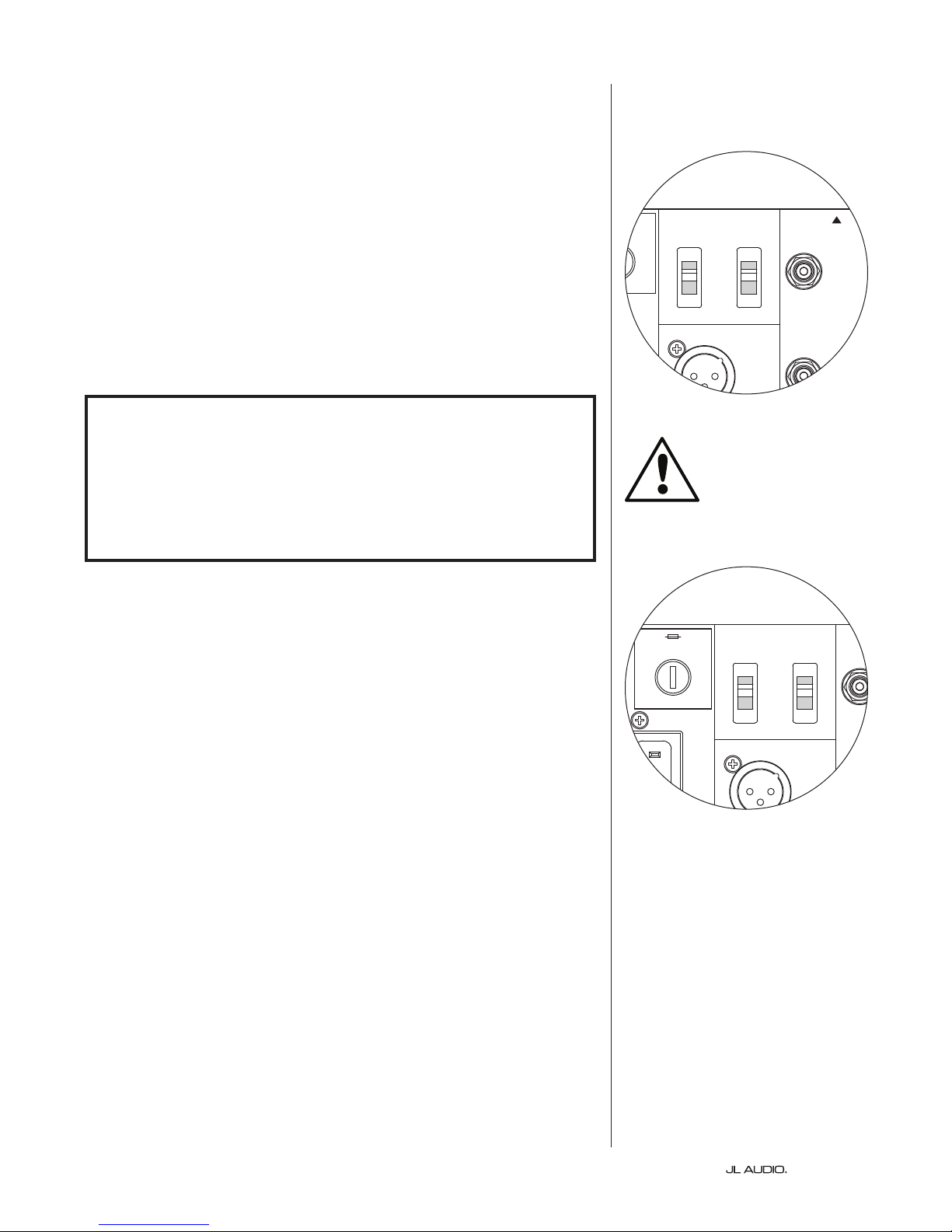
Two switches are located on the rear panel to control unbalanced signal
grounding and master/slave operation.
“Grounded / Isolated” Switch
e “Grounded / Isolated” Input Mode switch aects only the unbalanced
RCA inputs and is designed to facilitate a quiet, hum-free connection to your
audio or home theater system. is feature is included to deal with the signal
grounding issues oen encountered in home theater systems when several
components from dierent manufacturers are interconnected.
e Fathom v2 ships with this switch in the “Isolated” mode. If, with all system
components connected and turned on (but no source material playing), you hear
a continuous low-frequency hum through your Fathom v2, ip this switch to the
“Grounded” position and evaluate the dierence in the noise level. Use whichever
switch position provides the least hum or noise.
IMPORTANT: PLEASE NOTE THAT CHANGING ANY COMPONENT IN
THE OPTIMIZED SYSTEM (RECEIVER, AMPLIFIER, DVD PLAYER, CABLE OR
SATELLITE BOX, ETC.) COULD ALTER THE SIGNAL GROUNDING SCHEME
AND CAUSE HUM TO APPEAR IN YOUR PREVIOUSLY QUIET SYSTEM. IF YOU
ADD OR CHANGE AN UPSTREAM COMPONENT IN YOUR HOME THEATER
SYSTEM, YOU MAY NEED TO REVISIT THIS INPUT MODE SETTING ON THE
FATHOM V2 SUBWOOFER FOR OPTIMUM NOISE PERFORMANCE. CABLE &
SATELLITE BOXES ARE PARTICULARLY TROUBLESOME IN THIS WAY.
IMPORTANT
Master / Slave Switch
e Fathom v2s are designed to easily accommodate the implementation
of multiple subwoofers in your home theater system through a master/slave
connection chain. is method allows you to utilize the signal processing
features of one Fathom v2 to centrally control multiple Fathom v2s in the room.
Master/Slave functionality also makes it possible for the D.A.R.O. system to
optimize the response of a multiple subwoofer installation.
e Fathom v2 ships with this switch in the “Master” position. If you are using
a single Fathom v2 you will use the “Master” position and you need not concern
yourself with this section any further.
If your installation incorporates two or more Fathom v2s, you will designate
one Fathom v2 as the “Master” and all others in the system as “Slave” subwoofers
via the “Master/Slave” switch on the rear amplier panel of each Fathom v2.
LED’s on the front panel of the Fathom v2 are provided to indicate whether the
“Master” or “Slave” mode is selected for a given subwoofer.
From the Fathom v2 operating in “Master” mode, the “Output to Slave” signal
carries any signal processing selected on the Master Fathom v2 (including the
Master Level setting and D.A.R.O. processing) to further Fathom v2s operating
in “Slave” mode. “Slave” subwoofer signal processing and level controls will be
inoperable. In this mode, the user does not have to worry about level, crossover,
and other settings for the slave subwoofers.
Technical Notes:
• Selecting the “Slave” position defeats all user-denable signal processing and
the master level control. Because of this, there are some special situations
in which you may want to operate a single Fathom v2 in “Slave” mode. If
you are utilizing outboard signal processing and level-matching controls,
activating the “Slave” mode will prevent anyone from aecting system
parameters with the manual controls on the Fathom v2.
| Fathom v2Page 20
Page 21
IMPORTANT
1200 VA
Built in USA with Imported and domestic components
LEFT
or
MONO
RIGHT
ONLY
INPUTS
Output to Slave
(Balanced)
Balanced
Unbalanced
Input Modes
Slave
Master
Grounded
Isolated
SERIAL NUMBER:
Warranty void if se rial number is remove d, altered or deface d.
F 12A H
250V
120 V ~ 60 Hz
F
U
S
E
F
U
S
E
IMPORTANT: PLEASE REFER TO THE “SYSTEM CONNECTION DIAGRAMS”
ON PAGES 22-25 FOR MORE INFORMATION ON USING THE INPUT /
OUTPUT CONNECTIONS.
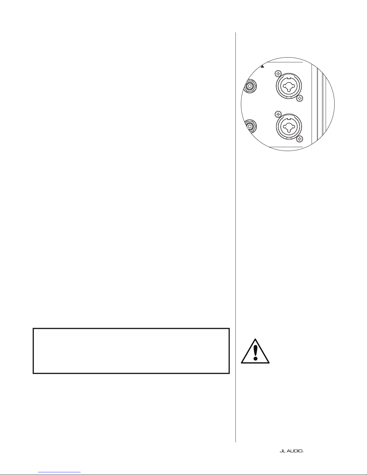
“Output to Slave” Connector
If you are operating more than one Fathom v2 subwoofer in one home theater
system, you will designate one Fathom v2 as the Master (see page 20), and then
feed signal from it to the remaining “Slave” Fathom v2s via this balanced XLR
output. e “Output to Slave” cable can be connected to the “Le or Mono”
balanced XLR input on the next Fathom v2. When a Fathom v2 is in “Slave”
Mode, its “Output to Slave” connection can be used to pass signal to further
Fathom v2s operating in “Slave” mode.
e “Output to Slave” connector is designed to be used as follows:
1) From the “Master” Fathom v2’s “Output to Slave” connector to the rst
“Slave” Fathom v2’s “Le or Mono” XLR balanced input.
2) From the rst “Slave” Fathom v2’s “Output to Slave” connector to the
second “Slave” Fathom v2’s “Le or Mono” XLR balanced input.
3) From the second “Slave” Fathom v2’s “Output to Slave” connector to the
third “Slave” Fathom v2’s “Le or Mono” XLR balanced input. Etc, etc. (up
to ten Fathom v2s may be connected in this conguration). Appropriate
balanced cables with XLR terminations are available from your JL Audio
dealer and are not included with the Fathom v2.
Technical Notes:
• e “Output to Slave” signal carries any signal processing selected on
the Master Fathom v2 (including the Master Level setting and D.A.R.O.
processing) to further Fathom v2s operating in “Slave” mode.
• From Fathom v2s operating in “Slave” mode, the “Output to Slave” signal is
an exact, buered replica of the balanced input signal, making this method
of signal distribution preferable to using Y-adapters or splitters.
• Use only shielded, connection cables with high quality XLR connectors for
Master/Slave connection. Never use unbalanced cables with adaptors.
ENGLISH
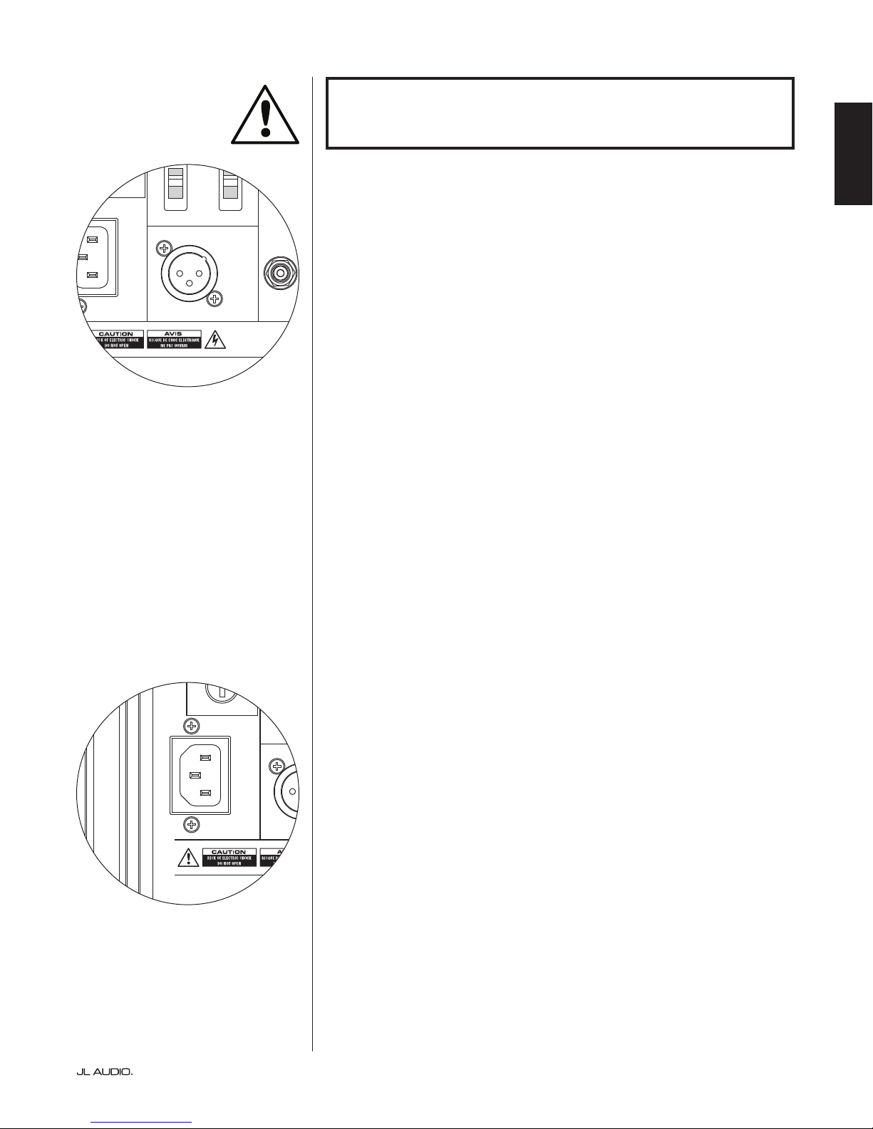
IEC-Style AC Power Connector
e IEC-style AC cord receptacle receives the heavy-gauge, 6 . (1.8 m) long,
power cord included with your Fathom v2 subwoofer. Fathom v2s sold in dierent
parts of the world are congured for each market’s electrical system and include
appropriate plugs on their power cords. Please note the voltage markings next to
the AC connector and make sure you are only powering your Fathom v2 from
a receptacle that matches these markings. Do not use any AC power cord other
than the one supplied with the Fathom v2. For information about the Main Fuse
Holder, please see the Troubleshooting section of this manual.
e Fathom v2 subwoofer is a very powerful device and can draw a lot of
current. If too many components are connected with a Fathom v2 subwoofer
to one electrical outlet, you risk tripping a household circuit breaker during
very demanding program material. If this happens, split the Fathom v2 and
other components between two AC electrical circuits. If possible, for maximum
performance, dedicate an AC circuit to each Fathom v2.
Page 21 | Fathom v2
Page 22

1200VA
LEFT
or
MONO
RIGHT
ONLY
INPUTS
Output to Slave
(Balanced)
Balanced
Unbalanced
Input Modes
Slave
Master
Grounded
Isolated
SERIAL NUMBER:
Warranty void if serial number is removed, altered or defaced.
F 12A H
250V
F
U
S
E
F
U
S
E
FRONT
PROCESSOR (BALANCED OUTPUTS)
RECEIVER / PROCESSOR (UNBALANCED OUTPUTS)
FRONT
PRE OUT
REAR CENTER
L
REAR
R
OR
SUB
Slave
Master
FATHOM REAR CONTROLS (MASTER)
OUTPUTS
SYSTEM CONNECTION DIAGRAM 1:
One Fathom v2 to
Home Theater Receiver or
Home Theater Preamp/Processor
Most home theater receivers and
preamp/processors provide a single
(mono) subwoofer output. When
connecting a mono subwoofer output
to your Fathom v2, you will only use the
Fathom’s “Le or Mono” input.
Two connection types are available
for connecting the Fathom v2 to your
home theater system: balanced (XLR or
1/4-inch TRS connector) and unbalanced
(RCA-type connector). Balanced
connections provide superior noise
rejection and ensure proper grounding
between components. If your receiver or
processor has balanced outputs, we highly
recommend that you use them.
In the connection diagram at le,
balanced connections are shown as solid
lines, unbalanced connections are shown
dotted. You will only use one of these
input connection methods (not both).
WARNING! TURN OFF THE FATHOM v2 AND ALL OTHER EQUIPMENT IN
THE SYSTEM BEFORE MAKING OR CHANGING ANY CONNECTIONS!
WARNING
| Fathom v2Page 22
Page 23

SYSTEM CONNECTION DIAGRAM 2:
1200VA
LEFT
or
MONO
RIGHT
ONLY
INPUTS
Output to Slave
(Balanced)
Balanced
Unbalanced
Input Modes
Slave
Master
Grounded
Isolated
SERIAL NUMBER:
Warranty void if serial number is removed, altered or defaced.
F 12A H
250V
F
U
S
E
F
U
S
E
1200VA
LEFT
or
MONO
RIGHT
ONLY
INPUTS
Output to Slave
(Balanced)
Balanced
Unbalanced
Input Modes
Slave
Master
Grounded
Isolated
SERIAL NUMBER:
Warranty void if serial number is removed, altered or defaced.
F 12A H
250V
F
U
S
E
F
U
S
E
PROCESSOR (BALANCED OUTPUTS)
RECEIVER / PROCESSOR (UNBALANCED OUTPUTS)
Multiple Fathom v2s to
Home Theater Receiver or
Home Theater Preamp/Processor
To greatly simplify using multiple
subwoofers in a single home theater
system, Fathom v2s incorporate a
“Master/Slave” signal distribution system.
is allows control of all the Fathom v2s
in a system from a single “Master” unit.
First, you will select a Fathom v2
subwoofer as the “Master” via its upper
“Input Mode” switch. Generally, you will
designate the Fathom v2 closest to the
receiver/preamp as the master. In some
cases; for example, when the control panel
of certain units is dicult to access, you
may prefer to designate the one which is
easiest to access as the master.
Two connection types are available for
connecting the master Fathom v2 to your
home theater system: balanced (XLR or
1/4-inch TRS connector) and unbalanced
(RCA-type connector). Balanced
connections provide superior noise
rejection and ensure proper grounding
between components. If your receiver or
processor has balanced outputs, we highly
recommend that you use them to connect
to the Fathom v2 designated as the master.
In the connection diagram at le,
balanced connections are shown as solid
lines, unbalanced connections are shown
dotted. You will only use one of these
input connection methods for the Fathom
v2 designated as the master (not both).
e remaining Fathom v2s in the
system will be congured as “Slave” units
via their upper “Input Mode” switches.
Using balanced XLR cables, you will
connect the master Fathom v2’s “Output
to Slave” to the “Le or Mono” balanced
input of the rst slave Fathom v2. at
slave unit’s “Output to Slave” connector
will feed the “Le or Mono” input of
the next slave unit via another balanced
XLR cable. Subsequent slave units will
be connected in the same manner.
FRONT
FRONT
PRE OUT
REAR CENTER
L
REAR
R
OR
SUB
ave
Master
FATHOM REAR CONTROLS (MASTER)
ave
Master
FATHOM REAR CONTROLS (SLAVE)
OUTPUTS
TO ADDITIONAL FATHOMS
(IF APPLICABLE)
ENGLISH
IMPORTANT
Connections between the “Master” and
“Slave” Fathoms and between “Slave”
Fathoms are via balanced XLR cables ONLY.
WARNING
WARNING! TURN OFF THE FATHOM V2(s) AND ALL OTHER EQUIPMENT IN
THE SYSTEM BEFORE MAKING OR CHANGING ANY CONNECTIONS!
Page 23 | Fathom v2
Page 24

1200VA
LEFT
or
MONO
RIGHT
ONLY
INPUTS
Output to Slave
(Balanced)
Balanced
Unbalanced
Input Modes
Slave
Master
Grounded
Isolated
SERIAL NUMBER:
Warranty void if serial number is removed, altered or defaced.
F 12A H
250V
F
U
S
E
F
U
S
E
STEREO ACTIVE CROSSOVER (BALANCED OUTPUTS)
STEREO ACTIVE CROSSOVER (UNBALANCED OUTPUTS)
LOW OUT
(SUB OUT)
RIGHTLEFT
Slave
aster
FATHOM REAR CONTROLS (MASTER)
OR
LOW OUT
(SUB OUT)
SYSTEM CONNECTION DIAGRAM 3:
One Fathom v2 in Mono to
Two-Channel Audio System
When connecting a Fathom v2 (or
multiple Fathom v2s) in mono to a twochannel audio system you will use both
the “Le or Mono” and the “Right” inputs.
Summing circuitry in the Fathom v2’s
input section will sum the stereo signals
to mono.
We strongly recommend that you use
a high-quality active crossover, like the
JL Audio CR-1, to divide your
preamplier’s signals prior to connection
to the Fathom v2 and to the amplier
driving your main speakers. is will
allow you to lter low frequencies out of
the signals driving the main speakers,
resulting in better performance.
If you are not using an active crossover
and are comfortable running your main
speakers full-range, you can split your
preamplier’s output signals using
appropriate Y-connectors in place of the
active crossover shown in the diagram.
Two connection types are available
for connecting the Fathom v2 to your
two-channel audio system: balanced
(XLR or 1/4-inch TRS connector) and
unbalanced (RCA-type connector).
Balanced connections provide superior
noise rejection and ensure proper
grounding between components. If your
preamplier or active crossover oers
balanced outputs, we highly recommend
that you use them.
In the connection diagram at le,
balanced connections are shown as solid
lines, unbalanced connections are shown
dotted. You will only use one of these
input connection methods (not both).
NOTE: If desired, additional Fathom v2s
can be connected in “Slave” mode to the
Fathom v2 connected as shown on this
diagram. See “Connection Diagram 2” on
page 23 for slave connection explanation.
WARNING! TURN OFF THE FATHOM V2 AND ALL OTHER EQUIPMENT IN
THE SYSTEM BEFORE MAKING OR CHANGING ANY CONNECTIONS!
WARNING
| Fathom v2Page 24
Page 25

SYSTEM CONNECTION DIAGRAM 4:
1200VA
LEFT
or
MONO
RIGHT
ONLY
INPUTS
Output to Slave
(Balanced)
Balanced
Unbalanced
Input Modes
Slave
Master
Grounded
Isolated
SERIAL NUMBER:
Warranty void if serial number is removed, altered or defaced.
F 12A H
250V
F
U
S
E
F
U
S
E
1200VA
LEFT
or
MONO
RIGHT
ONLY
INPUTS
Output to Slave
(Balanced)
Balanced
Unbalanced
Input Modes
Slave
Master
Grounded
Isolated
SERIAL NUMBER:
Warranty void if serial number is removed, altered or defaced.
F 12A H
250V
F
U
S
E
F
U
S
E
PROCESSOR (BALANCED OUTPUTS)
RECEIVER / PROCESSOR (UNBALANCED OUTPUTS)
Two Fathom v2s in Stereo to
Two-Channel Audio System
When connecting two Fathom v2s in
stereo to a two-channel audio system you
will only use the “Le or Mono” inputs of
each Fathom v2. e upper “Input Mode”
switch on each Fathom v2 will be set in
the “Master” position.
We strongly recommend that you use
a high-quality active crossover, like the
JL Audio CR-1, to divide your
preamplier’s signals prior to connection
to the Fathom v2 and to the amplier
driving your main speakers. is will
allow you to lter low frequencies out of
the signals driving the main speakers,
resulting in better performance.
If you are not using an active crossover
and are comfortable running your main
speakers full-range, you can split your
preamplier’s output signals using
appropriate Y-connectors in place of the
active crossover shown in the diagram.
Two connection types are available
for connecting the Fathom v2s to your
two-channel audio system: balanced
(XLR or 1/4-inch TRS connector) and
unbalanced (RCA-type connector).
Balanced connections provide superior
noise rejection and ensure proper
grounding between components. If your
preamplier or active crossover oers
balanced outputs, we highly recommend
that you use them.
In the connection diagram at right,
balanced connections are shown as solid
lines, unbalanced connections are shown
dotted. You will only use one of these
input connection methods (not both).
NOTE: If desired, additional Fathom v2s
can be connected in “Slave” mode to each
Fathom v2 connected as shown on this
diagram. See “Connection Diagram 2” on
page 23 for slave connection explanation.
LOW OUT
(SUB OUT)
RIGHTLEFT
Slave
Master
FATHOM REAR CONTROLS (MASTER)
Slave
Master
FATHOM REAR CONTROLS (MASTER)
OR
LOW OUT
(SUB OUT)
ENGLISH
WARNING
WARNING! TURN OFF THE FATHOM V2(s) AND ALL OTHER EQUIPMENT IN
THE SYSTEM BEFORE MAKING OR CHANGING ANY CONNECTIONS!
Page 25 | Fathom v2
Page 26

RECOMMENDED SETUP PROCEDURES
1) Preparation for Setup Process: ..................................... 26-27
2) Level Setting: ....................................................... 28
3) Polarity/Phase Adjustment: ........................................... 28
4) Experiment with Location: ........................................... 28
5) Apply D.A.R.O: .................................................. 29-30
6) Adjust E.L.F. Trim: .................................................. 30
PREPARATION FOR SETUP PROCESS:
Please conrm the following system settings before beginning the setup
process. is will ensure a neutral starting point and an eective setup of your
subwoofer system.
On your Home Theater Receiver or Preamp/Processor:
Before beginning setup of your Fathom v2 subwoofer system we recommend
that you set your receiver or preamp/processor as follows (please turn o all
Fathom v2s in the system via their front panel power switches prior to making
these adjustments):
1. Speaker Size
In the speaker setup menu of your receiver or preamp/processor, set up all of
your high-frequency speakers as “small” with a crossover point of 80 Hz. is
will send ALL bass to the Fathom v2(s).
2. Speaker Distance
In the speaker setup menu, properly set all speaker distances to the primary
listening seat, including the subwoofer’s distance. Use a tape measure to
determine these distances (time coherence is important.) If multiple Fathom
v2s are being used, average their distances to the primary listening seat and
use that number to set the subwoofer distance.
3. Subwoofer Level
Set the subwoofer level in the receiver or preamp/processor to “0” or its middle
position.
4. Tone Controls / Equalizers
Set all tone controls to “0” and defeat all equalizer features.
On your Active Crossover or Bass Management Processor:
If you are using an active crossover or bass-management processor, we
recommend that you set it as follows before beginning setup of your Fathom v2
subwoofer system (please turn o all Fathom v2s in the system prior to making
these adjustments):
1. Low-Pass Filter Frequency
Select a low-pass lter frequency of 80 Hz (24 dB/octave slope)
2. High-Pass Filter Frequency
Select a high-pass lter frequency of 80 Hz (24 dB/octave slope)
3. Low-Pass (Subwoofer) Output Level
Set the subwoofer output level to “0” or its middle position.
| Fathom v2Page 26
Page 27

Power
Digital Automatic Room Optimization
o | on | auto
calibration mic. demo defeat calibrate
Input Mode
master | slave
Level Mode
ref. | variable
-∞
Master Level
0
max
Lights
o | dim | on
LP Filter
o | 12dB | 24dB
LP freq. (Hz) e.l.f. trim (dB) phas e (deg.)
On the Fathom v2’s Front Panel:
Please turn o the home theater receiver or preamp/processor to make these
adjustments.
1. “Power” Switch
Flip each Fathom v2’s “Power” switch to the “On” position.
2. “Lights” Switch
Flip each Fathom v2’s “Lights” switch to the “On” position. If you don’t see
any lights on the front panel, you may have forgotten to plug the Fathom v2 in
or there may be a problem with the electrical circuit.
3. “Input Mode” Indicator Lights
If you are using a single Fathom v2, conrm that its “Input Mode” indicator
light is on the “Master” position. If not, you will need to access the upper
“Input Mode” switch on the rear panel of the Fathom v2.
If you are using multiple Fathom v2s in a Master/Slave conguration, conrm
that the unit connected directly to your receiver or preamp/processor is
indicating “Master” on its “Input Mode” lights and that all other units are
indicating “Slave” on their “Input Mode” lights. If not, you will need to access
the upper “Input Mode” switches on the rear panels of the Fathom v2s.
Polarity
ENGLISH
0 | 180 d eg.
4. “Level Mode” Switch
Flip the master Fathom v2’s “Level Mode” switch to the “REF” position.
5. “LP Filter” Switch
If your home theater receiver/processor is handling bass management
(speakers set on “small”) or if you are using an outboard crossover/bassmanagement processor, ip the master Fathom v2’s “LP Filter” switch to
“OFF.” If not, select the “12 dB” position.
6. “LP Freq. (Hz)” Knob
Rotate the “LP Freq.” knob to the “80 Hz” position.
7. “e.l.f. trim (dB)” Knob
Rotate the “e.l.f. trim” knob to “0”
8. “Polarity” Switch
Flip the “Polarity” switch to “0”.
9. “phase (deg.)” Knob
Rotate the “phase” knob to “0” degrees
10. D.A.R.O. Defeat Switch
Press the D.A.R.O. defeat switch so that the red light in the
switch remains lit.
Page 27 | Fathom v2
Page 28

RECOMMENDED SETUP PROCEDURES (continued)
Subwoofer System Setup:
Once you have set the controls on your home theater receiver or preamp/
processor and on your Fathom v2(s) to the settings recommended on pages
26 and 27, you are ready to begin setting up your Fathom v2 for optimum
performance.
1) Level Setting
Using familiar music or movie material with deep bass content, adjust the
subwoofer level to blend with the other speakers using your receiver or preamp/
processor’s subwoofer level control. is method is more immune to tampering
than using the Fathom v2’s “Master Level” knob (think toddlers or curious
visitors).
In the unlikely event that the subwoofer level control in your receiver or
preamp/processor cannot be turned up enough to level match the Fathom v2,
return that control to “0”. en, ip the Fathom v2’s “Level Mode” switch to
“Variable” and with “0” as your reference point (REF mode gain and Variable “0”
gain are identical) use the “Master Level” control to level match the subwoofer
with the other speakers. MAKE NOTE OF THIS SETTING FOR FUTURE USE.
For more detailed information on your Fathom v2’s level setting controls, please
refer to the “Level Mode” and “Master Level” sections on pages 15 - 16 of this manual.
2) Polarity and Phase Adjustment
It is oen helpful to have a second person operating these controls so that you
can easily hear the changes from the primary listening seat.
Listening to familiar source material (preferably music with good upper bass
and midbass response), ip the “Polarity” switch from “0” to “180” and listen for
dierences. e correct setting will sound most natural with the best upper bass
punch and articulation. If both sound similar, choose “0”.
Once Polarity is set, use the same music material to audition dierent “Phase”
control settings and choose the one that further enhances the upper and midbass
response. If you can’t hear a dierence, set the control to “0.”
3) Experiment with alternative subwoofer locations (if necessary).
If you are satised with the basic performance of your subwoofer you are ready
to move on to the next step. If not, we recommend that you experiment with
the position of your subwoofer until you are pleased with its basic performance.
Experimentating with placement is KEY to a superior sounding system. Moving the
subwoofer just a few feet can have a signicant eect on the smoothness of the bass.
For each new position, start with the polarity and phase controls at “0” and repeat the
setup process beginnng with Step 1.
IMPORTANT! WRITE DOWN ALL SETTINGS PERFORMED IN STEPS 1-3 FOR
FUTURE REFERENCE.
IMPORTANT
| Fathom v2Page 28
Page 29

IMPORTANT
IMPORTANT! MAKE SURE THE ROOM IS QUIET DURING D.A.R.O.
CALIBRATION! TURN OFF ANY NOISY APPLIANCES NEAR THE LISTENING
ROOM (DISHWASHERS, WASHING MACHINES, ETC.)
IT IS PARTICULARLY IMPORTANT TO TURN OFF AIR CONDITIONERS OR HEAT
PUMPS DURING CALIBRATION. THESE FORCED-AIR-TYPE HVAC SYSTEMS
CAN CREATE MODERATE LEVELS OF 15 – 20 HZ NOISE THAT MAY INTERFERE
WITH CALIBRATION.
4) Applying Digital Automatic Room Optimization (D.A.R.O.)
You are now ready to apply the power of JL Audio’s exclusive Digital Automatic
Room Optimization (D.A.R.O.) system. is system will measure the response of
the subwoofer at your primary listening seat and apply a powerful 18-band equalizer
to tame the peaks caused by room modes, resulting in smoother, more accurate bass
performance. If you are using multiple Fathom v2s in a master/slave conguration,
you will only need to address the unit designated as “master” to perform D.A.R.O.
calibration for the entire subwoofer system. Note that all front-panel signal
processing is defeated during D.A.R.O. calibration, regardless of the knob settings.
Normal operation is restored once calibration is complete.
a) Set the Main Power switch to the “ON” position and be sure the Fathom v2’s
indicator lights are switched “ON” via the “Lights” switch.
ENGLISH
b) Remove the calibration microphone from its protective pouch and connect its
cable to the mini-XLR jack on the Fathom v2’s front control panel.
NOTE: D.A.R.O. Calibration is only possible when the included JL Audio test
microphone is plugged in to the Fathom v2 front panel. e “Calibrate” feature is
disabled with no microphone plugged in to prevent accidental loss of settings.
c) Connect the microphone to the other end of the mic cable and temporarily place
the mic in the primary listening seat. If you have a microphone stand, you can
place the microphone at head height and position in the primary listening seat.
d) On the Fathom v2’s control panel, press the “Calibrate” button. e green light on
the “Calibrate” button will ash slowly, indicating that calibration will begin in 5
seconds.
e) Within 5 seconds of pressing the “Calibrate” button, return to your primary
listening seat and hold the microphone in your normal, seated head position at the
approximate height of your ears.
f) A noise sequence will be played through the Fathom v2 that sounds like hashy
static. e sequence will last approximately 3 minutes. During this process, the
D.A.R.O. system is taking a frequency response measurement at your seat and
correcting the problems it nds. e D.A.R.O. system also compensates for
any before & aer level dierences so that your Fathom v2 will have a similar
perceived loudness aer the calibration process. When D.A.R.O. is nished
calibrating, the “Calibrate” button will light and stay on, indicating a successful
calibration.
Should you wish to run a new calibration, simply repeat the steps above.
Page 29 | Fathom v2
Page 30

To clear the D.A.R.O.’s settings (i.e., return them to at) & turn o the
Calibrate light, press and hold the Demo button and then press the Defeat button.
Please note that you must perform this button sequence quickly. If you hold the
Demo button for more than 2 seconds without touching the Defeat button, the
Demo tones will start. Should this happen, simply wait for the Demo sequence
to end and try again. You can perform a new calibration by following the normal
procedure outlined above.
IMPORTANT! IF YOU MOVE YOUR FATHOM V2 OR PRIMARY LISTENING
SEAT IN THE FUTURE, YOU WILL NEED TO RUN D.A.R.O. AGAIN. ANY
PARTICULAR CALIBRATION IS UNIQUE TO THAT PARTICULAR SUBWOOFER
POSITION AND LISTENING SEAT POSITION COMBINATION. SIMPLY
FOLLOW THE STEPS ABOVE TO CREATE A NEW CALIBRATION CURVE.
5) Extreme Low Frequency (e.l.f.) Trim
Use the “e.l.f. trim” control to adjust the extreme low bass extension of the
Fathom v2. is control allows -12 dB of cut or +3 dB of boost at 24 Hertz and is
particularly useful when using a Fathom v2 (or two) in a small to medium sized
home theater. Since smaller enclosed spaces help to boost the level of the lowest bass
frequencies, smaller theaters can be overwhelmed by the strong low-bass output of
the Fathom v2 subwoofer. is can create a “thick” or “bloated” character in the
lower bass region. Turning down the “e.l.f. trim” knob cuts the extreme low bass
level and alleviates this condition. Feel free to experiment and listen to a variety of
demanding material until you nd the best match for your room and your tastes.
IMPORTANT
Your Fathom v2 is now optimized for maximum bass performance at your
listening seat. Congratulations!
| Fathom v2Page 30
Page 31

FREQUENTLY ASKED QUESTIONS
Can I place objects on my subwoofer?
We do not recommend placing any items on the subwoofer cabinet as they may
vibrate, causing undesirable noise and possible damage to the nish. Under no
circumstances should any object containing liquid be placed on the Fathom v2
cabinet.
Is the Fathom v2 magnetically shielded?
Fathom v2 subwoofers are not magnetically shielded. To avoid magnetic
distortion with certain television types, place the Fathom v2 at least 3-4 feet (1 -
1.5m) from your screen. If you notice any discoloration in the picture, try moving
the subwoofer further away until these artifacts disappear.
Will my electric bill be high if I leave the Fathom v2 in “Auto” mode?
When in “Auto” mode, the Fathom v2 amplier is only powered up when
a signicant signal is detected on the inputs. When powered down, only
“housekeeping” circuits remain on, which draw negligible amounts of power
from the wall (less than 5 watts).
Should I unplug my subwoofer during a thunderstorm or extended absence?
YES. You should unplug your Fathom v2 during (or before) thunderstorms. is
will prevent any possible damage from voltage spikes due to lightning. In these
conditions, it’s a good idea to unplug all of your audio / video components. If you
are going to be away from home for several days, it is also a good idea to unplug
your home theater components to prevent damage from unexpected storms or
power line conditions.
ENGLISH
CLEANING YOUR FATHOM v2
Dust your Fathom v2’s subwoofer cabinet using a clean, so microber cloth
or feather duster. Microber cloths are commonly available where automotive
detailing supplies are sold.
Light smudges can generally be wiped o with a clean microber cloth. For more
stubborn smudges, polish and protect the nish using a high-quality automotive
wax and a microber cloth, both available wherever automotive detailing supplies
are sold. We recommend Meguiar’s® “NXT Tech Wax” and Meguiar’s® Microber
Detailing cloths.
Never use a polish that contains harsh solvents or abrasives as these may
permanently damage the nish. Never use furniture polish or any oil-based
product on your Fathom v2. Never use solvents or aggressive cleaning agents on
your Fathom v2. When in doubt, test the cleaning product on the underside of
the cabinet and let it sit for several days before committing to its use on visible
portions of the cabinet.
Page 31 | Fathom v2
Page 32

TROUBLESHOOTING
No sound from subwoofer.
1. Verify that Fathom v2 is plugged in, turned “ON” & that front panel lights are
“ON”. If the lights do not turn on, check the circuit breaker that feeds its outlet or
plug the Fathom v2 into another AC power outlet. If your AC outlet has power but
the lights still do not come on, you may need to inspect/replace the Fathom v2’s
main power fuse. Refer to the “Main Fuse Holder” section on the next page.
3. Test the subwoofer by pressing the DEMO button on the front panel – if the sub
emits demo tones the subwoofer’s internal circuitry is ne and an input problem
is likely. Check the input cable connections at the Fathom v2 and at the receiver/
preamp/processor.
4. Verify that your receiver’s subwoofer settings have not changed.
5. If your other speakers play, but the Fathom v2 does not, try changing the cable that
connects the Fathom v2 to the system.
6. If the problem persists, call your dealer or JL Audio Technical Support
for assistance.
e bass level has changed.
1. Make sure your level settings (on the Fathom v2 and in your receiver/preamp/
processor) have not changed.
2. If you are using the Fathom v2’s “Master Level” knob to set the subwoofer level,
conrm that the “Level Mode” switch is set to “Variable”.
3. Verify the position of the ELF Trim knob.
Hums or other unusual noises from your Fathom v2
1. See Input Mode discussion on page 20 of this manual, especially if any upstream
components, cables, etc., have recently changed.
2. Turn o the Fathom v2, disconnect all its input and output signal cables, turn the
Fathom v2 back on. If the noise disappears, the noise is being caused elsewhere in
your system.
Bass sounds “muddy” or “too heavy”.
1. Try decreasing the 24 Hertz level using the “e.l.f. trim” control. Muddy bass
can sometimes be caused by too much low frequency output in a moderately
sized room.
2. Decrease the overall subwoofer level.
3. Verify your receiver’s subwoofer settings.
4. Try a di erent subwoofer or main listening seat location. Changing one or the
other can have a HUGE e ect on how your system sounds. See the placement
discussion on pages 6-10 of this manual.
| Fathom v2Page 32
Page 33

TROUBLESHOOTING - continued
1200 VA
Built in USA with Imported and domestic components
LEFT
or
MONO
INPUTS
Output to Slave
(Balanced)
Balanced
Unbalanced
Input Modes
Slave
Master
Grounded
Isolated
F 12A H
250V
120 V ~ 60 Hz
F
U
S
E
F
U
S
E
D.A.R.O. Calibration attempt gives blinking Calibrate light
1. If the included JL Audio Microphone is not properly plugged into the front panel
jack, calibration will fail and the green Calibrate light will blink fast. Calibration
will ONLY proceed with the JL Audio microphone connected. Connecting any
other mic will cause the calibration to fail. Cancel the blinking Calibrate light by
pressing the Calibrate button again.
2. If calibration fails with the JL Audio microphone properly connected,
the green Calibrate light will blink slowly. Test the microphone and
cable connections and try running calibration again. If calibration
fails aer following the steps above, the microphone or microphone
cable may be bad. Contact JL Audio Home Technical Support.
Your Fathom v2 is clearly audible outside of your house.
1. Revisit the “Master Level” setting on your Fathom v2(s) or your home theater
receiver/preamp/processor.
2. Inquire with your JL Audio dealer about noise isolation strategies.
3. Move the Fathom v2 away from windows.
MAIN FUSE HOLDER
Located on the rear panel, next to the AC cord receptacle is the main fuse holder’s
cover. is small spring-loaded cap may be removed, allowing access to inspect
or replace the main power fuse. If your AC outlet has power but the Fathom v2’s
lights do not come on, the main power fuse may be blown.
To Rem ove - Unplug the subwoofer’s AC power cord. Insert a small athead
screwdriver into the cap’s slot and turn counter-clockwise slowly until the fuse holder
is released. Once removed, the fuse can be inspected and if necessary, replaced. Refer
to the chart below for fuse values for your specic Fathom v2 model.
To Reinstall - Note that the fuse holder’s body is keyed to the opening and must
be aligned to t properly. Insert the fuse holder into the opening and gently turn
clockwise (about 1/8 turn) to lock in place. Pressing the cap and feeling for the spring
to compress will help to locate the correct position. Reconnect the AC power cord.
If the replacement fuse blows immediately aer a fuse replacement,
the subwoofer’s amplier may require service. Please contact your JL Audio
Authorized Retailer or Distributor.
Fuse Ratings, 120V Models Only
Model Fuse Typ e Fuse Size
f11 0v2 (12 0V ) 0.25 x 1.25-inch, fast-acting 7A, 250 V
f112v2 (120V ) 0.25 x 1.25-inch, fast-acting 8A, 250V
f113v2 (120V ) 0.25 x 1.25-inch, fast-acting 12A , 25 0V
f212v2 (120 V) 0.25 x 1.25-inch, fast-acting 15A, 250V
ENGLISH
Fuse Ratings, 240V Models Only
Model Fus e Type Fuse Size
f110v2 (240V) 5mm x 20mm, fast-acting 6.3A, 250V
f112v2 (240V ) 5mm x 20mm, fast-acting 6.3A, 250V
f113v2 (240V) 5mm x 20mm, fast-acting 8A, 250V
f212v2 (240 V) 5mm x 20mm, fast-acting 10A, 250V
Page 33 | Fathom v2
Page 34

H
Specifications: f110v2 f112v2 f113v2 f212v2
Enclosure Type: Sealed Sealed Sealed Sealed
Driver:
Frequency Response (anechoic):
Effective Piston Area:
Effective Displacement:
Amplifier Power:
Dimensions: (H) x (W) x (D)
Height Dimensions include feet
Net Weight:
W
Single 10-in ch
(nominal diameter)
27 – 111 Hz (±1.5dB)
–3 dB at 25 Hz / 120 Hz
–10 dB at 19 Hz / 155 Hz
60 in
0.0387 m
160 i n3
2.6 liters
110 0 w at ts
RMS short-term
15.64 x 12.92 x 17.27 in
397 x 328 x 439 mm
69 lbs
31 kg
2
2
Single 12-inch
(nominal diameter)
21-119 Hz (+1.5dB)
–3 dB at 19 Hz / 150 Hz
–10 dB at 17 Hz / 167 Hz
2
84 in
2
0.05 42 m
3
287 in
4.7 liters
180 0 wat ts
RMS short-term
18.5 x 15 x 17.625 in
470 x 381 x 448 mm
117 l bs
53 kg
D
Single 13.5-in ch
(nominal diameter)
20-86 Hz (+1.5dB)
–3 dB at 18 Hz / 127 Hz
–10 dB at 16 Hz / 154 Hz
2
107. 35 in
2
0.06 93 m
3
386 in
6.3 liters
3000 watts
RMS short-term
19.625 x 16.5 x 19.25 in
498 x 419 x 489 mm
133 l bs
60 kg
Dual 12-inch
(nominal diameter)
20 - 97 Hz (+/- 1.5 dB)
-3 dB at 19 / 110 Hz
-10 dB at 15 / 157 Hz
2
168 i n
2
0.10 84 m
3
574 i n
9.4 lite rs
3600 wat ts
RMS short-term
31.96 x 14.92 x 20.39 in
812 x 379 x 518 mm
224 lbs
102 kg
FEATUR ES
Unbalanced Inputs:
Stereo or Mono (two RCA jacks)
Balanced Inputs:
Stereo or Mono (two female XLR jacks)
Output To Slave:
Balanced (one male XLR jack)
Input Modes:
Master or Slave
Level Modes:
Reference (xed gain) or Variable from
full mute to +15dB over reference gain
Power Modes:
O, On or Automatic Signal-Sensing
Light Modes:
O, On or Dim
Low Pass Filter Mode:
O, 12 dB per octave or 24 dB per octave
Low Pass Filter Cuto Frequency:
Variable from 30 Hz – 130 Hz
Polarity:
0 or 180 degrees
Phase:
Variable from 0 – 270 degrees
E.L.F. Trim:
Variable from –12 dB to +3 dB at 24 Hz
Digital Automatic Room Optimization
(D.A.R.O.)
Automatic, 18-band digital equalizer with
included laboratory-grade calibration
microphone, defeatable.
Cabinet Finish:
High-Gloss Black High-Gloss Black High-Gloss Black High- Gloss Black
| Fathom v2Page 34
Page 35

LIMITED WARRANTY / SERVICE INFORMATION
JL AUDIO warrants this product to be free of defects in materials and
workmanship for a period of three (3) years from the original date of purchase.
Damage caused by the following is not covered under warranty: accident,
misuse, abuse, product modication or neglect, failure to follow installation
instructions, unauthorized repair attempts, misrepresentations by the seller. is
warranty does not cover incidental or consequential damages and does not cover
the cost of removing or reinstalling the unit(s) or shipping the unit(s) to JL Audio
for service. Cosmetic damage due to accident or normal wear and tear is not
covered under warranty.
is warranty is not transferable and applies only to the original purchaser
of the product from an authorized JL AUDIO dealer. Warranty is voided if the
factory-applied product serial number is removed or defaced.
Should service be necessary under this warranty for any reason due to
manufacturing defect or malfunction, JL AUDIO will, at its discretion, repair or
replace the defective product with new or remanufactured product at no charge.
Any applicable implied warranties are limited in duration to the period of
the express warranty as provided herein beginning with the date of the original
purchase at retail, and no warranties, whether express or implied, shall apply
to this product thereaer. Some states do not allow limitations on implied
warranties, therefore these exclusions may not apply to you. is warranty gives
you specic legal rights, and you may also have other rights which vary from
state to state.
ENGLISH
WARNING
WARNING: THIS PRODUCT CONTAINS NO USERSERVICEABLE PARTS.
PRODUC T IN WHICH DISASSEMBLY, REPAIR AND/OR MODIFIC ATION HAS
BEEN ATTEMPTED BY UNAUTHORIZED PARTIES WILL NOT BE COVERED
UNDER WARRANTY.
If you need service on your JL AUDIO product:
All warranty returns should be sent to JL AUDIO freight prepaid through
an authorized JL AUDIO dealer and must be accompanied by proof of purchase
(a copy of the original sales receipt). Direct returns from consumers or nonauthorized dealers will be refused unless specically authorized by JL AUDIO
with a valid return authorization number. Warranty expiration on products
returned without proof of purchase will be determined from the manufacturing
date code. Coverage may be invalidated as this date is previous to purchase date.
Return only defective components. Non-defective items received will be returned
freight-collect. Customer is responsible for shipping charges and insurance in
sending the product to JL AUDIO. Freight damage on returns is not covered
under warranty. Always include proof of purchase (sales receipt).
For Service Information in the U.S.A. please call:
JL Audio customer service:
(954) 443-1100 during normal business hours (Eastern Time)
JL Audio, Inc • 10369 North Commerce Parkway, Miramar, FL 33025
International Warranties:
Products purchased outside the United States of America are covered only by that
country’s distributor and not by JL Audio, Inc.
Page 35 | Fathom v2
Page 36

Page 37

Manual del Propietario
ESPAÑOL
Page 38

INSTRUCCIONES IMPORTANTES DE SEGURIDAD
ADVERTENCIA: PARA REDUCIR EL RIESGO DE INCENDIO O CHOQUE
ELÉCTRICO, NO EXPONGA ESTE PRODUCTO A LA LLUVIA O A LA HUMEDAD.
PRECAUCION
RIESGO DE CHOQUE ELECTRICO
NO ABRA
PRECAUCION: PARA REDUCIR EL RIESGO DE CHOQUE ELECTRICO, NO
QUITE EL PANEL AMP O SUBWOOFER. NO HAY PIEZAS SERVIBLES PARA EL
USUARIO DENTRO. SOLICITE EL SERVICIO A PERSONAL CALIFICADO.
El símbolo de relámpago con punta de
echa, dentro de un triángulo equilátero
es para alertar al usuario de la presencia
de “voltaje peligroso” no aislado dentro
de la caja del producto que puede ser de
suciente magnitud para constituir un
riesgo de choque eléctrico a las personas
1) Lea las Instrucciones — Todas las instrucciones de seguridad y operación
deberán ser leídas antes de que el subwoofer sea puesto en funcionamiento.
2) Conserve las instrucciones —Todas las instrucciones de seguridad y
operación deberán ser conservadas para futura referencia.
3) Haga caso de las Advertencias — Todas las advertencias en el subwoofer y en
las instrucciones de operación deben ser cumplidas.
4) Siga las Instrucciones —Todas las instrucciones de uso y operación deberán
ser cumplidas.
5) Agua y Humedad — El subwoofer NO deberá ser utilizado cerca del agua,
por ejemplo, cerca de una bañera, lavabo, fregadero, lavadero, sobre una base
mojada, cerca de una alberca, etc.
6) Ventilación —El subwoofer debe estar situado de manera que su ubicación o
posición no interera con su adecuada ventilación. Por ejemplo, el subwoofer
no deberá ser colocado en una cama, en un sofá, alfombra, o supercie
similar que pueda bloquear el ujo de aire sobre las aletas de enfriamiento. Si
coloca el subwoofer en una instalación incorporada en un mueble, asegúrese
de que el ujo de aire al enfriador en la parte trasera del subwoofer no se
diculta. No cubra el enfriador con manteles, cortinas, etc.
El signo de exclamación dentro de un
triángulo equilátero sirve para alertar al
usuario de la presencia de instrucciones
importantes de operación y mantenimiento
en la literatura que acompaña a este
producto.
7) Calor y Flamas — El subwoofer deberá ser colocado lejos de fuentes de calor,
tales como radiadores, conductores de calor, estufas, chimeneas u otros
dispositivos que produzcan calor. No coloque velas en la parte superior o
cerca del subwoofer.
8) Fuentes de Energía — El subwoofer deberá solamente ser conectado a un
suministro de energía del tipo descrito en las instrucciones de operación o de
acuerdo a lo marcado en el subwoofer.
9) Protección del Cable de Alimentación — Los cables de alimentación
deberán ser dirigidos de manera que no sea probable que los pisen o sean
pinchados por artículos colocados sobre o contra ellos, poniendo atención
particular a cables o enchufes, receptáculos convenientes, y el punto donde
ellos salgan del subwoofer.
| Fathom v2Página 2
Page 39

10) Limpieza — El subwoofer se debe limpiar solamente de acuerdo a lo
recomendado en las instrucciones de operación.
11) Periodos de No Uso — El cable de alimentación del subwoofer deberá ser
desconectado de la salida cuando el subwoofer no sea utilizado por largos
periodos de tiempo.
12) Iluminación y Sobrecargas de Energía — Recomendamos que Usted
desconecte el subwoofer de la salida eléctrica durante tormentas eléctricas
y/o interrupciones recurrentes de energía para prevenir daño debido a
sobrecargas de energía.
13) Entrada de Líquido u Objeto — Debe tenerse cuidado para que los objetos
no caigan dentro y que los líquidos no sean derramados dentro de la caja del
subwoofer. No exponga al subwoofer a que se empape o salpique de líquidos.
No coloque objetos llenos con líquidos en la parte superior o cerca del
subwoofer. Por ejemplo: jarrones, bebidas, lámparas de aceite, etc.
14) Servicio Necesario por Daño — El subwoofer deberá recibir servicio por
medio de personal calicado cuando:
a. el cable de alimentación o enchufe haya sido dañado.
b. objetos hayan caído o líquido haya sido derramado dentro del subwoofer.
c. el subwoofer haya sido expuesto a la lluvia.
d. el subwoofer no parezca que funciona normalmente o muestre un
marcado cambio en su desempeño.
e. el subwoofer haya sido tirado o el gabinete haya sido dañado.
f. el cono controlador del subwoofer y/o suspensión haya sido
físicamente dañado.
ESPAÑOL
ADVERTENCIA
15) Servicio — El usuario no deberá intentar dar servicio al subwoofer más allá
de lo descrito en las instrucciones de operación. Todos los otros servicios
deberán ser remitidos a personal de servicio calicado.
16) Sobrecarga — No sobrecargue las salidas de la pared, cables de extensión,
o tomacorrientes, ya que esto puede resultar en un riesgo de incendio o
choque eléctrico.
17) Conexión a Tierra — Este subwoofer es suministrado con un cable de
alimentación a tierra de tres puntas. Deberá de tomar precauciones de
manera que la conexión a tierra del subwoofer no falle o sea anulada. El
anular la punta a tierra en el cable de alimentación podría aumentar el
riesgo de choque eléctrico y podría resultar en daño permanente a las partes
electrónicas del subwoofer.
ESTE SUBWOOFER ES CAPAZ DE PRODUCIR MUY ALTOS NIVELES DE
SONIDO. POR FAVOR EJERZA MODERACION EN SU OPERACION PARA
PROTEGER SUS OIDOS DE DAÑO PERMANENTE.
| Fathom v2
Página 3
Page 40

DECLARACION DE CUMPLIMIENTO FCC
NOTA: Este equipo ha sido probado y se ha encontrado que cumple con los límites de la Parte
15 del Reglamento. Estos límites están diseñados para proporcionar protección razonable contra
interferencia dañina en una instalación residencial. Este equipo genera, utiliza y puede radiar
energía de frecuencia radial y, si no se instala de acuerdo con las instrucciones, puede causar
interferencia dañina a las comunicaciones radiales. Sin embargo, no hay garantía de que la
interferencia no ocurrirá en una instalación en particular. Si este equipo causa interferencia dañina a
la recepción de radio y televisión, lo cual puede ser determinado encendiendo y apagando el equipo,
el usuario es motivado de tratar de corregir la interferencia por una o más de las medidas siguientes:
- Reorientar o reubicar la antena receptora.
- Aumentar la separación entre el equipo y el receptor.
- Conectar el equipo en una salida de un circuito diferente del que el receptor esté conectado.
- Consulte al distribuidor o a un técnico experimentado de radio/TV para ayuda.
INDICE
Instrucciones Importantes de Seguridad ..................................2-3
Introducción ........................................................... 4
Vista General del Producto .............................................. 5
Colocando su Fathom v2 en su Habitación de Audio ......................6-10
Desempacando su Fathom v2 ............................................11
Diseño Panel Control Frontal ........................................... 12
Diseño Panel Control Trasero y Conector ................................. 13
Controles Panel Frontal en Detalle .....................................14-18
Conectando su (s) Fathom v2(s) .......................................18-26
Procedimiento Recomendado de Instalación ............................27-31
Preguntas frecuentes ................................................... 32
Limpiando su Fathom v2 ............................................... 33
Solución de Problemas ................................................. 34
Garantía Limitada / Información de Servicio .............................. 35
Especicaciones ....................................................... 36
INTRODUCCION
Felicidades por comprar un subwoofer amplicado JL Audio Fathom v2. Este
producto ha sido críticamente diseñado para entregar un desempeño excepcional en
su teatro en casa o sistema de audio durante muchos años.
Como compañía, estamos seriamente comprometidos a la investigación de
tecnologías de alto desempeño para altavoces y amplicadores. Los diseños de los
altavoces de JL Audio son ampliamente considerados como estándares de referencia,
en cuanto a movimiento linear, baja distorsión y alta salida. También hemos enfocado
nuestros esfuerzos para crear tecnologías de amplicación ecientes y poderosas,
al igual que circuitos procesadores de señal especícamente dirigidos al excelente
desempeño de las bajas frecuencias. Su Fathom v2® combina estas profundas
disciplinas dentro de un empaque compacto, bellamente diseñado para entregar una
experiencia de audio sin paralelo.
Sinceramente le agradecemos su compra y lo invitamos a leer este manual
completamente con el propósito de lograr el mayor nivel de funcionamiento
con su sistema subwoofer Fathom v2. Disfrútelo.
LA TECNOLOGÍA JL AUDIO INCLUYO EN
LOS SUBWOOFERS FATHOM v2:
Sistema de Motor DMA-Optimizado
DMA es un sistema de Análisis Dinámico
de Motor desarollado por JL Audio y
dirigido a mejorar el desempeño dinámico
de los motores de altavoz. Gracias al
sistema DMA, los motores de los altavoces
permanecen lineales sobre un rango
extremo de excursión, mantienendo un
campo magnético jo altamente estable
sobre un amplio rango de potencia. Esto
ayuda a reducir la distorsión y a mejorar la
respuesta a señales transitorias… o puesto
simplemente: bajos fuertes, articulados y
limpios.
OverRoll™ Surround (Patente U.S.A.
#5,687,247 y #5,949,898) El OverRoll™
surround se extiende sobre el anillo de
montaje del altavoz, utilizando todo el
diámetro disponible. Esto permite el uso de
un rol más amplio, necesario para controlar
altas excursiones, sin sacricar la preciada
área cónica.
W-Cone™ (Patente U.S.A. #6,496,590)
El W-Cone™ es un ensamble cónico unitario
que rinde máxima rigidez con masa mínima.
Floating-Cone™ Método Anexo (Patente
U.S.A. #6,501,844) Esta técnica de
ensamble asegura que la geometría de
suspensión de la bocina ensamblada
se mantenga sobro todo su rango de
movimiento, para mejor control de
excursión y alineación de la bobina.
Plateau-Reinforced Spider Attachment
(Patente U.S. A. #6,118,884) Este accesorio
de suspensión de alta integridad reduce
la tensión de la orilla de la araña a altas
excursiones para mejór durabilidad.
Tecnología de Enfriamento vía Elevación
del Marco. (Patente U.S.A. #6,219,431 y
#6,229,902) Proporciona aire frío a la bobina
vía ranuras formadas directamente sobre
la placa superior. Esto mejora el manejo de
potencia y la ca lidad de sonido, reduciendo al
mínimo los cambios de parámetros dinámicos
y la compresión de potencia.
| Fathom v2Página 4
Page 41

LA TECNOLOGÍA JL AUDIO INCLUYO EN
LOS SUBWOOFERS FATHOM v2:
Radially Cross-Drilled Pole Piece (Patente
U.S.A. #6,243,479) Este sistema innovador
de ventilación mejora grandemente la
disipación térmica y el manejo de potencia
dirigiendo el ujo de aire a la bobina de voz,
trabajando en conjunto con la tecnología
Elevada de Marco.
Circuito de Retroalimentación de
Atenuación Alta. (Patente U.S.A.
#6, 441,685). Este diseño de control
propietario, discreto, permite a nuestros
amplicadores de alternación mantener un
factor de atenuación excelente para mejor
desempeño y delidad.
VISTA GENERAL DEL PRODUCTO
Los subwoofers Fathom v2 de JL Audio combinan un moderno altavoz subgrave, un potente amplicador y un procesador de señal muy sosticado dentro de
un cajón altamente optimizado para dar una experiencia de audio excepcional en su
sistema de sonido o teatro en casa.
El altavoz sub-grave de su sistema subwoofer Fathom v2, es capaz de desempeñar
una muy larga excursión linear sin dicultad o distorsión audible. Este altavoz
especial permite a su Fathom v2 reproducir eventos poderosos de baja frecuencia
con impacto excepcional y exactitud sin precedentes. Derivado de la plataforma
de diseño legendario JL Audio W7, los altavoces Fathom v2 ofrecen prodigiosas
capacidades de excursión pico-a-pico, para manejo confortable de las dinámicas del
material de programa de mayor demanda.
Para obtener la mejor plataforma de altavoz de larga excursión, cantidades
prodigiosas de energía controlada son necesarias. Nuestro grupo de ingeniería
electrónica condujo un intenso análisis del material general de programa y
sus demandas dinámicas, con objeto de balancear los requerimientos actuales
de consumo de energía y energía de salida relativos a las características de
impedancia del sistema. Después de un cuidadoso estudio, fue creada una serie
de amplicadores Clase D, empleando tecnología patentada de retroalimentación.
Comparados a los modelos originales Fathom, los Fathom v2 ofrecen 20% mas
potencia de salida, lo cual mejora aún más la capacidad dinámica.
El hermoso gabinete encerrando el funcionamiento de su Fathom v2 es también
el resultado de una cuidadosa ingeniería. Para contener las presiones creadas por el
altavoz Fathom v2, utilizamos material sólido MDF, cortado con equipo CNC de
alta precisión, y ensamblado con técnicas avanzadas.
Su habitación de audio es otro detalle que afecta el modo en que sonará su
bajo. Todas las habitaciones crean una rma especíca de sonido, la cual debe
ser efectivamente manejada para lograr un desempeño de baja frecuencia bien
balanceado. Para ayudar en este proceso, el Fathom v2 incluye un extenso juego de
herramientas de proceso de señal dirigidas a la optimización del funcionamiento de
su Fathom v2 dentro de su espacio musical. Estas características incluyen un sistema
de Optimización Digital Automática de Habitación diseñada por JL Audio.
Como podrá ver en esta breve introducción, existe mucha tecnología en este
subwoofer compacto. El contenido de este manual explicará las características, lo
guiará a través de la instalación y sincronización de su subwoofer Fathom v2 y le
ayudará a lograr su experiencia esencial al escuchar baja-frecuencia.
ESPAÑOL
IMPORTANTE
| Fathom v2
Si requiere asistencia, lo invitamos a que contacte a su distribuidor autorizado
de instalación JL Audio para un consejo y servicio experto.
¡IMPORTANTE! ES UNA MUY BUENA IDEA LEER LA PROXIMA SECCION
ANTES DE DESEMPACAR SU FATHOM v2. ES RECOMENDADO DESEMPACAR
EL SUBWOOFER CERCA DE SU UBICACION FINAL.
Página 5
Page 42

COLOCANDO SU FATHOM v2 EN SU HABITACION DE AUDICION:
Su habitación de audición o teatro es una parte integral de su sistema de
reproducción de sonido. Las dimensiones físicas de la habitación y su amueblado,
materiales, puertas y ventanas juegan un importante papel para denir cómo suena
su sistema.
Cuando usted coloca una fuente de sonido en un espacio rectangular cerrado,
“ondas estáticas” son creadas, resultantes de la relación entre la longitud de onda
del sonido y las dimensiones de su habitación. En otras palabras, las ondas estáticas
resultan de la energía del sonido que es atrapado en la habitación, rebotando entre
las paredes opuestas. Las ondas estáticas en la habitación, crean picos acústicos y
disminuyen donde el sonido es más fuerte o más suave, basadas solamente en su
posición física en la habitación. La energía también “aumenta” en los límites de la
habitación, creando una respuesta de bajo exagerada a ciertas frecuencias. Estas
resonancias fundamentales de la habitación son llamadas “modos”.
Lo indicado por este análisis de los modos, es tratar de evitar posiciones sentadas
en pico de onda permanente o regiones menores. Es altamente recomendado que
usted coloque sus sillas en áreas donde los picos y disminuciones modales sean
moderadas y no se refuercen uno al otro. Las dos áreas más obvias para evitar son
aquellas cerca del centro exacto de la habitación y aquellas cerca de cualquiera de las
paredes de la habitación.
Así como su asiento de audición puede estar en un pico o región baja, también
puede estar su subwoofer. Cuando es colocado en una esquina de la habitación, un
subwoofer estimula al máximo la estructura de modos de la habitación, creando la
salida más fuerte con las menores disminuciones. Cuando el subwoofer es separado
de una esquina o pared, los modos de la habitación son menos estimulados, lo cual
podría alterar el sonido en su asiento.
Asegúrese de experimentar con ambos, la posición de su asiento para
escuchar y la posición del subwoofer para encontrar la mejor solución. La cuidadosa
experimentación regularmente resulta en una superior experiencia de audio.
Utilice nuestras sugerencias de instalación (ilustradas en la página opuesta y en las
siguientes) para iniciar el proceso.
Si usted no puede evitar colocar su sofá contra la pared de atrás o su
subwoofer en una posición menos que óptima, no todo está perdido. El sistema
de Optimización Digital Automática de Habitación Fathom v2 (D.A.R.O.) puede
dramáticamente mejorar estas situaciones menos-que-ideales.
Si Usted está planeando instalar su
Fathom v2 dentro de un gabinete, por favor
consulte los lineamientos en la página 8.
Recomendamos que usted comience colocando su Fathom v2 en el frente de la
habitación, cerca del frente izquierdo o bocina derecha.
Colocándolo directamente en la esquina frontal de la habitación producirá
el máximo número de picos y el mínimo número de vacíos en la
respuesta baja. Esto puede ser ventajoso debido a que el sistema Fathom v2
D.A.R.O. puede corregir picos en la respuesta de frecuencia muy efectivamente,
mientras que los vacíos de la respuesta no pueden ser corregidos vía ecualización.
Las disminuciones en respuesta pueden solamente ser disminuidas al mínimo vía
cuidado en las ubicaciones del subwoofer y del oyente.
Colocando el Fathom v2 cerca de las paredes sólidas reforzará la respuesta baja y
quitándolo de las paredes sólidas disminuirá el bajo. Aumentando la distancia entre
el subwoofer y las paredes puede ayudar a reducir irregularidades de la respuesta
baja superior en algunas habitaciones.
Recomendamos que usted evite colocar el Fathom v2 cerca de ventanas, para
prevenir el movimiento y la transmisión del sonido al mundo exterior.
| Fathom v2Página 6
Page 43

Opciones Recomendadas para la Colocación del Subwoofer para Un Fathom v2
MAS INTENSO
MAS UNIFORME
MAS UNIFORME
MAS UNIFORME
ZONAS
RECOMENDADAS
PARA LA COLOCACIÓN
DE SUBWOOFERS
(Para Subwoofer simple)
MAS INTENSO
MAS UNIFORME
ESPAÑOL
MAS UNIFORME
MAS UNIFORME
POSICION COMPROMETIDA DE ASIENTOS
(Resulta en funcionamiento más débil, bajo desigual)
LASMEJORES POSICIONES DELOS ASIENTOS
(Funcionamiento fuerte y uniforme del bajo)
POSICION COMPROMETIDA DE ASIENTOS
(Más intenso, pero menos uniforme)
LINEA CENTRAL DE LA HABITACIÓN
APROX. 1/3 DE LA LONGITUD
TOTAL DE LA HABITACIÓN
DE LA PARED TRASERA
CERCA DE LA PARED TRASERA
EL PEOR
ASIENTO
| Fathom v2
Página 7
Page 44

CONSIDERACIONES ESPECIALES PARA
INSTALACION DENTRO DE UN MUEBLE.
Los subwoofers Fathom v2 están diseñados para ser incorporados dentro de un
mueble fácilmente. Todos los controles necesarios están localizados en el panel
frontal sobre el altavoz. Un Fathom v2 puede fácilmente ser integrado en un gabinete
siguiendo estas recomendaciones:
1. Deje 4 pulgadas (10 cm) de espacio libre detrás del panel trasero del Fathom
v2 para enfriamiento adecuado y espacio para los conectores.
2. En todos los otros lados (excepto el inferior), deje por lo menos 3 pulgadas
(5 cm) de espacio para ventilación adecuada.
Vista trasera de la instalación del gabinete:
(f 110, f112 , f 113) :
2 pulg. min.
Abertura
Abertura
2 pulg.
min.
3. El Fathom v2 genera calor durante su operación normal. Por esto,
recomendamos que aberturas de ventilación sean incluidas en cualquier
gabinete que contendrá el Fathom v2. Un par de aberturas de 3 pulgadas (7.5
cm) de diámetro cerca de la parte inferior del gabinete y otro par cerca de la
parte superior del gabinete, permitirán que el aire frío circule sobre el panel del
amplicador de su sistema de subwoofer Fathom v2, manteniendolo frío y feliz.
4. Su subwoofer Fathom v2 es capaz de mover cantidades substanciales de aire.
Si el frente del Fathom v2 está cubierto por una rejilla especial (aparte de la
incluida), la rejilla debe tener POR LO MENOS la misma área que el cono del
altavoz en cada modelo. Reérase a la lista para obtener el área mínima para
cada modelo Fathom v2.
Modelo Area mínima recomendada para rejilla especial
2
f11 0 v2 ≥ 60 in
f112 v2 ≥ 85 in
f113v2 ≥ 108 in
f212 v2 ≥ 170 in
(386 cm2)
2
(550 cm2)
2
(700 cm2)
2
(110 0 c m2)
Built in USA with Imported and domestic components
INPUTS
Input Modes
F 12A H
250V
Grounded
Slave
S
E
U
F
LEFT
F
U
E
S
or
MONO
120 V ~ 60 Hz
1200VA
Master
Isolated
Unbalanced
Abertura Abertura
Output to Slave
(Balanced)
RIGHT
ONLY
SERIAL NUMBER:
Warranty void if serial number is removed, altered or defaced.
Balanced
Vista trasera de la instalación del gabinete:
(f212):
2 pulg. min.
Abertura
Abertura
Abertura
Abertura
Abertura
Abertura
2 pulg.
min.
Abertura
Built in USA with Imported and domestic components
INPUTS
Input Modes
F 15A H
250V
Grounded
Slave
S
E
U
F
LEFT
F
U
E
S
or
MONO
120 V ~ 60 Hz
Master
Isolated
Unbalanced
Output to Slave
(Balanced)
RIGHT
ONLY
SERIAL NUMBER:
Warranty void if serial number is removed, altered or defaced.
Balanced
Abertura
| Fathom v2Página 8
Page 45

Utilizando 2 Fathom v2
Cuando utilice dos Fathom v2,
elija un lugar cerca de las esquinas
frontales de la habitación, en las esquinas
diagonalmente opuestas de la habitación,
o en puntos centrales de paredes
opuestas, como se muestra a la derecha.
La experimentación con el
subwoofer y el oyente es recomendada
para lograr los mejores resultados – los
benecios pueden ser substanciales.
Medidas de alta resolución y
calibración profesional del sistema
son recomendados para los mejores
resultados posibles y funcionamiento
del sistema.
Opciones Recomendadas para la Colocación de 2 Subwoofer Fathom v2:
ESPAÑOL
| Fathom v2
Página 9
Page 46

Opciones Recomendadas para la Colocación de 3 Subwoofers Fathom v2
Utilizando 3 o 4 Fathom v2
La investigación indica que la
respuesta de bajo más plana para
un área de audio grande puede ser
lograda utilizando cuatro subwoofers,
colocando uno en el punto medio
de cada una de las cuatro paredes
(aunque utilizando dos o tres
subwoofers puede ser casi tan bueno).
La experimentación con la
ubicación del subwoofer y oyente es
recomendada para lograr los mejores
resultados – los benecios pueden
ser substanciales.
Medidas de alta resolución y
calibración profesional del sistema son
recomendados para lograr los mejores
resultados posibles y funcionamiento
del sistema.
Opciones Recomendadas para la Colocación de 4 Subwoofers Fathom v2
| Fathom v2Página 10
Page 47

DESEMPACANDO SU FATHOM v2
Ahora que usted ha determinado la posición de su Fathom v2 en la habitación,
puede proceder a desempacarlo cerca de su ubicación planeada.
D
Desempaque esta caja cerca de donde el
subwoofer será colocado. El subwoofer
es EMPACADO al revés o boca
abajo. Esta caja debe ser volteada
CUIDADOSAMENTE para remover el
subwoofer y reducir al mínimo el esfuerzo.
IMPORTANTE
C
A
B
¡IMPORTANTE! DEBIDO AL PESO DEL SUBWOOFER FATHOM v2, POR
FAVOR TOME PRECAUCION MIENTRAS DESEMPACA Y COLOQUELO
PARA PREVENIR LESIONES. SI ES POSIBLE, PIDA AYUDA A UNA SEGUNDA
PERSONA PARA FACILITAR EL PROCESO. ¡IMPORTANTE! PARA REDUCIR AL
MÍNIMO EL RIESGO DE LESIÓN, DOBLE SUS RODILLAS Y LEVANTE CON SUS
PIERNAS, NO CON SU ESPALDA.
Instrucciones detalladas para desempacar el subwoofer:
1. Coloque la caja en el piso cerca de su ubicación planeada en la habitación.
2. Abra la tapa superior de la caja (observe las marcas en la caja) y saque el
micrófono de calibración, el manual y el cable de alimentación.
3. Temporalmente quite los cojínes de empaque de espuma.
4. Desate y aoje la cubierta protectora de tela para hacer más fácil el
desempaque (no quite en ese momento). Cuando usted abra la cubierta de
tela, estará mirando la supercie inferior del subwoofer.
ESPAÑOL
IMPORTANTE
5. Vuelva a colocar los cojínes de espuma para proteger el gabinete del
subwooofer. (En los siguientes pasos va a invertirlo.)
6. Suavemente volteé la caja sobre su lado, plegando hacia atrás las tapas de la
caja hacia afuera.
7. Sujetando las tapas de la caja hacia atrás, suavemente volteé la caja hacia su
parte superior (parte abierta).
8. Jale la caja hacia arriba hasta que este libre y colóquela a un lado.
9. Quite el cojín de espuma de una pieza que cubre la parte superior del
subwoofer y colóquelo en la caja.
10. Quite la bolsa plástica y colóquela en la caja.
11. Incline el subwoofer hacia adelante (hacia su rejilla) para primero quitar el
primer cojín de espuma inferior. Luego incline el subwoofer en la dirección
opuesta (hacia su panel trasero) para quitar el segundo cojín de espuma
Coloque ambos cojínes en la caja.
12. Quite la cubierta protectora de tela y colóquela en la caja.
¡IMPORTANTE! POR FAVOR GUARDE TODO EL EMPAQUE PARA LA
TRANSPORTACION SEGURA DEL SUBWOOFER Y PARA CUALQUIER
FUTURO SERVICIO.
| Fathom v2
Página 11
Page 48

Panel de Control Frontal
La Figura etiquetada abajo describe el panel de control frontal de un subwoofer Fathom f113v2.
Estos controles son iguales en todos los modelos Fathom v2.
página 14-15
Energía
página 14
Digital Automatic Room Optimization
Power
o | on | auto
calibration mic. demo defeat calibrate
D.A. R.O.
Modo de
Nivelación
página 16
Modo de Entrada
página 15
Input Mode
master | slave
Nivel Maestro
Level Mode
ref. | variable
página 16
0
-∞
Master Level
página 16
max
Luces
página 16-17
Lights
o | dim | on
LP freq. (H z)
Filtro de
Paso Bajo
LP Filter
o | 12dB | 24dB
página 17
LP freq. (Hz) e.l.f. trim (dB) phase (deg.)
fase (grados)
Ajuste de
frecuencias
infrasónicas
página 17
página 18
Polaridad
página 17
Polarity
0 | 180 de g.
Controles Posteriores y Conectores (Modelos f112v2, f113v2 y f212v2)
La Figura etiquetada abajo describe el panel de control y conexión posterior de un subwoofer Fathom f113v2.
Los modelos f112v2 y f212v2 tienen la misma disposición.
Interruptores de
Modo de Entrada
página 20
Portafusible
principal
página 33
Built in USA with Imported and domestic components
F 12A H
250V
E
S
U
F
120 V ~ 60 Hz
1200VA
Input Modes
Slave
F
U
S
E
Master
Output to Slave
Entradas No
Balanceadas
página 19
Grounded
Isolated
Unbalanced
(Balanced)
SERIAL NUMBER:
Warranty void if serial num ber is removed, altere d or defaced.
Conector CA
estilo IEC
página 22
Salida a E sclavo
página 21
Entradas
Balanceadas
página 18
INPUTS
LEFT
or
MONO
RIGHT
ONLY
Balanced
| Fathom v2Página 12
Page 49

Controles Posteriores y Conectores - Solamente Modelo f110v2
La Figura etiquetada abajo describe el panel de control posterior de un subwoofer Fathom f110v2.
Otras guras en este manual muestran los paneles de otros modelos Fathom v2, los cuales son diferentes en disposición,
pero con el mismo contenido.
Portafusible
principal
página 33
Salida a E sclavo
página 21
Conector CA
estilo IEC
página 21-22
Balanceadas
S
E
U
F
F
U
E
S
Entradas
página 18
Entradas No
Balanceadas
página 19
Interruptores de
Modo de Entrada
página 20
ESPAÑOL
| Fathom v2
Página 13
Page 50

CONTROLES DE PANEL FRONTAL EN DETALLE
LP freq. (Hz) e.l.f. trim (dB) phas e (deg.)
Polarity
0 | 180 d eg.
LP Filter
o | 12d B | 24dB
Master Level
max
0
Lights
o | dim | on
-∞
Level Mode
ref. | variable
Input Mode
master | slave
calibration mic. demo defeat calibrate
Power
o | on | auto
Digital Automatic Room Optimization
LP freq. (Hz) e.l.f. trim (dB) phas e (deg.)
Polarity
0 | 180 d eg.
LP Filter
o | 12d B | 24dB
Master Level
max
0
Lights
o | dim | on
-∞
Level Mode
ref. | variable
Input Mode
master | slave
calibration mic. demo defeat calibrate
Digital Automatic Room Optimization
Interruptor de “Power” (Energía)
El interruptor de “Power” (Energía) determina la preparación operacional del
subwoofer Fathom v2 y deberá ser el único interruptor utilizado para encender y
apagar el Fathom v2. No utilice un contacto múltiple conectado afuera o cualquier
otro interruptor externo ya que éstos pueden resultar en indeseables y potencialmente
dañinos ruidos excesivos. No desconecte el cable de alimentación del Fathom v2
mientras que esté encendido.
El interruptor de “Power” (Energía) tiene tres posiciones:
“On” (Prendido): El Fathom v2 está completamente energizado todo el tiempo. Las
luces del panel frontal están encendidas a menos que hayan sido apagadas por medio
del interruptor de “Lights” (Luces).
“O ” (Apagado): El amplicador de potencia interno del Fathom v2 está apagado.
En este estado, una corriente insignicante existirá para operar los relevadores de
energía principales. Todas las luces del panel frontal están apagadas (o).
“Auto” (Encendido/Apagado Automatico): El Fathom v2 encenderá su
amplicador interno cuando una señal de audio esté presente en cualquiera de sus
entradas y apagará el amplicador interno si ninguna señal ha sido detectada en sus
entradas durante treinta (30) minutos. Cuando esté temporalmente inactivo, el Fathom
v2 consumirá una muy pequeña cantidad de corriente (< 5 watts) para energizar su
circuito de señal-sensibilidad. Las luces del panel frontal se apagarán cuando el Fathom
v2 se apaga y encenderán cuando el Fathom v2 se prende, a menos que las luces hayan
sido canceladas por medio del interruptor de “Lights” (Luces).
En el caso improbable de que la opción “Auto” no sea sucientemente sensitiva a un
sistema particular, utilice un adaptador “cable Y” para repartir la señal entrante a ambas
entradas del Fathom v2 RCA o XLR. Esto aumentará la sensibilidad de entrada por 6
dB. Si existe demasiado ruido en el cable de entrada, el Fathom v2 puede no apagarse
como se desea. Si esto pasa, quite el adaptador de “cable Y” o localize la fuente de ruido
en los componentes, para corregir el problema.
IMPORTANTE
Digital Automatic Room Optimization
(Optimización Digital Automática de la Habitación)
Una potente característica de los subwoofers Fathom v2 JL Audio es su innovadora
tecnología de “Digital Automatic Room Optimization” (Optimización Digital
Automática de la Habitación). Con simplemente apretar un botón, este sistema emplea
18 bandas de ecualizacion digital para eliminar picos en la respuesta de frecuencia en
su asiento principal, mejorando grandemente el sonido de las bajas frecuencias en su
habitación.
La calibración del sistema D.A.R.O. se completa automaticamente y toma solamente
unos pocos minutos para llevar a cabo. En breve, usted conectará el micrófono incluido
a la entrada de “Calibración Mic.”, luego presionará el botón “Calibrar”, y luego
sostenerá el micrófono a la altura del oído en su asiento principal para escuchar durante
la prueba. Una serie de tonos tocarán automáticamente a través de su subwoofer
Fathom v2, y la respuesta de la habitación será medida, analizada y ecualizada
automáticamente para eliminar el pico de respuesta acústica mayor de su habitación
en su asiento. Para instrucciones detalladas en el procedimiento de calibración
D.A.R.O. consulte las páginas 29-30.
| Fathom v2Página 14
Page 51

LP freq. (Hz) e.l.f. trim (dB) phas e (deg.)
Polarity
0 | 180 d eg.
LP Filter
o | 12d B | 24dB
Master Level
max
0
Lights
o | dim | on
-∞
Level Mode
ref. | variable
Input Mode
master | slave
Entrada de “Calibration Mic.” (Micrófono de Calibración)
LP freq. (Hz) e.l.f. trim (dB) phas e (deg.)
Polarity
0 | 180 d eg.
LP Filter
o | 12d B | 24dB
Master Level
max
0
Lights
o | dim | on
-∞
Level Mode
ref. | variable
Input Mode
master | slave
Digital Automatic Room Optimization
LP freq. (Hz) e.l.f. trim (dB) phas e (deg.)
Polarity
0 | 180 d eg.
LP Filter
o | 12d B | 24dB
Master Level
max
0
Lights
o | dim | on
-∞
Level Mode
ref. | variable
Input Mode
master | slave
calibration mic. demo defeat calibrate
Power
o | on | auto
Digital Automatic Room Optimization
LP freq. (Hz) e.l.f. trim (dB) phas e (deg.)
Polarity
0 | 180 d eg.
LP Filter
o | 12d B | 24dB
Master Level
max
0
Lights
o | dim | on
-∞
Level Mode
ref. | variable
Input Mode
master | slave
Esta entrada es para conectar el micrófono de calibración JL Audio suministrado
con el subwoofer Fathom v2. Conecte un extremo del cable suministrado al micrófono
y el otro extremo a esta entrada antes de utilizar el sistema D.A.R.O. El sistema
D.A.R.O. está especícamente calibrado a este micrófono y su esquema de conexión es
especíco para el micrófono suministrado. La secuencia de calibración no funcionará
cuando un micrófono diferente sea conectado o si ningún micrófono es conectado.
Botón de “Demo” (Demostración)
Presionando y sosteniendo el botón “Demo” inicia una secuencia de tonos de
demostración por 20 segundos. Estos demuestran las señales utilizadas durante la
calibración D.A.R.O. La función “Demo” es útil para demostrar la capacidad de
salida del Fathom v2 y para vericar que el Fathom v2 (o múltiples Fathom v2s)
están funcionando.
El botón “Demo” también se usa, en combinación con el botón “Defeat”,
para borrar la ecualización del sistema D.A.R.O. Para lograr esto, presione y
sostenga el botón “Demo” por un segundo, y luego presione el botón “Defeat”
momentáneamente. Esta combinación se debe hacer rápidamente, ya que si se
sostiene el botón “Demo” por dos segundos, se inician los tonos de demostración.
Si esto sucede, espera hasta que terminen los tonos y luego inténtelo de nuevo. El
indicador de el botón “Calibrate” se apaga cuando se borra la ecualización.
Botón de “Defeat” (Anulación de D.A.R.O.)
El botón “Defeat” cancela, de manera temporal, el ecualizador del sistema
D.A.R.O. Utilice esta opción cuando desee asegurarse de que la ecualización
D.A.R.O. no está en la cadena de señal. Usted también puede utilizar el botón
“Defeat” para la audición de ambos ajustes optimizados, el normal y el D.A.R.O.
en su habitación de teatro en casa. Este es un gran modo de vericar audiblemente
qué efecto tiene el D.A.R.O. en su habitación. Si “Demo” o “Calibrate” es presionado
mientras la función anular está activa, el estado de anulación es cancelado
automáticamente. Ningún otro control del panel frontal alterará el estado de
anulación D.A.R.O.
El botón “Defeat” también se usa, en combinación con el botón “Demo”, para
borrar la ecualización del sistema D.A.R.O. Vea la sección anterior (Botón de
“Demo”),
ESPAÑOL
| Fathom v2
Botón “Calibrate” (Calibración)
El botón “Calibrate” activa la secuencia de prueba y calibración del sistema
D.A.R.O. La rutina de calibración no iniciará a menos que el micrófono de prueba
suministrado con su Fathom v2 esté conectado en el subwoofer. Una vez que la
rutina de calibración esté completa, la luz verde en el centro del botón “Calibrar” se
encenderá y permanecerá iluminada. Estos ajustes son almacenados por el Fathom
v2 y permanecerán en la memoria aún si la energía es desconectada.
Durante la secuencia de prueba D.A.R.O, el LED verde del botón Calibrar puede
alertar al usuario de que existe un problema mediante parpadeo del indicador LED.
Pueda ser que el micrófono no haya sido conectado correctamente. Otra posibilidad
es que el nivel del subwoofer no fue adecuado para calibración D.A.R.O.”
Si esto sucede, presione el botón “Calibrate” una vez para cancelar la señal de error,
verique que el micrófono esté conectado correctamente, e intente nuevamente la
calibración.
Página 15
Page 52

Indicadores de “Input Mode” (Modo de Entrada)
LP freq. (Hz) e.l.f. trim (dB) phas e (deg.)
Polarity
0 | 180 de g.
LP Filter
o | 12d B | 24dB
|
on
LP freq. (Hz) e.l.f. trim (dB) phas e (deg.)
Polarity
0 | 180 de g.
LP Filter
o | 12d B | 24dB
Lights
o | dim | on
LP freq. (Hz) e.l.f. trim (dB) phas e (deg.)
Polarity
0 | 180 de g.
LP Filter
o | 12d B | 24dB
Master Level
max
0
Lights
o | dim | on
-∞
LP freq. (Hz) e.l.f. trim (dB) phas e (deg.)
Polarity
0 | 180 de g.
LP Filter
o | 12d B | 24dB
Master Level
max
0
Lights
o | dim | on
-∞
Level Mode
ref. | variable
LP freq. (Hz) e.l.f. trim (dB) phas e (deg.)
Polarity
0 | 180 d eg.
LP Filter
o | 12d B | 24dB
Master Level
max
0
Lights
o | dim | on
-∞
Level Mode
ref. | variable
Input Mode
master | slave
Los LEDs del Indicador de Modo de Entrada muestran el modo de alimentación,
ya sea “Maestro” o “Esclavo”, seleccionado por el interruptor del panel trasero del
Fathom v2, a menos de que el interruptor “Lights” (Luces) esté colocado en “o”
(apagado). Para mayores detalles, ver la página 20.
Interruptor de “Level Mode” (Modo de Nivelación)
El interruptor de “Level Mode” (Modo de Nivelación) tiene dos posiciones, y le
permite seleccionar entre los siguientes modos:
“Referencia” En este modo, el control de “Master Level” (Nivel Maestro) no
tiene efecto en el nivel de salida del Fathom v2. Utilice este modo si usted estará
controlando el nivel del subwoofer vía su receptor o preamplicador/procesador.
Para algunos de nosotros con niños pequeños o entusiastas adolescentes, este modo
de operación prevendrá la directa manipulación del “Master Level” (Nivel Maestro).
“Variable” En este modo, el control de “Master Level” (Nivel Maestro) determina
el nivel relativo de salida del subwoofer Fathom v2. Este modo es también útil para
nivelar el subwoofer Fathom v2 con un par de bocinas estéreo en un sistema de dos
canales. La operación del nivel variable es necesaria para la calibración D.A.R.O.
Control de “Master Level” (Nivel Maestro)
El control de “Master Level” (Nivel Maestro) es utilizado para controlar el nivel
de salida del Fathom v2 cuando el modo “Variable” ha sido seleccionado en el
interruptor “Level Mode” (Modo de Nivelación).
Cuando el control “Master Level” (Nivel Maestro) es girado completamente
hacia la izquierda, la salida del Fathom v2 estará completamente apagada.
Cuando esté en “0” o en posición directa hacia arriba, el nivel Variable
correlaciona con el ajuste de nivel de Referencia. Cuando es girado
completamente a la derecha, el nivel de salida del Fathom v2 es 15 dB mayor que
el ajuste de Referencia.
Interruptor de “Lights” (Luces)
El interruptor selector de “Lights” (Luces) permite al usuario seleccionar uno
de los tres modos indicadores de luces.
“O” apaga todos los LED’s del panel frontal en todo momento.
“Dim” ajusta todos los LEDs del panel frontal a un nivel bajo de brillantez
cuando el Fathom v2 está encendido.
“On” ajusta todas las LEDs del panel frontal al nivel complete brillante
cuando el Fathom v2 se enciende.
¡IMPORTANTE! CUANDO RESUELVA PROBLEMAS O CALIBRE LA OPCIÓN D.A.R.O.,
ASEGÚRESE DE QUE EL INTERRUPTOR DE “LUCES” ESTÉ EN “DIM” o EN “ON.”
Interruptor “LP Filter” (Filtro de Paso Bajo)
El interruptor del Selector del Filtro de Paso Bajo (LP) determina el modo de
operación del ltro de paso bajo incorporado en el Fathom v2.
“O” anula el ltro de paso bajo, quitando completamente este circuito del
paso de la señal.
“12 dB” ajusta la declinación del ltro de paso bajo a 12 dB por octavo
(Alineación Butterworth).
“24 dB” ajusta la declinación del ltro de paso bajo a 24 dB por octavo
(alineación Linkwitz-Riley).
IMPORTANTE
| Fathom v2Página 16
Page 53

La selección de “24 dB” más agresivamente atenúa altas frecuencias sobre
LP freq. (Hz) e.l.f. trim (dB) phas e (deg.)
Polarity
0 | 180 de g.
Polarity
0 | 180 de g.
Polarity
0 | 180 de g.
la frecuencia de ajuste del control “LP Frequency” (Frecuencia de Paso Bajo).
Si usted está utilizando el ltro de paso bajo incorporado en el Fathom v2,
experimente con el ajuste de declinación del “LP Filter” para lograr la mejor
transición a sus bocinas satélites. Si usted preere utilizar ltros y opciones de
manejo de bajo en su receptor o preamplicador, anule el “LP Filter” (Filtro de
Paso Bajo), seleccionando la posición “O”.
Control “LP Freq.” (Frecuencia de Paso Bajo)
El control selector “LP Freq.” (Frecuencia de Paso Bajo) le permite al usuario
elegir la frecuencia de enlance del ltro de paso bajo interno del Fathom v2. Esta es
variable entre 30 Hz (control girado completamente a la izquierda) a 130 Hz (control
girado completamente a la derecha). Este control no afecta la señal de entrada si el
interruptor “LP Filter” (Filtro de Paso Bajo) está colocado en “O”. 80 Hz es una
frecuencia del ltro utilizada comúnmente y usualmente sirve como un buen punto
de inicio para ajustes.
Control “E.L.F. Trim” (Ajuste de Frecuencias Infrasónicas)
El control “E.L.F. Trim” (Ajuste de Frecuencias Infrasónicas) permite al usuario
aplicar cierta cantidad de ecualización de señal a 25 Hertz (extremadamente bajo).
Con rotación completa a la izquierda, la señal a 25 Hz es cortada por -12 dB. Ajustado
a “0” el circuito no contribuye a la señal. Con rotación completa a la derecha, la señal
a 25 Hz es aumentada por +3 dB.
El Control “E.L.F. Trim” (Ajuste de Frecuencias Infrasónicas) es útil para adaptar
la salida de frecuencia del Fathom v2 a la respuesta acústica de su habitación.
Aumentando con este control, puede hacer que ciertos pasajes de audio sean más
estimulantes. Utilizando la función de corte puede ayudar a compensar contra la
ganancia acústica que tienen habitaciones mas pequeñas. Utilizando el control “E.L.F.
Trim” puede moderar la intensidad de las frecuencias ultra-bajas, lo cual ayuda a
controlar el sonido “pesado” y no natural sonido en muchas habitaciones pequeñas y
medianas. También puede reducir vibraciones no deseadas en la habitación o en toda
la casa.
ESPAÑOL
| Fathom v2
Interruptor de “Polarity” (Polaridad)
El interruptor de la Polaridad permite al usuario seleccionar entre normal
(0 grados) y polaridad de señal inversa (180 grados). El interruptor de “Polarity”
(Polaridad) principalmente afectará el rango de frecuencia alrededor del punto de
cruce entre su subwoofer y sus bocinas satélites.
En contraste con el control de “Phase” (Fase), el cual agrega efectivamente demora
en tiempo, el interruptor de “Polarity” (Polaridad) produce una inversión instantánea
de los picos de amplitud de la señal. Por ejemplo, Si a un punto de referencia dado
una onda en la señal tiene un pico de amplitud, moviendo el interruptor de “Polarity”
(Polaridad), ese pico se convertirá en el punto más bajo de la onda. Debido a que
el efecto del interruptor de “Polarity” (Polaridad) es inmediato, complementa la
operación del control de “Phase” (Fase) y no puede ser reemplazado por este.
Cuando coloque su Fathom v2 en la habitación, experimente con el interruptor de
“Polarity” (Polaridad) antes de ajustar el control de “Phase” (Fase). Cualquier posición
del interruptor de Polaridad puede proporcionar una transición más suave entre su
subwoofer Fathom v2 y las bocinas satélites. Utilice música con buen contenido de
bajos y medios-bajos para evaluación.
Página 17
Page 54

Control de “Phase” (Fase)
LEFT
or
MONO
RIGHT
ONLY
INPUTS
Balanced
Unbalanced
Polarity
0 | 180 de g.
El control de “Phase” (Fase) permite al usuario ajustar la “sincronización” de
la salida del subwoofer relativa a las bocinas principales. El control “Phase” (Fase)
principalmente afectará el rango pequeño de frecuencia alrededor del punto de
cruce entre su subwoofer y las bocinas satélites. Las marcas de grados de fase del
control “Phase” (Fase) están referenciadas a 80 Hz ya que este es el punto de cruce
más común entre las bocinas satélites y un subwoofer. Ajustes de fase entre 0 grados
(rotación completa a la izquierda) y 270 grados (rotación completa a la derecha)
son posibles.
El colocamiento de las bocinas, subwoofer, y las posiciones de los asientos
para escuchar varían grandemente en las instalaciones de teatro en casa. La
posición física de las bocinas en relación a las otras bocinas y a los límites de la
habitación afectan grandemente la calidad percibida del sonido. Algunas veces
es de ayuda demorar la salida del subwoofer, para alinearla con la salida de las
bocinas principales. Esto es exactamente lo que ocurre cuando usted sintoniza el
control “Phase” (Fase) más allá de 0 grados.
Una vez que su Fathom v2 ha sido colocado en su sala de audio para brindarle
el sonido más balanceado, y después de que usted haya determinado la óptima
posición del interruptor de “Polarity” (Polaridad), experimente con la posición
del control “Phase” (Fase). Utilizando material de procedencia familiar con buen
contenido de bajos y medios-bajos, ajuste el control “Phase” (Fase) buscando
la mejor denición de los medios-bajos y una transición más continua entre el
subwoofer y los sistemas de bocina satélites. Si ningún ajuste suena mejor que
otro, deje el control “Phase” (Fase) en 0 grados.
CONECTANDO SU FATHOM v2
Entradas Balanceadas
Si su receptor de teatro en casa o preamplicador/procesador proporciona salidas
balanceadas, las entradas balanceadas del Fathom v2 son la conexión preferida. Las
conexiones balanceadas son utilizadas extensivamente en estudios profesionales y
aplicaciones de refuerzo de sonido por un número de muy buenas razones. Además
de asegurar la conexión a tierra apropiada entre los componentes, la transmisión
balanceada de la señal está diseñada para cancelar el ruido inducido del cable del
medio ambiente circundante (particularmente importante con largos tramos de
cable). Su sistema será menos probable de mostrar zumbidos u otros ruidos extraños
si usted utiliza conexiones balanceadas.
Los subwoofers Fathom v2 tienen conexiones de entrada balanceadas de canal
izquierdo y derecho con dispositivos “combo” XLR. Estos dispositivos especiales
aceptan tanto un conector XLR macho de tres-clavijas o un conector “tip-ringsleeve” (TRS) ¼-pulg. (6.3 mm) para compatibilidad con un rango amplio de equipo.
Para equipo con salida para subwoofer monaural o conexión de canal “LFE”,
solamente el dispositivo etiquetado “Le or Mono” (Izquierdo o Monaural)
será utilizado. Esto aplica para la mayoría de los receptores y preamplicadores/
procesadores multi-canal modernos. Dispositivos de entrada izquierdo y derecho
separados son proporcionados por sistemas de dos canales. Los cables balanceados
apropiados están disponibles con su distribuidor JL Audio y no están incluidos con
el Fathom v2.
Las entradas Izquierda y Derecha en el
Fathom son internamente agregadas a
un canal mono simple. Ya que el Fathom
es básicamente un “mono” o dispositivo
de canal simple, Usted puede utilizar
las entradas Izquierda y Derecha para
el Fahom maestro y después distribuir
la señal mono agregada a los Fathoms
esclavos adicionales en el sistema.
| Fathom v2Página 18
Page 55

IMPORTANTE
LEFT
or
MONO
RIGHT
ONLY
INPUTS
Output to Slave
(Balanced)
Balanced
Unbalanced
Input Modes
Grounded
Isolated
¡IMPORTANTE! SI SU RECEPTOR O PREAMPLIFICADOR/PROCESADOR NO
TIENE SALIDAS BALANCEADAS XLR O TRS DE 1/4-PULGADA, POR FAVOR
CONSULTE LA SECCION DE “ENTRADAS NO BALANCEADAS” EN ESTA
PAGINA. NO INTENTE CONECTAR LAS SALIDAS NO BALANCEADAS CON
LAS ENTRADAS BALANCEADAS DEL FATHOM VIA ADAPTADORES.
Notas Técnicas:
• No utilice las entradas balanceadas con señales no balanceadas vía adaptadores
Las entradas no balanceadas del Fathom v2 están ópticamente aisladas y son
preferibles en situaciones donde solamente una fuente de señal no balanceada
está disponible.
• Los conectores de entrada están congurados de acuerdo a las
recomendaciones de la Sociedad de Ingeniería de Audio para cables de señal
balanceados, como sigue:
Conexión XLR Conexión: TRS
Clavija 1: Protección Punta: Positivo
Clavija 2: Positivo Anillo: Negativo
Clavija 3: Negativo Manga: Blindaje
Entradas No Balanceadas
El subwoofer Fathom v2 cuenta con conectores de entrada tipo RCA
no balanceados. Estos son los conectores más comúnmente utilizados
para aplicaciones de audio en casa y deben ser utilizados si su receptor o
preamplicador/procesador no proporciona salidas balanceadas. Las conexiones
no balanceadas no son inmunes al ruido como una conexión balanceada. Por
esto, los subwoofers Fathom v2 emplean aislamiento óptico en las entradas no
balanceadas para reducir al mínimo la posibilidad de ruido en su sistema.
Para sistemas con un subwoofer monaural o conexión de canal “LFE”,
solamente el dispositivo tipo RCA etiquetado “Le or Mono” “(Izquierdo
o Monaural” será utilizado. Esto aplica para la mayoría de receptores y
preamplicadores/procesadores multi-canal modernos. Dispositivos de entrada
tipo RCA izquierdo y derecho separados son proporcionados para sistemas de
dos canales.
ESPAÑOL
IMPORTANTE
| Fathom v2
¡IMPORTANTE! SI EXISTE RUIDO DESPUES DE LA CONEXION, SU FATHOM
PERMITE LA CONEXION A TIERRA O AISLAMIENTO DE LAS ENTRADAS
NO BALANCEADAS. POR FAVOR CONSULTE LA SECCION “INTERRUPTORES
DE MODO DE ENTRADA” EN LA PAGINA 20 DE ESTE MANUAL PARA MAYOR
INFORMACION DE COMO REDUCIR AL MINIMO EL RUIDO.
Notas Técnicas:
• Cuando las salidas balanceadas no están disponibles en la fuente de señal,
use las entradas no balanceadas tipo RCA. Los Fathom v2s tienen un
circuito de aislamiento óptico en las entradas no balanceadas para reducir
con toda probabilidad al mínimo el ruido inducido por la vuelta a tierra. (La
impedancia de la entrada no balanceada es 10k Ohms.)
Página 19
Page 56

• Las conexiones son de la industria-estándar para cables de señal no
LEFT
or
MONO
RIGHT
ONLY
INPUTS
Output to Slave
(Balanced)
Balanced
Unbalanced
Input Modes
Slave
Master
Grounded
Isolated
U
S
E
1200 VA
Built in USA with Imported and domestic components
LEFT
or
MONO
RIGHT
ONLY
INPUTS
Output to Slave
(Balanced)
Balanced
Unbalanced
Input Modes
Slave
Master
Grounded
Isolated
F 12A H
250V
120 V ~ 60 Hz
F
U
S
E
F
U
S
E
balanceada, de la manera siguiente:
Conexión tipo RCA:
Punta: Positivo
Manga: Negativo
Interruptores “Input Mode” (Modo de Entrada):
Dos interruptores están localizados en el panel trasero para controlar la
conexión a tierra de la señal no balanceada y la función maestro/esclavo.
Interruptor “Grounded / Isolated” (A Tierra / Aislado)
El interruptor de Modo de Entrada “Grounded / Isolated” (A Tierra/Aislado)
afecta solamente las entradas RCA no balanceadas y está diseñado para asegurar
una conexión sin ruido, libre de zumbidos en su sistema de audio o teatro en
casa. Esta característica es incluida para distribuir las emisiones a tierra de la
señal encontradas frecuentemente en los sistemas de teatro en casa cuando varios
componentes de diferentes fabricantes son interconectados.
El Fathom v2 se envía con este interruptor en el modo “Aislado”. Si con todos los
componentes del sistema conectados y encendidos (pero ningún material tocando),
Usted escucha un zumbido continuo de baja frecuencia a través de su Fathom v2,
cambie este interruptor a la posición “A tierra” y evalúe la diferencia en el nivel de
ruido. Utilice la posicion del interruptor que proporcione el menor zumbido o ruido.
¡IMPORTANTE! POR FAVOR OBSERVE QUE EL CAMBIAR CUALQUIER
COMPONENTE EN EL SISTEMA OPTIMIZADO (RECEPTOR, AMPLIFICADOR,
DVD, CABLE O CAJA SATELITAL, ETC.) PODRÍA ALTERAR EL ESQUEMA
A TIERRA DE LA SENAL Y HACER QUE APAREZCA UN ZUMBIDO EN SU
SISTEMA QUE PREVIAMENTE NO LO TENIA. SI USTED AGREGA O CAMBIA
UN COMPONENTE EN SU SISTEMA DE TEATRO EN CASA, USTED NECESITA
RECONSIDERAR ESTE AJUSTE DE MODO DE ENTRADA EN EL SUBWOOFER
FATHOM PARA OPTIMA SUPRESION DE RUIDO. RECEPTORES DE TELEV ISION
CABLE O SATELITATES SON PARTICULARMENTE PROBLEMÁTICOS.
Interruptor “Master / Slave” (Maestro/Esclavo)
Los Fathom v2 están diseñados para acomodar fácilmente la implementación de
múltiples subwoofers en su sistema de teatro en casa a través de una cadena de conexión
maestro/esclavo. Este método le permite utilizar las características de proceso de señal
de un Fathom v2 para controlar centralmente múltiples Fathom v2s en la habitación.
Esto también hace posible que el sistema D.A.R.O. de un Fathom v2 optimize la
respuesta de frecuencia de multiples Fathom v2 instalados en la misma habitación.
El Fathom v2 se envía con este interruptor en la posición “Maestro”. Si usted está
utilizando solamente un Fathom v2, utilizará la posición “Maestro” y no necesita
preocuparse con esta sección de aquí en adelante.
Si su instalación incorpora dos o más Fathom v2, usted designará a un Fathom
v2 como “Master” (Maestro) y todos los otros en el sistema como subwoofers “Slave”
(Esclavos) vía el interruptor “Master / Slave” (Maestro/Esclavo) que se encuentra en
el panel trasero del amplicador de cada Fathom v2. Las LEDs en el panel frontal son
proporcionadas para indicar si el modo “Maestro” o “Esclavo” es seleccionado para un
subwoofer dado.
IMPORTANTE
| Fathom v2Página 20
Page 57

Al funcionar el Fathom v2 en modo “Maestro”, la señal de “Salida a Esclavo”
1200 VA
Built in USA with Imported and domestic components
LEFT
or
MONO
RIGHT
ONLY
INPUTS
Output to Slave
(Balanced)
Balanced
Unbalanced
Input Modes
Slave
Master
Grounded
Isolated
SERIAL NUMBER:
Warranty void if se rial number is remove d, altered or deface d.
F 12A H
250V
120 V ~ 60 Hz
F
U
S
E
F
U
S
E
transporta cualquier proceso de señal que sea seleccionado en el Fathom v2 Maestro
(incluyendo el Nivel Maestro ajustado y el D.A.R.O) a los demás Fathom v2 conectados
como esclavos.
El proceso de señal del subwoofer “Esclavo” y los controles del nivel serán
inoperables. En este modo, el usuario no tiene que preocuparse acerca del nivel, cruce y
otros ajustes para los subwoofers esclavos.
IMPORTANTE
Notas Técnicas:
• El seleccionar la posición “Esclavo” anula todos los procesos de señal y el control
de nivel maestro. Debido a esto, existen algunas situaciones especiales en las
cuales usted puede desear operar un solo Fathom v2 en este modo “Esclavo”.
Si está utilizando procesador de señal y controles de ajuste de nivel exteriores,
activando el modo “Esclavo” prevendrá que cualquiera afecte los parámetros del
subwoofer con los controles manuales del Fathom v2.
¡IMPORTANTE! POR FAVOR CONSULTE LOS “DIAGRAMAS DE CONEXION
DEL SISTEMA” EN LAS PÁGINAS 22-25 PARA MAYOR INFORMACION DE
COMO UTILIZAR LAS CONEXIONES ENTRADA / SALIDA.
Conector “Output to Slave” (Salida a Esclavo)
Si usted tiene en funcionamiento más de un subwoofer Fathom en un sistema
de teatro en casa, Usted designará un Fathom como el Maestro (ver páginas 20-
21), y luego alimentará la señal de éste para los Fathoms “Esclavos” restantes vía
esta salida balanceada XLR. El cable de “Salida a Esclavo” puede ser conectado a
la entrada XLR “Le or Mono” (Izquierda o Monaural) en el Fathom siguiente.
Cuando un Fathom está en Modo “Esclavo”, su conexión “Output to Slave”
(Salida a Esclavo) puede ser utilizada para pasar señal a los demás Fathoms
funcionando en modo “Esclavo”.
ESPAÑOL
| Fathom v2
El conector “Output to Slave” (Salida a Esclavo) está diseñado para ser
utilizado de la manera siguiente:
1. Del conector “Output to Slave” (Salida a Esclavo) del Fathom “Maestro” a la
primera entrada XLR balanceada “Le or Mono” (Izquierda o Monaural) del
Fathom “Esclavo”.
2. Del conector “Output to Slave” (Salida a Esclavo) del primer Fathom
“Esclavo” a la entrada XLR balanceada “Le or Mono” (Izquierda o
Monaural) del segundo Fathom “Esclavo”.
3. Del Segundo conector “Salida a Esclavo” del Fathom “Esclavo” a la tercera
salida XLR balanceada “Izquierda o Mono” del Fathom “Esclavo”. Etc, etc.
(hasta diez Fathoms pueden ser conectados en esta conguración). Los cables
balanceados apropiados con terminaciones XLR están disponibles con su
distribuidor JL Audio y no son incluidos con el Fathom.
Notas Técnicas:
• La señal “Salida a Esclavo” transporta cualquier proceso de señal seleccionada
en el Fathom Maestro (incluyendo el ajuste de Nivel Maestro y el proceso
D.A.R.O.) para los demás Fathoms funcionando en modo “Esclavo”.
• Con los Fathoms funcionando en modo “Esclavo”, la señal “Salida a Esclavo”
es una réplica exacta de la señal de entrada balanceada, haciendo de este el
método de distribución de señal preferido (en vez de utilizar adaptadores Y).
Página 21
Page 58

120 0VA
Built in USA with Imported and domestic components
LEFT
or
MONO
RIGHT
ONLY
INPUTS
Output to Slave
(Balanced)
Balanced
Unbalanced
Input Modes
Slave
Master
Grounded
Isolated
SERIAL NUMBER:
Warranty voi d if serial number is rem oved, altered or def aced.
F 12A H
250V
120 V ~ 60 Hz
F
U
S
E
F
U
S
E
• Utilice solamente cables de conexión aislados con conectores XLR de
1200VA
LEFT
or
MONO
RIGHT
ONLY
INPUTS
Output to Slave
(Balanced)
Balanced
Unbalanced
Input Modes
Slave
Master
Grounded
Isolated
SERIAL NUMBER:
Warranty void if serial number is removed, altered or defaced.
F 12A H
250V
F
U
S
E
F
U
S
E
PROCESADOR (SALIDAS BALANCEADAS)
RECEPTOR/PROCESADOR (SALIDAS NO BALANCEADAS)
alta calidad para la conexión Maestro/Esclavo. Nunca utilice cables no
balanceados con adaptadores para XLR.
El subwoofer Fathom es un aparato muy poderoso y es capaz de jalar bastante
corriente. Si están conectados demasiados componentes con un subwoofer Fathom
a una salida eléctrica, se arriesga a disparar un interruptor automático de casa,
dependiendo de la demanda del material programado. Si esto sucede, distribuya el
Fathom y los otros componentes entre dos circuitos eléctricos CA. Si fuera posible
para máximo funcionamiento, dedique un circuito CA para cada Fathom.
Conector CA Estilo IEC - Modelo 240V y 120V
El tomacorriente CA estilo IEC recibe el cable de alimentación de 6 pies. (1.8
m) de longitud incluido con su subwoofer Fathom v2. Los Fathom v2 se ofrecen en
diferentes mercados mundiales congurados para recibir la corriente CA en cada
mercado, e incluyen cables de alimentación apropiados para cada mercado. Por
favor, verique que su Fathom v2 esté marcado con el voltage correcto para su país
e instalación. No utilice un cable de alimentación CA diferente al suministrado
con el Fathom. Para informacíon sobre el fusible, reérase a la sección “Solución de
Problemas”, en la página 32.
Los subwoofers Fathom v2 son sumamente potentes y son capaces de jalar
mucha corriente con uso de alto rendimiento. Si usted tiene muchos componentes
conectados a un solo circuito eléctrico, es posible que el cortacircuitos de su casa
pueda desenganchar en estas situaciones. Si esto sucede repetidamente, pueda
ser necesario reorganizar las conexiones electricas entre multiples circuitos, o
consultar con un electricista para aumentar la capacidad de corriente de sus
circuitos. Si es posible en su plan eléctrico, dedique un circuito a cada Fathom v2.
CONEXION DEL SISTEMA DIAGRAMA 1:
Un Fathom v2 para un Receptor
de Teatro en Casa o Procesador /
Preamplicador de Teatro en Casa.
La mayoría de los receptores y
FRONT
FRONT
R
PRE OUT
REAR CENTER
L
REAR
O
SUB
OUTPUTS
procesadores / preamplicadores de teatro
en casa proveen una salida para subwoofer
simple (monaural). Cuando conecte una
salida subwoofer monaural a su Fathom v2,
usted utilizará solamente la entrada “Le
or Mono” (Izquierda o Monaural) de su
Fathom.
Dos tipos de conexión están disponibles
para conectar el Fathom v2 a su sistema de
teatro en casa: Balanceado (conector XLR
o TRS de ¼ de pulgada) y no balanceado
PANEL DE CONTROL POSTERIOR DE UN SUBWOOFER FATHOM (MAESTRO)
ave
Master
(conector tipo RCA). Las conexiones
balanceadas proporcionan rechazo superior
al ruido de conexión a tierra entre los
componentes. Si su receptor o procesador
tiene salidas balanceadas, recomendamos
ampliamente que las utilice.
En el diagrama de conexión, las
conexiones izquierdas balanceadas
son mostradas como líneas sólidas, las
conexiones no balanceadas son mostradas
con línea punteada. Usted utilizará
solamente uno de estos métodos de
conexión de entrada (no ambos).
| Fathom v2Página 22
Page 59

1200VA
LEFT
or
MONO
RIGHT
ONLY
INPUTS
Output to Slave
(Balanced)
Balanced
Unbalanced
Input Modes
Slave
Master
Grounded
Isolated
SERIAL NUMBER:
Warranty void if serial number is removed, altered or defaced.
F 12A H
250V
F
U
S
E
F
U
S
E
1200VA
LEFT
or
MONO
RIGHT
ONLY
INPUTS
Output to Slave
(Balanced)
Balanced
Unbalanced
Input Modes
Slave
Master
Grounded
Isolated
SERIAL NUMBER:
Warranty void if serial number is removed, altered or defaced.
F 12A H
250V
F
U
S
E
F
U
S
E
PROCESADOR (SALIDAS BALANCEADAS)
RECEPTOR/PROCESADOR (SALIDAS NO BALANCEADAS)
CONEXION DEL SISTEMA DIAGRAMA 2:
Múltiples Fathom v2 para Receptor de
Teatro en Casa o Procesador/Preampl.
de Teatro en Casa
Para simplicar de manera importante
el uso de subwoofers múltiples en un solo
sistema de teatro en casa, los Fathom v2
FRONT
FRONT
PRE OUT
REAR CENTER
L
REAR
R
OUTPUTS
O
SUB
incorporan un sistema de distribución de
señal “Master/Slave” (Maestro/Esclavo). Esto
permite el control de todos los Fathoms de
ESPAÑOL
un sistema desde un Fathom v2 “Maestro”.
Primero, usted seleccionará uno de los
subwoofers Fathom v2 como el “Maestro” vía
su interruptor superior “Input Mode” (Modo
de Entrada). Generalmente, usted designará
como maestro al Fathom v2 más cercano al
ave
Master
receptor/preamplicador. En algunos casos:
por ejemplo, cuando el panel de control de
ciertas unidades es difícil de accesar, Usted
puede elegir designar al que es de más fácil
acceso como “maestro”.
Dos tipos de conexión están disponibles
para conectar el Fathom v2 maestro a su
sistema de teatro en casa: Balanceadas
(Conector XLR o conector TRS de
PANEL DE CONTROL POSTERIOR DE UN SUBWOOFER FATHOM (MAESTRO)
1/4-pulgada) y no balanceadas (Conector
tipo RCA).
Las conexiones balanceadas
proporcionan rechazo de ruido superior y
ave
aseguran conexión a tierra apropiada entre
los componentes. Si su receptor o procesador
tiene salidas balanceadas, recomendamos
Master
ampliamente que las utilice para conectar
el Fathom designado como maestro.
En el diagrama de conexión, son
A LOS FATHOMS ADICIONALES
(SI APLICA)
mostradas conexiones balanceadas
con una línea sólida, las conexiones
no balanceadas son mostradas con
una línea punteada. Usted utilizará
solamente uno de estos métodos de
PANEL DE CONTROL POSTERIOR DE UN SUBWOOFER FATHOM (ESCLAVO)
conexión de entrada para el Fathom v2
designado como “maestro” (no ambos).
Los Fathom v2 restantes en el sistema
serán congurados como unidades
“Esclavas” vía sus interruptores “Input
Mode” (Modo de Entrada). Utilizando cables
XLR balanceados, usted conectará la salida
balanceada del Fathom v2 maestro “Output
to Slave” (Salida a Esclavo) a la entrada
balanceada “Le or Mono” (Izquierda o
Monaural) del primer Fathom v2 esclavo.
El conector “Output to Slave” (Salida a
Esclavo) esclavo de el primer “esclavo”
alimentará la entrada balanceada de “Le
or Mono” (Izquierda o Monaural) de el
segundo Fathom v2 esclavo vía otro cable
XLR balanceado. Las unidades esclavas
subsiguientes serán conectadas de la
misma manera.
ADVERTENCIA
¡ADVERTENCIA! APAGUE EL FATHOM v2 Y TODOS LOS OTROS EQUIPOS
DEL SISTEMA ANTES DE REALIZAR O CAMBIAR CUALQUIER CONEXION!
| Fathom v2
Página 23
Page 60

1200VA
LEFT
or
MONO
RIGHT
ONLY
INPUTS
Output to Slave
(Balanced)
Balanced
Unbalanced
Input Modes
Slave
Master
Grounded
Isolated
SERIAL NUMBER:
Warranty void if serial number is removed, altered or defaced.
F 12A H
250V
F
U
S
E
F
U
S
E
CROSSOVER ACTIVO ESTEREO (SALIDAS BALANCEADAS)
CROSSOVER ACTIVO ESTEREO (SALIDAS NO BALANCEADAS)
CONEXION DEL SISTEMA DIAGRAMA 3:
Un Fathom v2 en Mono a un Sistema
LOW OUT
(SUB OUT)
LOW OUT
(SUB OUT)
RIGHTLEFT
O
de Audio de dos canales (Estéreo).
Cuando conecte un Fathom v2 (o
múltiples Fathom v2) en mono a un
sistema de audio de dos canales, usted
utilizará ambas entradas “Le or Mono”
(Izquierda o Mono) y “Right” (Derecha).
Un circuito en la sección de entrada del
Fathom v2 automáticamente sumará las
dos señales, creando una señal monaural
para dentro del amplicador del Fathom
ave
v2.
Recomendamos ampliamente que
Master
usted utilice un “Crossover” (divisor de
frecuencias) activo de alta calidad, como el
CR-1 de JL Audio, para dividir sus señales
de gama completa en dos: gama baja para
el Fathom y gama alta para el amplicador
de sus bocinas principales. Esto le
permitirá ltrar las bajas frecuencias de
las señales que se transmiten a sus bobinas
principales, resultando un mucho mejor
PANEL DE CONTROL POSTERIOR DE UN SUBWOOFER FATHOM (MAESTRO)
funcionamiento de ellas.
Si no está utilizando un “Crossover”
activo y se siente bien utilizando sus
bocinas principales con gama completa,
puede dividir las señales de salida de su
preamplicador utilizando conectores “Y”
apropiados en lugar del “Crossover” activo
mostrado en el diagrama.
Están disponibles dos tipos de
conexiones para conectar el Fathom v2
a sus sistema de audio de dos canales:
Balanceadas (Conector XLR o conector
TRS de 1/4-pulgada) y no balanceadas
(Conector tipo RCA). Las conexiones
balanceadas proporcionan un rechazo
de ruido superior y aseguran conexión a
tierra apropiada entre los componentes.
Si su preamplicador o “Crossover”
activo ofrece salidas balanceadas,
recomendamos ampliamente que las
utilice.
En el diagrama de conexión de la
izquierda, son mostradas conexiones
balanceadas con una línea sólida, las
conexiones no balanceadas son mostradas
con una línea punteada. Usted utilizará
solamente uno de estos métodos de
conexión (no ambos).
NOTA: Si lo desea, pueden ser conectados
Fathoms adicionales en modo “Esclavo” al
Fathom v2 conectado como se muestra en
este diagrama. Ver “Conexión del Sistema
Diagrama 2” en la Página 23 para la
¡ADVERTENCIA! APAGUE EL FATHOM v2 Y TODO EL OTRO EQUIPO EN
ELSISTEMA ANTES DE REALIZAR O CAMBIAR CUALQUIER CONEXION.
explicación de conexión esclava.
ADVERTENCIA
| Fathom v2Página 24
Page 61

CONEXION DEL SISTEMA DIAGRAMA 4:
1200VA
LEFT
or
MONO
RIGHT
ONLY
INPUTS
Output to Slave
(Balanced)
Balanced
Unbalanced
Input Modes
Slave
Master
Grounded
Isolated
SERIAL NUMBER:
Warranty void if serial number is removed, altered or defaced.
F 12A H
250V
F
U
S
E
F
U
S
E
1200VA
LEFT
or
MONO
RIGHT
ONLY
INPUTS
Output to Slave
(Balanced)
Balanced
Unbalanced
Input Modes
Slave
Master
Grounded
Isolated
SERIAL NUMBER:
Warranty void if serial number is removed, altered or defaced.
F 12A H
250V
F
U
S
E
F
U
S
E
PROCESADOR (SALIDAS BALANCEADAS)
RECEPTOR/PROCESADOR (SALIDAS NO BALANCEADAS)
Dos Fathom v2 en Estéreo a Sistema
de Audio de Dos Canales.
Cuando conecte dos Fathom v2 en
estéreo a un sistema de audio de dos
canales usted solamente utilizará las
entradas “Le or Mono” (Izquierda o
Monaural” de cada Fathom. El interruptor
superior “Input Mode” (Modo de Entrada)
de cada Fathom será ajustado en la
posición “Master” (Maestro).
Recomendamos ampliamente que
usted utilice un “Crossover” (divisor de
frecuencias) activo de alta calidad, como el
CR-1 de JL Audio, para dividir sus señales
de gama completa en dos: gama baja para
el Fathom y gama alta para el amplicador
de sus bocinas principales. Esto le
permitirá ltrar las bajas frecuencias de
las señales que se transmiten a sus bobinas
principales, resultando un mucho mejor
funcionamiento de ellas.
Si no está utilizando un “Crossover”
activo y se siente bien utilizando sus
bocinas principales con gama completa,
puede dividir las señales de salida de su
preamplicador utilizando conectores “Y”
apropiados en lugar del “Crossover” activo
mostrado en el diagrama.
Están disponibles dos tipos de
conexiones para conectar el Fathom v2
a sus sistema de audio de dos canales:
Balanceadas (Conector XLR o conector
TRS de 1/4-pulgada) y no balanceadas
(Conector tipo RCA). Las conexiones
balanceadas proporcionan un rechazo
de ruido superior y aseguran conexión
a tierra apropiada entre los componentes.
Si su preamplicador o “Crossover” activo
ofrece salidas balanceadas, recomendamos
ampliamente que las utilice.
En el diagrama de conexión de la
izquierda, son mostradas conexiones
balanceadas con una línea sólida, las
conexiones no balanceadas son mostradas
con una línea punteada. Usted utilizará
solamente uno de estos métodos de
conexión (no ambos).
NOTA: Si lo desea, pueden ser conectados
Fathoms adicionales en modo “Esclavo”
a cada Fathom v2 conectado como se
muestra en este diagrama. Ver “Conexión
del Sistema Diagrama 2” en la Página 23
para la explicación de conexión esclava.
LOW OUT
LOW OUT
(SUB OUT)
RIGHTLEFT
(SUB OUT)
O
ave
aster
PANEL DE CONTROL POSTERIOR DE UN SUBWOOFER FATHOM (MAESTRO)
ave
aster
PANEL DE CONTROL POSTERIOR DE UN SUBWOOFER FATHOM (MAESTRO)
ESPAÑOL
ADVERTENCIA
| Fathom v2
¡ADVERTENCIA! APAGUE LOS FATHOM v2 Y TODO EL OTRO EQUIPO EN
ELSISTEMA ANTES DE REALIZAR O CAMBIAR CUALQUIER CONEXION.
Página 25
Page 62

PROCEDIMIENTOS RECOMENDADOS DE INSTALACION:
1) Preparación para el Proceso de Instalación: ...........................26-27
2) Ajuste de Nivel: .....................................................28
3) Ajuste de Polaridad / Fase: ............................................ 28
4) Experimentar con la Ubicación: ....................................... 28
5) Aplicar D.A.R.O: ..................................................29-31
6) Ajustar E.L.F. Trim: ..................................................31
PREPARACION PARA EL PROCESO DE INSTALACION:
Por favor conrme los siguientes ajustes del sistema antes de iniciar el proceso
de instalación. Esto asegurará un punto de inicio neutral y una instalación
efectiva de su sistema subwoofer.
En su Receptor o Procesador/Preamplicador de su Teatro en Casa:
Antes de iniciar la instalación de su sistema de subwoofer, recomendamos que
usted ajuste su receptor o procesador/preamplicador de la manera siguiente (por
favor apague todos los Fathoms del sistema antes de realizar estos ajustes):
1. Tamaño de Bocina
En el menú de ajuste de bocinas de su receptor o procesador/preamplicador,
seleccione todas sus bocinas de alta frecuencia como “Small” (Pequeñas) con una
frecuencia de paso alto de 80 Hz. Esto enviará TODO el bajo a los Fathom(s),
incluyendo el contenido bajo de los canales principales, laterales y traseros.
2. Distancia de la Bocina
En el menú de ajuste de bocinas, ajuste apropiadamente todas las distancias
en relación al asiento de audio principal, incluyendo la distancia del
subwoofer. Utilice una cinta para medir para determinar estas distancias del
subwoofer (la coherencia del tiempo es importante) Si van a ser utilizados
múltiples Fathoms, promedie sus distancias con relación al asiento de audio
principal y utilice ese número para ajustar la distancia del subwoofer.
3. Nivel del Subwoofer
Ajuste el nivel del subwoofer en el receptor o procesador/preamp hasta que
indique “0” o este en su posición media.
4. Controles Tono / Ecualizadores
Ajuste todos los controles de tono a “0” y anule todos las ajustes del ecualizador.
En su Crossover Activo o Procesador para “Bass Management” (Control de
Bajo):
Si usted está utilizando un crossover activo o procesador de “Bass Management”
(Control de Bajo), recomendamos que lo ajuste como sigue antes de iniciar la
instalación de su sistema de subwoofer Fathom v2 (por favor apague todos los
Fathom v2 del sistema antes de realizar estos ajustes):
1. Frecuencia del Filtro de Paso Bajo
Seleccione una ltro de paso bajo de frecuencia de 80 Hz (24 dB/octavo).
2. Frecuencia del Filtro de Paso Alto
Seleccione una ltro de paso bajo de frecuencia de 80 Hz (24 dB/octavo).
3. Nivel de Salida de Paso Bajo (Subwoofer)
Ajuste el nivel de salida del subwoofer a “0” o a su posición media.
ADVERTENCIA
| Fathom v2Página 26
Page 63

En el Panel Frontal del Fathom v2:
Por favor apague el receptor o procesador/amplicador de su teatro en casa para
realizar estos ajustes.
1. Interruptor de “Power” (Energía)
Mueva el interruptor de “Power” (Energía) del Fathom a la posición
“On” (Prendido).
2. Interruptor de “Lights” (Luces)
Mueva el interruptor de “Lights” (Luces) del Fathom v2 a la posición “On”
(Prendido). Si usted no observa alguna luz en el panel frontal, puede haber
olvidado conectar el Fathom o puede haber un problema con el circuito eléctrico.
3. Luces Indicadoras “Input Mode” (Modo de Entrada)
Si usted está utilizando solamente un Fathom v2, conrme que la luz de su
indicador “Input Mode” (Modo de Entrada) esté en la posición “Master”
(Maestro). Si no, necesitará accesar al interruptor “Input Mode” (Modo de
Entrada) en el panel trasero del Fathom v2. Si está utilizando múltiples Fathom
v2 en una conguración Maestro/Esclavo, conrme que la unidad conectada
directamente a su receptor o procesador/preamplicador, esté indicando
“Master” (Maestro) en sus luces “Input Mode” (Modo de Entrada) y que todas las
otras unidades están indicando “Slave” (Esclavo) en sus luces de “Input Mode”
(Modo de Entrada). Si no, necesitará accesar a los interruptores superiores de
“Input Mode” (Modo de Entrada) en los paneles traseros de los Fathom v2 hasta
que se logre este objetivo.
ESPAÑOL
4. Interruptor “Level Mode” (Modo de Nivel)
Mueva el interruptor de “Level Mode” (Modo de Nivel) del Fathom v2 maestro
a la posición “REF” (Referencia).
5. Interruptor “LP Filter” (Filtro de Paso Bajo)
Si su procesador/receptor del teatro en casa cuenta con manejo de bajo (bocinas
ajustadas en “pequeño”) o si está utilizando un procesador de manejo de bajo
o crossover exterior, mueva el interruptor “LP Filter” (Filtro de Paso Bajo) del
Fathom v2 maestro a “OFF” (Apagado). Si no, seleccione la posición de “12 dB”.
6. Control “LP Freq.” (Frecuencia de Paso Bajo)
Gire este control a la posición de “80 Hz”.
7. Control “e.l.f. trim (dB)” (Ajuste de Frecuencias Infrasónicas)
Gire este control a la posición “0”.
8. Interruptor “Polarity” (Polaridad)
Mueva este interruptor a la posición “0”.
9. Control “Phase” (fase)
Gire este control a la posición “0”.
10. Boton de “Defeat” de D.A.R.O. (Anulación de D.A.R.O.)
Presione este interruptor para que la luz roja del interruptor permanezca
encendida.
| Fathom v2
Página 27
Page 64

PROCEDIMIENTOS RECOMENDADOS DE INSTALACION
(continuación)
Instalación de su Sistema Subwoofer:
Una vez que ha colocado los controles en su receptor o procesador/amplif. de
su teatro en casa y en su (s) Fathom v2 en los ajustes recomendados en las páginas
26 y 27, usted está listo para iniciar la colocación de su Fathom v2 por óptimo
funcionamiento.
1) Ajuste de Nivel
Al utilizar música familiar o películas con contenido de bajo profundo,
ajuste el nivel del subwoofer pare que armonize con las otras bocinas utilizando
su control de nivel del subwoofer del receptor o procesador/amplicador. Este
método es más inmune a interferencias que utilizando el botón del “Nivel
Maestro” del Fathom (piense en niños pequeños o visitantes curiosos).
En el caso poco probable de que el control de nivel del subwoofer en su
receptor o procesador/preamplicador no pueda ser girado lo suciente para
nivelar la correlación del Fathom v2, regrese ese control a “0”. Luego, mueva el
interruptor “Level Mode” (Modo de Nivel) del Fathom a “Variable” y con “0”
como su punto de referencia (las ganancias del modo de nivel “REF” y la posición
“Variable” “0” son idénticas), use el control “Master Level” (Nivel Maestro) para
nivelar la correlación del subwoofer con las otras bocinas. TOME NOTA DE
ESTE AJUSTE PARA USO FUTURO.
Para mayor información detallada en sus controles de ajuste de nivel de su
Fathom v2, por favor consulte las secciones “Level Mode” (Modo de Nivel) y
“Master Level” (Nivel Maestro) en la página 16 de este manual.
2) Ajuste de Polaridad y Fase
A menudo es útil contar con una segunda persona que opera estos controles de
manera que pueda fácilmente escuchar los cambios desde el asiento principal de audio.
Escuchando material de origen familiar (preferentemente música con buen bajo y
medio-bajo), mueva el interruptor “Polarity” (Polaridad) de “0” a “180” y escuche las
diferencias. El ajuste correcto sonará más natural con la mejor presión y articulacion
del bajo superior. Si ambos suenan iguales, elija “0”.
Una vez que la Polaridad está ajustada, utilice el mismo material musical para
escuchar diferentes ajustes de control “Phase” (Fase) y elija el que mejore más la
respuesta del medio y superior bajo. Si no puede escuchar la diferencia, ajuste el
control a “0.”
3) Experimente con ubicaciones alternativas de subwoofer (si fuera necesario).
Si está satisfecho con el funcionamiento básico de su subwoofer, está listo para
continuar con el siguiente paso. Si no, recomendamos que experimente con la
posición de su subwoofer hasta que esté satisfecho con su básico funcionamiento.
El experimentar con la colocación es CLAVE para un sistema de sonido superior.
Moviendo el subwoofer solamente unos pies puede tener un efecto importante en la
calidad del bajo. En cada nueva posición, inicie con los controles de polaridad y fase
en “0” y repita el proceso de instalación iniciando con el Paso 1.
¡IMPORTANTE! ESCRIBA TODOS LOS AJUSTES LLEVADOS A CABO EN LOS
PASOS 1-3 PARA FUTURA REFERENCIA.
IMPORTANTE
| Fathom v2Página 28
Page 65

IMPORTANTE
¡IMPORTANTE! ASEGURESE DE QUE LA HABITACION ESTE EN SILENCIO
DURANTE LA CALIBRACION D.A.R.O.! APAGUE CUALQUIER DISPOSITIVO
ELECTRICO CERCA DE LA HABITACION DE AUDIO (LAVADORA DE PLATOS,
LAVADORA DE ROPA, ETC.)
ES PARTICULARMENTE IMPORTANTE APAGAR LOS AIRES ACONDICIONADOS
O BOMBAS TERMICAS DURANTE LA CALIBRACION. ESTOS SISTEMAS DE
AIRE FORZADO CAAV (HVAC) PUEDEN CREAR NIVELES MODERADOS DE
RUIDO DE 15 - 20 HZ QUE PUEDEN INTERFERIR CON LA CALIBRACION.
NO HABLE, TOSA O ESTORNUDE DURANTE LA CALIBRACION YA QUE ÉSTO
PUEDE AFECTAR LAS MEDIDAS DE CALIBRACION.
4) Aplicando D.A.R.O. (Optimización Digital Automática de Habitación)
Usted está listo ahora para aplicar el poder del sistema D.A.R.O. de Optimización
Digital Automática de Habitación de JL Audio. Este sistema medirá la respuesta
de frecuencia del subwoofer en su asiento de audio principal y aplicará un
ecualizador poderoso de 18 bandas para moderar los modos acústicos de la
habitación, resultando con un funcionamiento mas exacto del subwoofer. Si usted
está utilizando múltiples Fathom v2 en una conguración maestro/esclavo, usted
solamente necesitará dirigir la unidad designada como “Master” (Maestro) para que
lleve a cabo la calibración D.A.R.O. para el sistema de subwoofer completo.
a) Coloque el interruptor de “Power” (Energía) en la posición de “ON” (Prendido)
y asegúrese de que las luces del Fathom están prendidas mediante el interruptor
“Lights” (Luces).
ESPAÑOL
b) Saque el micrófono de calibración de su empaque protector y conecte su cable
al dispositivo XLR-mini en el panel de control frontal del Fathom.
NOTA: La calibración D.A.R.O. es posible solamente cuando el micrófono de
prueba JL Audio está conectado en el panel frontal del Fathom v2. La opción
“Calibrar” es deshabilitada cuando no hay algún micrófono conectado para
prevenir pérdida accidental de los ajustes.
c) Conecte el micrófono al otro extremo del cable mic y temporalmente coloque el
micrófono en el asiento de audio principal. Si usted tiene una base/soporte para
el micrófono, puede colocarlo a la altura de su cabeza y ponerlo en el asiento de
audio principal.
d) En el panel de control del Fathom v2, presione el botón “Calibrate” (Calibración).
La luz verde que se encuentra en el botón “Calibrate” empezará a parpadear
lentamente, indicando que la calibración iniciará en 5 segundos.
e) Inmediatamente (antes que pasen los 5 segundos) regrese a su asiento principal y
sostenga el micrófono de calibración a la altura de su cabeza cuando está sentado
en este asiento.
| Fathom v2
Página 29
Page 66

f) Una secuencia de ruido de calibración se escuchará saliendo de su Fathom v2.
Esta secuencia dura aproximadamente tres (3) minutos. Durante este proceso,
el sistema D.A.R.O. está midiendo la respuesta de frecuencia en su asiento, y
solucionando come corregir esta de manera eciente y exacta. El sistema D.A.R.O.
también compensa cualquier diferencia en el nivel promedio de salida, para que
el resultado después de calibración se perciba al mismo nivel que el nivel antes de
calibración. Cuando el Fathom v2 termina con el proceso de calibración, la luz
en el botón “calibrate” se prende de modo constante, indicando una calibracíon
exitosa.
NOTA: Si usted ya ha llevado a cabo alguna vez la D.A.R.O., la luz “Calibrate”
(Calibración) estará ya encendida. Cada vez que la calibración D.A.R.O. es llevada a
cabo, los ajustes previos son borrados y los nuevos ajustes son almacenados.
5) Ajuste de “e.l.f. Trim” (Ajuste de Frecuencias Infrasónicas)
Utilice el control “e.l.f. trim” para ajustar la gama de reproducción mas baja
de del Fathom v2. Este control permite -12 dB de corte o +3 dB de incremento,
centrado a 25 Hz, y es particularmente útil cuando se utiliza un Fathom v2 (o
dos) en un teatro en casa pequeño a mediano. Ya que los espacios cerrados más
pequeños ayudan a incrementar el nivel de las frecuencias más bajas, los teatros más
pequeños pueden sufrir de una salida de bajos ultra-bajos abrumante. Esto puede
crear un carácter denso o exageradp en la región infrasónica. Girando el botón “e.l.f.
trim” hacia la izquierda corta el nivel del extremo mínimo del bajo y reduce esta
condición. Siéntase libre de experimentar y escuchar una variedad de material hasta
que encuentre la mejor correlación para su habitación y sus gustos.
Su Fathom está ahora optimizado para un funcionamiento máximo de bajo
en su asiento de audio. ¡Felicitaciones!
¡IMPORTANTE! SI USTED MUEVE SU FATHOM v2 O SU ASIENTO DE
AUDIO EN EL FUTURO, NECESITARA REALIZAR LA D.A.R.O. NUEVAMENTE.
CUALQUIER CALIBRACION PARTICULAR ES UNICA A LA POSICION DEL
SUBWOOFER Y A LA COMBINACION DE LA POSICION DEL ASIENTO DE
AUDIO. SIMPLEMENTE SIGA LOS PASOS ANTERIORES PARA CREAR UNA
NUEVA CURVA DE CALIBRACION.
IMPORTANTE
| Fathom v2Página 30
Page 67

PREGUNTAS FRECUENTES:
¿Puedo colocar objetos sobre my subwoofer?
No recomendamos colocar algún artículo sobre el gabinete del subwoofer ya que pueden
vibrar y causar ruido indeseable y posible daño al acabado. Bajo ninguna circunstancia
se debe colocar algún objeto que contenga líquido en el gabinete del Fathom v2.
¿Está el Fathom v2 magnéticamente protegido?
Los subwoofers Fathom v2 no están magnéticamente protegidos. Para evitar
distorsión magnética con televisores de tubo, coloque el Fathom por lo menos
a 3-4 pies (1 - 1.5m) de su pantalla. Si usted observa alguna decoloración en la
imagen, trate de mover el subwoofer lo bastante lejos hasta que estos artefactos
desaparezcan.
¿Será mi factura de electricidad alta si dejo el Fathom v2 en modo “Auto”?
Cuando está en modo “Auto” el amplicador Fathom v2 es solamente energizado
cuando una señal importante es detectada en las entradas. Cuando la energía
baja, solamente los circuitos “domésticos” permanecen encendidos, lo cual utiliza
cantidades insignicantes de energía de la pared (menos de 5 watts).
¿Debo desconectar my subwoofer durante una tormenta o ausencia larga?
SI. Usted debe desconectar su Fathom v2 durante (o antes) las tormentas.
Esto prevendrá de cualquier posible daño por variaciones de voltaje debido
al alumbrado. En estas condiciones, es buena idea desconectar todos los
componentes de su audio / video. Si usted va a estar fuera de casa durante varios
días, es también una buena idea desconectar los componentes de su teatro
en casa para prevenir daños relativos a tormentas inesperadas o condiciones
de la línea de energía.
LIMPIANDO SU FATHOM v2
Limpie el polvo del gabinete de su subwoofer Fathom v2 utilizando un trapo
de microbra suave y limpio o un plumero. Los trapos de microbra están
comúnmente disponibles donde se venden accesorios para automóvil.
ESPAÑOL
| Fathom v2
Las manchas ligeras pueden generalmente ser limpiadas con un trapo limpio
de microbra. Para manchas más difíciles, pula y proteja el acabado utilizando
una cera automotriz de alta calidad y un trapo de microbra, ambos disponibles
donde venden accesorios automotrices. Recomendamos Meguiar’s® “NXT Tech
Wax“ y trapos marca Meguiar’s® de Microbra.
Nunca utilice un pulidor que contenga solventes o abrasivos fuertes, ya que estos
pueden dañar permanentemente el acabado. Nunca utilice pulidor para muebles
o cualquier otro producto base aceite en su Fathom v2. Nunca utilice solventes
o agentes de limpieza agresivos en su Fathom. Cuando tenga duda, pruebe el
producto de limpieza en la parte e abajo del gabinete y déjela durante varios días
antes de equivocarse al utilizarlos en partes visibles del gabinete.
Página 31
Page 68

SOLUCION DE PROBLEMAS
No hay sonido en el subwoofer.
1. Verique que el Fathom v2 esté conectado, prendido (“ON”) y que las luces
del panel frontal estén en “ON”. Si el Fathom v2 no enciende, verique el
interruptor automático que alimenta su salida. En modelos de 220-240V,
verique que el interruptor de corriente maestro en el panel trasero esté
encendido.
2. Pruebe el subwoofer utilizando el botón DEMO en el panel frontal - si
emite tonos de demostración, el circuito interno del subwoofer está bien y
un problema de entrada es probable. Verique las conexiones del cable de
entrada en el Fathom v2 y en el receptor/amplicador/procesador.
3. Verique que los ajustes del subwoofer receptor no hayan cambiado.
4. Si sus otras bocinas se escuchan, pero el Fathom v2 no, trate de cambiar el
cable que conecta el Fathom v2 al sistema.
5. Si el problema persiste, llame a su distribuidor o al Soporte Técnico de
JL Audio para asistencia.
El nivel del bajo ha cambiado.
1. Asegúrese de que sus ajustes en el Fathom v2 y en su receptor/
preamplicador/ procesador no hayan cambiado.
2. Si usted está utilizando el control “Master Level” (Nivel Maestro) del Fathom
v2 para ajustar el nivel del subwoofer, conrme que el interruptor del “Level
Mode” (Modo de Nivel) esté ajustado en “Variable”.
3. Verique la posición del botón ELF Trim.
Zumbidos u otros ruidos inusuales en su Fathom v2.
1. Ver el tema Modo de Entrada en la página 20 de este manual, especialmente
si cualquiera de los componentes de audio, cables, etc., han sido cambiados
recientemente.
2. Apague el Fathom v2, desconecte todos los cables de señal de entrada y salida,
y vuelva a prender el Fathom v2. Si el ruido desaparece, está siendo causado
por otro equipo en su sistema.
El Bajo suena “congestionado” o “demasiado pesado”.
1. Trate de disminuir el nivel de 25 Hertz utilizando el control “e.l.f. trim”
(Ajuste de Frecuencias Infrasónicas). El bajo ‘congestionado’ puede algunas
veces ser causado por demasiada salida de baja frecuencia en una habitación
de moderado tamaño.
2. Disminuya el nivel total del subwoofer.
3. Verique los ajustes del subwoofer del receptor.
4. Trate una diferente ubicación del subwoofer o el asiento de audio principal.
El cambiar uno u otro puede tener un ENORME efecto en cómo suena su
sistema. Vea el tema colocación en las páginas 9-10 de este manual.
Su Fathom v2 es claramente audible afuera de su casa.
1. Vuelva a revisar el ajuste de “Master Level” (Nivel Maestro) en su Fathom v2 o
su receptor/ preamplicador / procesador de su teatro en casa.
2. Pregunte a su distribuidor JL Audio acerca de estrategias para aislar el ruido.
3. Coloque el Fathom v2 lejos de las ventanas.
Vecinos enojados tocando su puerta.
1. Invítelos a pasar y ofrézcales una bebida.
| Fathom v2Página 32
Page 69

MAIN FUSE HOLDER
1200 VA
Built in USA with Imported and domestic components
LEFT
or
MONO
INPUTS
Output to Slave
(Balanced)
Balanced
Unbalanced
Input Modes
Slave
Master
Grounded
Isolated
F 12A H
250V
120 V ~ 60 Hz
F
U
S
E
F
U
S
E
El portafusibles principal del Fathom v2 se encuentra en el panel posterior. Si
usted a conrmado que el tomacorriente CA en su pared tiene electricidad, y el
Fathom v2 no se prende con el boton de encendido “Power”, puede inspeccionar
el fusible de la manera siguiente.
Extracción el fusible - Primero, desconecte el cable de alimentación de el Fathom
v2. Usando un destornillador plano, gire el tapón del portafusibles en dirección
contra-reloj hasta que se desenganche. Saque el fusible para inspeccionarlo, y si
es necesario, reemplazarlo. Consulte la tabla en esta página para obtener el tipo y
valor de fusible correcto para su Fathom v2.
Reinstalación del fusible - Note que el portafusibles está diseñado para aceptar el
fusible con el tapón en solo una posición de entrada. Una vez que está alineado, gire el
tapón con un destornillador plano hasta que se asiente en el portafusibles. Reconecte
el cable de alimentación.
Si el fusible de reemplazo vuela inmediatamente, esto indica
que existe un problema que requiere servicio profesional. Por
favor contacte a su distribuidor autorizado de JL Audio.
ESPAÑOL
Fusibles, Modelos de 120V Solamente
Modelo Fathom v2 Tipo de Fusible Valor de Fusible
f11 0v2 (12 0V ) 0.25 x 1.25-pulg, fusión rápida 7A, 250V
f112v2 (120V ) 0.25 x 1.25-pulg, fusión rápida 8A, 250V
f113v2 (120V ) 0.25 x 1.25-pulg, fusión rápida 12A , 25 0V
f212v2 (120 V) 0.25 x 1.25-pulg, fusión rápida 15A , 250V
Fusibles, Modelos de 240V Solamente
Modelo Fathom v2 Tipo de Fusible Valor de Fusible
f110v2 (240V) 5mm x 20mm, fusión rápida 6.3A, 250V
f112v2 (240V ) 5mm x 20mm, fusión rápida 6.3A, 250V
f113v2 (240V) 5mm x 20mm, fusión rápida 8A, 250V
f212v2 (240 V) 5mm x 20mm, fusión rápida 10A, 250V
| Fathom v2
Página 33
Page 70

BASE
PARTE TRASERA
FRENTE
PARTE SUPERIOR
LATERAL CON REJILLA
A
AN
Especificaciones f110v2 f112v2 f113v2 f212v2
Tipo de Cajón: Sellado Sellado Sellado S ellado
Altavoz:
Respuesta de Frecuencia
Desplazamiento Efectivo:
Potencia de Amplificador:
(A) altura x (A N.) x ancho (P)
(anecoico):
Área Efectiva de pistón
profundidad*
Peso Neto:
único de 10-p ulgadas
(diámetro nominal)
27 – 111 Hz (±1,5dB)
–3 dB at 25 Hz / 120 Hz
–10 dB at 19 Hz / 155 Hz
60 pulg. cuadradas
(0,0387 m cuadrad os)
160 pulg. cúbic as
(2,6 litros)
110 0 v at ios
RMS a corto -plazo
15,64 x 12,92 x 17,27 pul g.
397 x 328 x 439 mm
69 lbs
31 kg
único de 12-pulgadas
(diámetro nominal)
21-119 Hz (+1,5dB)
–3 dB at 19 Hz / 150 Hz
–10 dB at 17 Hz / 167 Hz
84 pulg. cuadradas
287 pulg. cúbic as
RMS a corto -plazo
18,5 x 15 x 17,625 pul g.
470 x 381 x 448 mm
(0,05 42 m
(4,7 litros)
1800 vatios
117 l bs
53 kg
2
único de 13-pulgadas
–3 dB at 18 Hz / 127 Hz
–10 dB at 16 Hz / 154 Hz
107,35 pulg. cuadradas
19,625 x 16,5 x 19,25 p ulg.
P
(diámetro nominal)
20-86 Hz (+1,5dB)
2
0,0693 m
386 pulg. cú bicas
(6,3 litros)
3000 vatios
RMS a corto -plazo
498 x 419 x 489 mm
133 l bs
60 kg
doble de 12-pulgadas
(diámetro nominal)
20 - 97 Hz (+/- 1,5 dB)
-3 dB at 19 / 110 Hz
-10 dB at 15 / 157 Hz
168 pulg. cuadradas
574 pulg. cúbicas
RMS a corto -plazo
31,96 x 14,92 x 20,39 p ulg.
812 x 379 x 518 mm
0,10 84 m
(9,4 litros)
3600 vati os
224 lbs
102 kg
2
CARACTERISTICAS
Entradas no Balanceadas:
Estéreo o Mono (dos dispositivos RCA)
Entradas Balanceadas:
Estéreo o Mono (dos dispositivos XLR
hembras)
Salida a Esclavo:
Balanceado (un dispositivo XLR macho)
Modos de Entrada:
Maestro o Esclavo
Modos de Nivel:
Referencia (incremento jado) o Variable
de moderado/mudo completo a +15dB
sobre el incremento de referencia
Modos de Energía:
O, On o Sensor Automático de Señal.
Modos de Luz:
O, On o Dim
Modo de Filtro de Paso Bajo:
O, 12 dB por octavo o 24 dB por octavo.
Frecuencia de Corte Filtro de Paso Bajo:
Variable de 30 Hz - 130 Hz
Polaridad:
0 ó 180 grados
Fase:
Variable de 0 - 270 grados
E.L.F. Trim:
Variable de -12 dB a +3 dB a 28 Hz
Optimización Automática de la
Habitación (D.A.R.O.):
Con micrófono de calibración gradolaboratorio incluido.
Acabado del Gabinete: Ne gro Alto Brillo Negro Alto Br illo Negro Alto B rillo Negro A lto Brillo
* Las Dimensiones de la altura incluyen a las patas.
Page 71

GARANTIA LIMITADA / INFORMACION DE SERVICIO (USA)
Garantías Internacionales:
Los productos comprados fuera
de los Estados Unidos de América
son cubiertos solamente por
el distribuidor del país y no
directamente por JL Audio, Inc.
JL AUDIO garantiza este producto libre de defectos en materiales y mano de
obra por un periodo de (3) años a partir de la fecha original de compra.
Daño causado por las siguientes causas no está cubierto en la garantía:
accidente, mal uso, abuso, modicación del producto o falla por negligencia de
no seguir las instrucciones de instalación, intentos de reparación no autorizada,
tergiversadas representaciones por parte del vendedor.
Esta garantía no cubre daños incidentales o consecuenciales y no cubre el
costo de remoción o instalación de la (s) unidad (es) o por el envío de las mismas
por parte de servicio de JL Audio. El daño cosmético debido a accidente o
desgaste normal y roturas no está cubierto en la garantía. . Esta garantía no es
transferible y aplica solamente para el comprador original del producto con un
distribuidor autorizado JL AUDIO. La garantía es anulada si el número de serie
del producto aplicado por la fábrica es removido o dañado. Si por cualquier razón
fuera necesario el servicio bajo esta garantía debido a defecto de fabricación
o malfuncionamiento, JL AUDIO, a su discreción, reparará o reemplazará del
producto defectuoso con un nuevo remanufacturado producto sin ningún cargo.
Cualquier garantía implicada es limitada en duración al periodo de garantía
expresado según lo aquí estipulado, iniciando con la fecha original de compra
al detalle, y ninguna garantía, ya sea expresadas o implicadas aplicarán para
este producto de ahí en adelante. Algunos estados no permiten limitaciones en
garantías implicadas, por lo tanto estas exclusiones pueden no aplicar para usted.
Esta garantía le da derechos legales especícos, y usted puede también tener otros
derechos mismos que pueden variar de estado a estado.
ADVERTENCIA
ADVERTENCIA: ESTE PRODUC TO NO CONTIENE PARTES SERVIBLES POR EL
USUARIO. EL PRODUCTO EN EL QUE SE HAYA INTENTADO DESENSAMBLE,
REPARACIÓN O MODIFICACIÓN POR PERSONAS NO AUTORIZADAS, NO
SERÁ CUBIERTO POR LA GARANTÍA.
Si usted necesita servicio en su producto JL AUDIO:
Toda garantía deberá ser enviada a JL AUDIO ete prepagado, a través de
un distribuidor JL AUDIO autorizado y debe ser acompañada por la prueba
de compra (una copia del recibo original de venta). El regreso directo de los
consumidores o de distribuidores no autorizados será rechazado a menos que sea
especícamente autorizado por JL AUDIO con un número válido de autorización
de devolución. La expiración de la garantía en productos devueltos sin la
prueba de compra será determinada por el código de la fecha de fabricación.
La cobertura puede ser invalidada si esta fecha es previa a la fecha de compra.
Regrese solamente los componentes defectuosos. Los artículos no defectuosos
recibidos, serán devueltos ete por cobrar. El cliente es responsable de los cargos
de embarque y seguro al enviar el a JL AUDIO. El daño por ete por devolución,
no está cubierto por la garantía. Siempre incluya la prueba recompra (recibo de
venta).
For Service Information in the U.S.A. please call:
Para Información de Servicio en los Estados Unidos (U.S.A.),
por favor llame al Servicio a Clientes de JL Audio:
(954) 443-1100 durante horas normales de ocina (Hora del Este)
JL Audio, Inc • 10369 North Commerce Parkway, Miramar, FL 33025
Page 72

HOME AUDIO | MOBILE AUDIO | MARINE AUDIO
“JL Audio”, “Fathom” and the JL Audio logo are registered trademarks of
JL Audio, Inc., “Ahead of the Curve” is a trademark of JL Audio, Inc. Due to
continuous product development, all specifications are subject to change
without notice.
Printed in USA • ©2015 JL Audio, Inc. • U.S. PATENTS: #5,734,734 #5,949,898
#6,118,884 #6,229,902 #6,243,479 #6,294,959 #6,501,844 #6,496,590
#6,441,685 #5,687,247 #6,219,431 #6,625,292 #D472,891 #D480,709 Other
U.S. & Foreign patents pending. For more detailed information please visit us
online at www.jlaudio.com.
SKU-011401-06-2015
www.jlaudio.com
North Commerce Parkway • Miramar, Florida • • USA
 Loading...