

Page 1
Owner’s Ma nual
SA-600W Subwoofer Amplifier
Page 2
IMPORTANT SAFETY INSTRUCTIONS
WARNING: TO REDUCE THE RISK OF FIRE OR ELECTRIC SHOCK,
DO NOT EXPOSE THIS PRODUCT TO RAIN OR MOISTURE.
CAUTION
RISK OF ELECTRIC SHOCK
DO NOT OPEN
CAUTION: TO REDUCE THE RISK OF ELECTRIC SHOCK, DO NOT REMOVE
COVER. NO USER SERVICEABLE PARTS INSIDE. REFER SERVICING TO
QUALIFIED PERSONNEL.
1) Read the Instructions — All safety and operating instructions should be
read before the amplier is operated.
2) Retain the Instructions — e safety and operating instructions should be
retained for future reference.
3) Heed Warnings — All warnings on the amplier and in the operating
instructions should be followed.
e exclamation point within an
equilateral triangle is intended to alert the
user to the presence of important operating
and maintenance instructions in the
literature accompanying the product.
4) Follow Instructions — All operating and use instructions should
be followed.
5) Water and Moisture — e amplier should NOT be used near water – for
example, near a bathtub, washbowl, sink, laundry tub, in a wet basement,
near a swimming pool, etc.
6) Ventilation — e amplier should be situated so that its location or position
does not interfere with its proper ventilation. For example, the amplier
should not be situated on a bed, sofa, rug, or similar surface that may
block airow over the heatsink ns. If placing the amplier in a “built-in”
installation, ensure that airow to the heat sinks are not impeded. Do not
cover the amplier heatsink with tablecloths, curtains, etc.
9) Heat and Flames — e amplier should be situated away from heat sources
such as radiators, heat registers, stoves, replaces, or other devices which
produce heat. Do not place candles on top of or near the amplier.
10) Power sources — e amplier should only be connected to a power supply of
the type described in the operating instructions or as marked on the product.
11) Power Cord Protection — Power-supply cords should be routed so that they
are not likely to be walked on or pinched by items placed upon or against
them, paying particular attention to cords at plugs, convenience receptacles
and the point where they exit the amplier.
| Fathom SA-600WPage 2
Page 3

12) Cleaning — e amplier should be cleaned only as recommended in the
operating instructions.
13) Nonuse Periods — e power cord should be unplugged from the outlet
when the amplier is le unused for long periods of time.
14) Lightning and Power Surges — We recommend that you disconnect the
amplier from the electrical outlet during electrical storms and/or recurring
power interruptions to prevent damage due to power surges.
15) Object or Liquid Entry — Care should be taken so that objects do not fall
into and liquids are not spilled onto the amplier enclosure. Do not expose
the amplier to dripping or splashing from liquids. Do not place objects lled
with liquids on top of, or nearby the amplier. For example: ower vases,
beverages, liquid-fueled lamps, etc.
16) Damage Requiring Service — e amplier should be serviced by qualied
service personnel when:
a. the power-supply cord or plug has been damaged
b. objects have fallen or liquid has been spilled into the amplier
c. the amplier has been exposed to rain
d. the amplier does not appear to operate normally or exhibits a marked
change in performance
e. the amplier has been dropped or the cabinet has been damaged
17) Servicing — e user should not attempt to service the amplier beyond
what is described in the operating instructions. All other servicing should be
referred to qualied service personnel.
18) Overloading — Do not overload wall outlets, extension cords, or outlet strips
as this can result in a risk of re or electric shock.
19) Grounding — is amplier is supplied with a three-prong, grounded
power cord. Precautions should be taken so that the grounding means of
the amplier are not defeated. Defeating the grounding prong on the power
cord could increase the risk of electric shock and could result in permanent
damage to the amplier’s electronics.
Page 3 | Fathom SA-600W
Page 4

FCC COMPLIANCE STATEMENT
NOTE: is equipment has been tested and found to comply with the limits of Part 15 of the FCC
Rules. ese limits are designed to provide reasonable protection against harmful interference in
a residential installation. is equipment generates, uses and can radiate radio frequency energy
and, if not installed in accordance with the instructions, may cause harmful interference to radio
communications. However, there is no guarantee that interference will not occur in a particular
installation. If this equipment does cause harmful interference to radio or television reception,
which can be determined by turning the equipment o and on, the user is encouraged to try to
correct the interference by one or more of the following measures:
- Reorient or relocate the receiving antenna.
- Increase the separation between the equipment and receiver.
- Connect the equipment into an outlet on a circuit dierent from that to which the
receiver is connected.
- Consult the dealer or an experienced radio/TV technician for help.
TABLE OF CONTENTS
Important Safety Instructions: ......................................... 2-3
Introduction:. . . . . . . . . . . . . . . . . . . . . . . . . . . . . . . . . . . . . . . . . . . . . . . . . . . . . . . . . . . 4
Product Overview / Package Contents: .................................... 5
Placing your Subwoofer in Your Listening Room: ........................ 6-10
Front Control Panel Layout: ..............................................11
Rear Connector Panel Layout: ............................................11
Front Panel Controls in Detail: ........................................12-13
Connecting your SA-600W(s): .........................................14-17
User Interface Controls: ..............................................18-21
System Connection Diagrams: ........................................22-27
Recommended Setup Procedures: ......................................28-35
Troubleshooting: ...................................................... 36
Limited Warranty / Service Information: ................................. 37
Settings / Notes: .....................................................38-39
Specications: ......................................................... 40
INTRODUCTION
Congratulations on your purchase of a JL Audio SA-600W subwoofer amplier.
Your SA-600W has been critically engineered to deliver exceptional performance in
your home theater or home audio system for many years to come.
As a company, we are intensely committed to core research into
high-performance audio and amplier technologies. JL Audio’s long excursion
subwoofer driver designs are widely considered as reference standards for
linear behavior and high output. We have also focused our eorts to create powerful
amplier and signal-processing technologies specically aimed at delivering
exceptional low-frequency performance. e SA-600W combines these core
disciplines within a compact package to deliver an unparalleled
listening experience.
We sincerely thank you for your purchase and invite you to read this
manual thoroughly in order to achieve the highest level of performance with
your SA-60 0W subwoofer amplier. Enjoy.
| Fathom SA-600WPage 4
Page 5

PRODUCT OVERVIEW
Engineered with powerful features and versatile functionality, the Fathom
SA-600W is a state-of-the-art amplier designed to power a top-ight subwoofer
system in home theater and home audio systems.
Utilizing a precisely-engineered switching power supply, the SA-600W is
capable of eciently generating unclipped output voltages equivalent to 600 watts
of RMS power, while remaining calm and stable. Managing all of the SA-600W’s
on-board features is an intuitively designed interface for adjusting all settings
and controls with ease.
e SA-600W includes the following features:
• Intuitive interface with LCD display provides detailed control of on-board
settings and functions
• Pristine, stereo audio circuit pathways used throughout
• On-board, 2-way active crossover (12/24 dB per octave), capable of supporting
a conventional 2-channel audio system with a low-pass ltered subwoofer
output and high-pass ltered outputs to feed the main speakers’ amplier
• Built-in, optimized equalizer curves for use with JL Audio subwoofers systems
• Fixed or variable level control options
• Selectable polarity control (0 or 180 degrees) to optimize subwoofer integration
• Programmable time delay control added to the SA-600W’s subwoofer
outputs and auxiliary outputs.
• E.L.F. (Extreme Low Frequency) trim applies equalizer cut or boost at 25
hertz (-12 to + 3 dB) to tailor a subwoofer’s response for a particular room.
• Innovative D.A.R.O. (Digital Automatic Room Optimization) technology
designed to oset poor room acoustics (requires optional JL Audio
calibration microphone – sold separately)
• ree on-board equalizer bands with congurable frequency range, gain
range and Q range to optimize in-room response
• Grounded or Isolated input mode options for quiet, noise-free performance
• Stereo, high-level inputs accept direct connection from receivers equipped
with speaker level outputs only
• Automatic turn-on options via signal sensing or 12V trigger
• 12V input and output triggers to control additional SA-600Ws or
peripheral equipment
• Front-mounted USB port and DFU button provides easy access to
update rmware
• Versatile mounting options for table-top setups or rack-mount installations
• Wireless input capability when used with a JLINK™ TRX System (sold separately)
If you require assistance, we urge you to contact your authorized
JL Audio retailer for expert setup advice and service.
PACKAGE CONTENTS
e SA-600W Subwoofer Amplier is shipped from the factory with:
• Owner’s Manual
• High Level Input Plug
• (2) Neutrik speakOn® Speaker Connectors (NL2FX)
• (2) Rack Mounting Ears (pre-installed)
• (4) Rubber Feet (with mounting hardware)
• (2) Alligator Clips
• IEC Power Cord (3-prong)
Page 5 | Fathom SA-600W
Page 6

PLACING YOUR SUBWOOFER IN YOUR LISTENING ROOM:
Your listening room or theater is an integral part of your sound reproduction
system. e physical dimensions of the room and its furnishings, materials, doors
and windows play an important role in dening how your system sounds.
When you place a sound source in an enclosed rectangular space, “standing
waves” are created, resulting from the relationship between the sound’s
wavelength and your room’s dimensions. In other words, standing waves result
from sound energy that is trapped in the room as it bounces back and forth
between opposing walls. Standing waves in the room create acoustic peaks and
dips where the sound is either louder or soer, based solely on your physical
position in the room. Energy also “builds up” at the room’s boundaries, creating
exaggerated bass response at certain frequencies. ese fundamental room
resonances are called room “modes”.
e moral of this mode story is to try and avoid seating positions in standing
wave peak or dip regions. It is highly recommended that you place your listening
chairs in areas where modal peaks and dips are moderate and do not reinforce
one another. e two most obvious areas to avoid are those near the exact center
of the room and those close to any of the room’s walls.
Just as your listening seat can be in a peak or dip region, so can your
subwoofer. When placed in a room corner, a subwoofer maximally excites the
room’s mode structure, creating the strongest output with the fewest dips. When
the subwoofer is pulled away from a corner or wall, the room modes are excited
less, which can alter the sound at your listening seat.
Be sure to experiment with both your listening seat position and subwoofer
position to nd the best solution. Careful experimentation usually leads to a
superior sounding system. Use our setup suggestions (illustrated on the opposing
page and the following pages) to get you started.
If you cannot avoid placing your sofa against the back wall or your
subwoofer in a less than optimal position, all is not lost. Your SA-600W’s Digital
Automatic Room Optimization (D.A.R.O.) System can dramatically improve
these less-than-ideal situations.
We recommend that you begin by placing your subwoofer in the front
of the room, on the oor, near the front le or right speaker. Placing the
subwoofer near solid walls will reinforce bass response and pulling it away from
solid walls will decrease bass. Increasing the distance between the subwoofer and
the walls may help to smooth upper bass response in some rooms.
We recommend that you avoid placing a subwoofer near windows to prevent
rattling and sound transmission to the outside world.
If you are planning to install your SA600W inside a cabinet, please refer to the
guidelines on page 10.
| Fathom SA-600WPage 6
Page 7
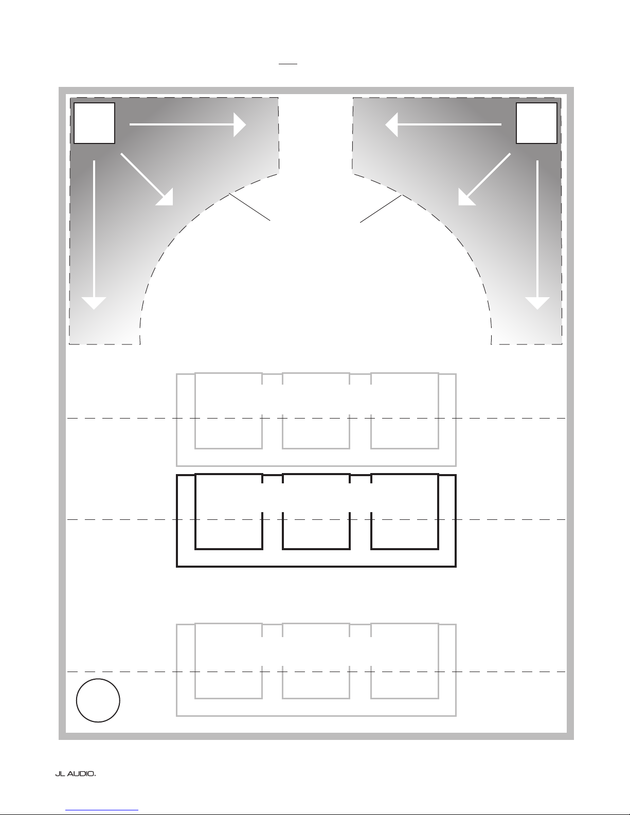
Recommended Subwoofer Placement Options for One Subwoofer
MORE INTENSE
SMOOTHER
SMOOTHER
SMOOTHER
RECOMMENDED
SUBWOOFER
PLACEMENT
ZONES
(For Single Subwoofer)
MORE INTENSE
SMOOTHER
SMOOTHER
SMOOTHER
COMPROMISED SEATING POSITIONS
(Results in weaker, uneven bass performance)
BEST SEATING POSITIONS
(Most accurate bass performance)
COMPROMISED SEATING POSITIONS
(More intense, but less accurate bass performance)
CENTERLINE OF ROOM
APPROX. 1/3 OF TOTAL ROOM
LENGTH AWAY FROM BACK WALL
CLOSE TO BACK WALL OF ROOM
WORST
SEAT
Page 7 | Fathom SA-600W
Page 8
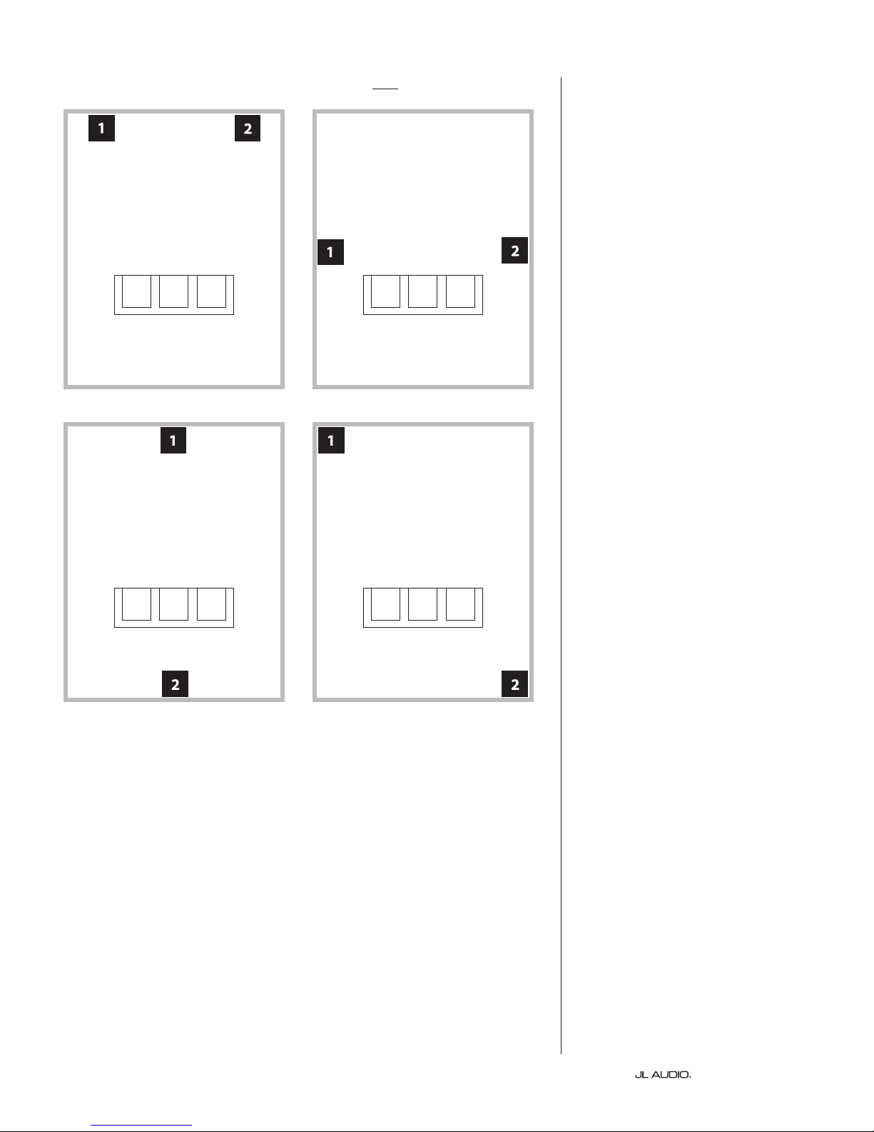
Recommended Subwoofer Placement Options for Two Subwoofers
Using Two Subwoofers
When using two subwoofers, try
placement near the front corners of the
room, at diagonally-opposite corners
of the room, or at the center points of
opposing walls as shown at right.
Experimentation with subwoofer
and listener placement is recommended
to achieve the best results – the benets
can be substantial.
High-resolution measurements
and professional system calibration
are recommended for the best possible
results & system performance.
| Fathom SA-600WPage 8
Page 9

Using Three or Four Subwoofers
Research indicates that the
smoothest bass response for a large
listening area can be achieved using
four subwoofers, placing one at
the midpoint of each of the four
walls (although using two or three
subwoofers can be almost as good).
Experimentation with
subwoofer and listener placement
is recommended to achieve the
best results – the benets can be
substantial.
High-resolution measurements
and professional system calibration
are recommended for the best possible
results & system performance.
Recommended Subwoofer Placement Options for Three Subwoofers
Recommended Subwoofer Placement Options for Four Subwoofers
Page 9 | Fathom SA-600W
Page 10
PLACEMENT CONSIDERATIONS
e SA-600W is designed to be “built-in” friendly. All typically needed
controls are located on the front panel. An SA-600W can be easily integrated into
an equipment rack or custom cabinetry by following a few simple guidelines.
1) Allow adequate open space around the SA-600W’s side-mounted heatsinks for
adequate cooling. Also allow space behind the amp for connector clearance.
2) While the SA-600W generally runs only warm during spirited operation, we do
recommend that adequate heat vents are included in any custom cabinet which
encloses the SA-600W. A pair of 3 inch (7.5 cm) diameter vents near the bottom
of the cabinet and near the top of the cabinet, will allow cool air to circulate over
the heatsinks of your SA-600W keeping it cool and happy.
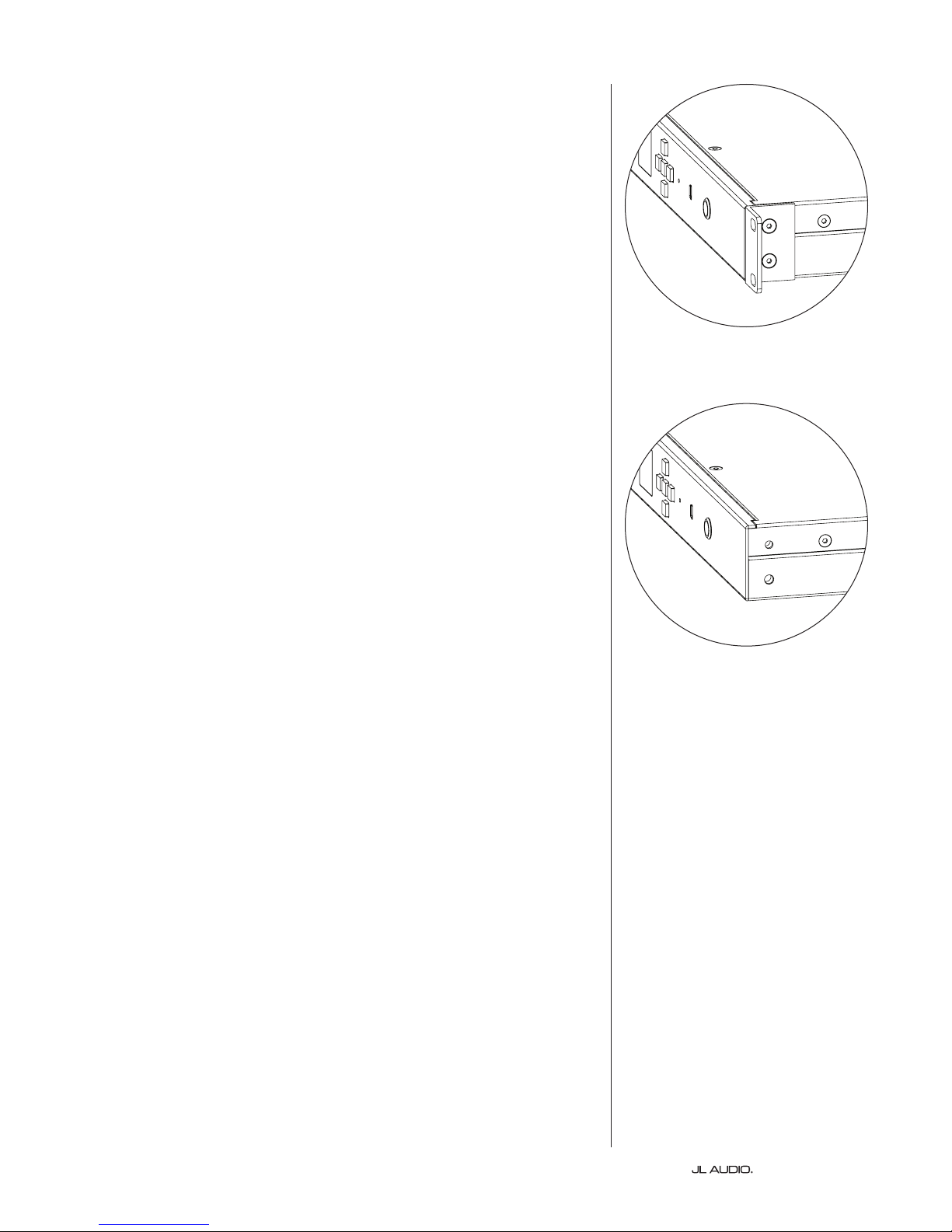
Rack Mount: e SA-600W ships with rack ears pre-attached for installation in a
standard 19-inch equipment rack.
Tabl e -Top: e SA-600W includes rubber feet for table-top installations.
Simply remove the hex screws that attach the rack ears to the SA-600W
and screw the rubber feet into threaded holes in the bottom of the amplier
case. WARNING: e rubber feet attach using M6-1.0 x 10mm screws. If
lost or misplaced, only replace with the same type and length of screws.
Using longer screws will cause damage to the internal circuit board.
Rack Mount
Tabl e -Top
| Fathom SA-600WPage 10
Page 11
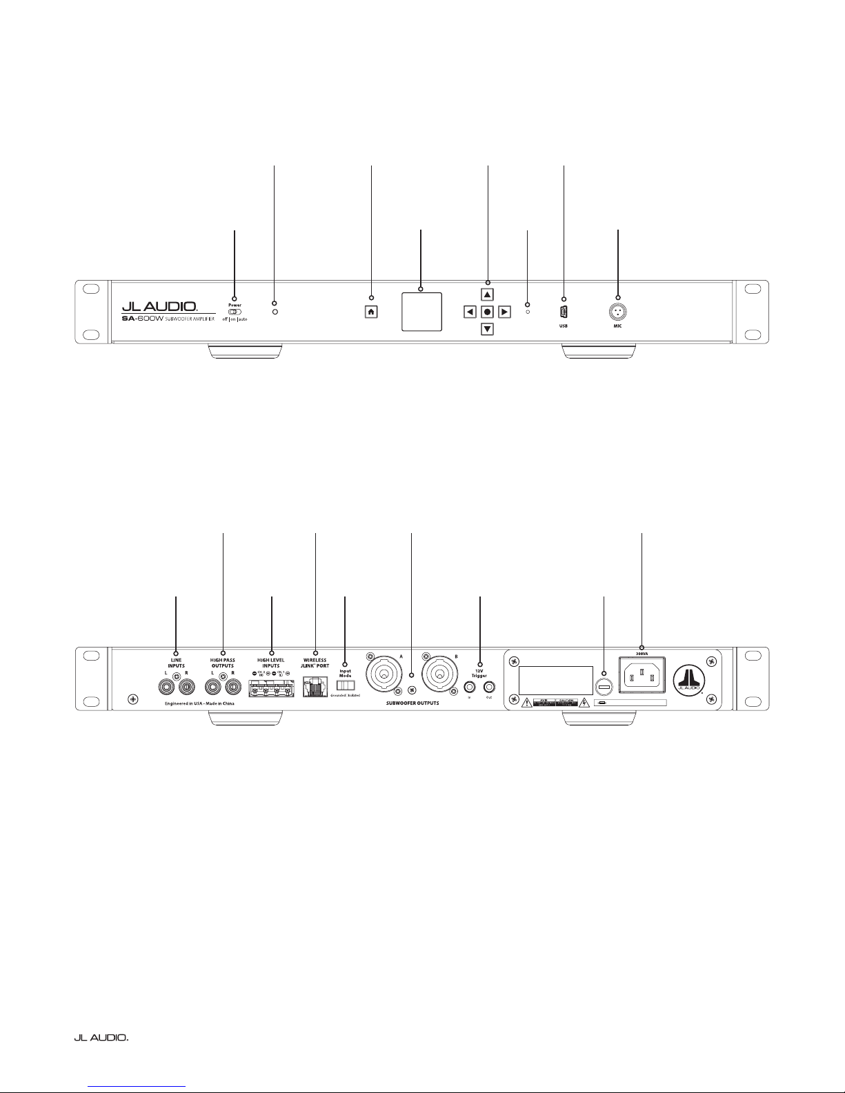
Front Control Panel
Rear Connector Panel
Power
page 12
High Pass
Outputs
page 14
LED Status
Indicator
page 12
Wireless
JLINK
page 15
™
Port
Home
Button
page 13
LCD Display
page 13
Subwoofer
Outputs
page 16
5-Way
Control Pad
page 13
DFU
Button
page 13
USB
page 13
MIC
page 13
IEC-Style AC
Connector
page 17
Line Inputs
page 14
High Level
Inputs
page 15
Input Mode
Switch
page 16
12V Tr igger
page 17
Warranty void if serial number is removed, altered or defaced.
Main Fuse
page 17
S
E
U
F
F
U
E
S
120 V ~ 60 HzF 6A H 250V
Page 11 | Fathom SA-600W
Page 12
FRONT PANEL CONTROLS IN DETAIL
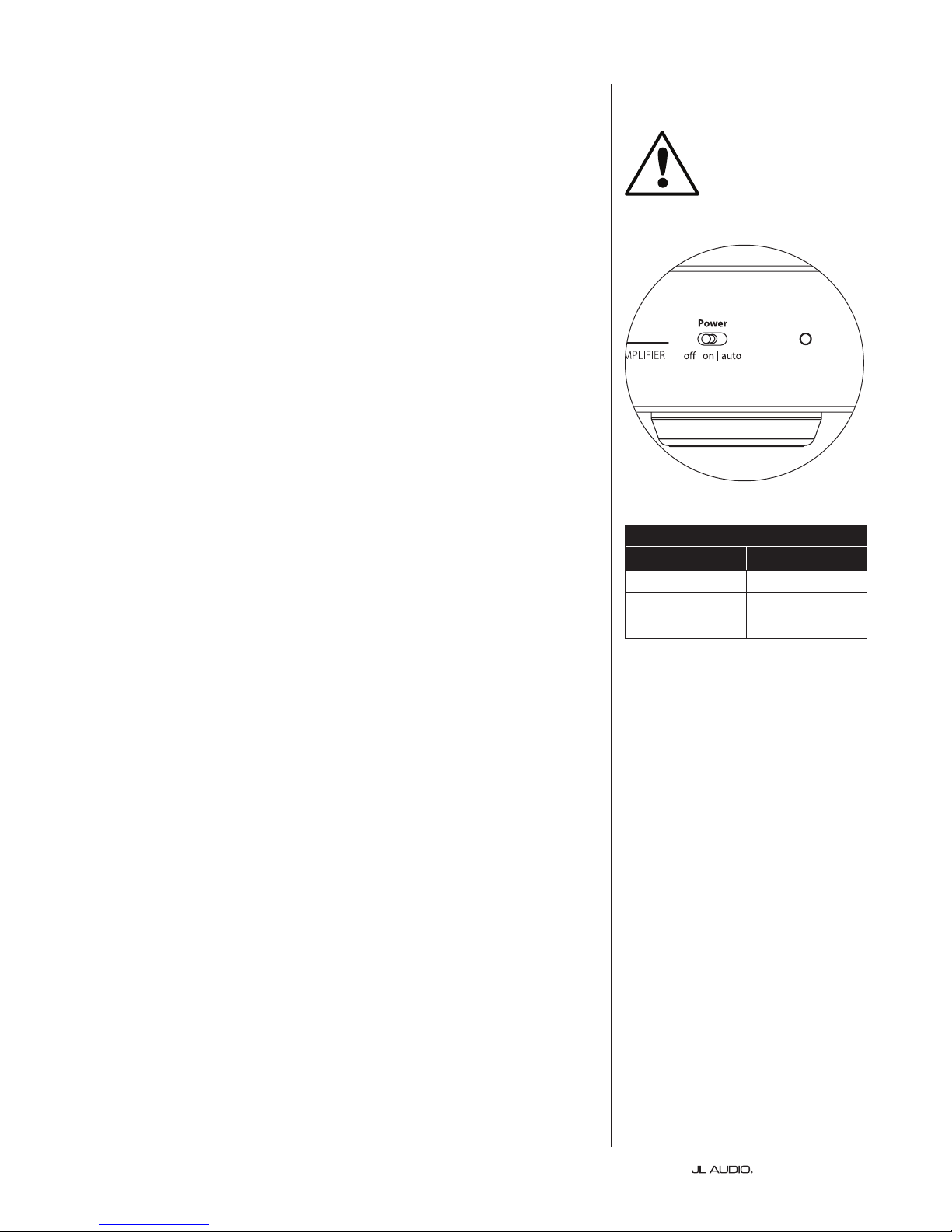
Power Switch
e “Power” switch determines the operational readiness of the SA-600W and
should be the only method used to turn the amplier on and o. Do not use a power
strip switch, switched outlet or any other external switch as these may result in
undesirable and potentially damaging transient pops. Do not unplug the SA-600W’s
AC power cord while the unit is turned on.
The Power switch has three positions:
“o ”: e SA-600W is powered down. In this state, a negligible current draw
will exist for operating the main power relays. e front panel LED is RED and
the LCD Display is dim with the message “In Standby. Power switch is OFF.”
displayed.
“on”: e SA-600W is fully powered at all times. e front panel LED is GREEN
and the Home Screen menu options are listed on the LCD Display.
“auto”: In this position, the SA-600W can be activated by the following methods:
Signal Sensing: In this default mode, the SA-600W will power up when an audio
signal is present at any of its inputs and will power down its internal amplier
when no signal has been detected at its inputs for sixty (60) minutes. When
dormant, the SA-600W will draw a minimal amount of current (< 1 watt) to
power its Signal-Sensing circuitry. e front panel LED turns YELLOW when the
SA-600W powers down to indicate Standby mode and the LCD Display will show
“In Standby. Waiting for audio input.” e front panel LED will turn GREEN
when the SA-600W powers up.
Note: In the unlikely event that the auto Signal-Sensing feature is not sensitive
enough for a particular system, use a Y-adaptor cable (one female to two male
RCA-type connectors) to split the incoming signal into both RCA line inputs on
the SA-600W. is will increase the input sensitivity by 6 dB. Please be aware
that if there is signicant noise entering the inputs, the SA-600W may not turn
o as desired. If this happens, remove the Y-adaptor cable and/or look for the
noise source in the upstream components.
IMP ORTANT
LED Status Indicator
Color Mode
Red O
Green On
Yellow Standby
12V Trigger: Optionally, the SA-600W can be activated using a 12V DC signal.
To enable this mode, select “SYSTEM” on the Home Screen screen (see page 18
for more info) and select “12V ON”. is setting overrides audio Signal-Sensing
and will only turn on the SA-600W when a 12V DC signal is present at its
“12V Trigger - In” connection. When the 12V DC signal is removed from
the “12V Trigger - In” connection, the SA-600W will enter Standby mode
immediately, the front panel LED turns YELLOW and “In standby. Waiting for
12V trigger.” will be shown on the LCD Display.
Note: Whenever the SA-600W is ON, its “12V Trigger - Out” output will be
active, regardless of the “SYSTEM” setting. is allows you to control multiple
SA-600Ws using a single 12V trigger lead by daisy-chaining them together (“12V
Trigger - Out” activates the “12V Trigger - In” of the next amp, etc.).
| Fathom SA-600WPage 12
Page 13

User Interface Controls (Home Button, LCD Display and 5-Way Control Pad)
Accessed via the Home Button, LCD Display and 5-Way Control Pad,
the SA-600W’s electronic interface delivers simple and intuitive user control over
all onboard settings and adjustments. Refer to pages 18-21 for detailed User
Interface info.
USB
e front panel “USB” port (Mini-B) is used for rmware updates only. Refer to
DFU BUTTON below for detailed info.
MIC
e mini-XLR jack on the front panel of the SA-600W is for connecting the
optional JL Audio D.A.R.O. Calibration Microphone (sold separately). Only the
ocial JL Audio D.A.R.O. Microphone will function properly when connected
to the front-panel “MIC” jack. e D.A.R.O. Microphone Kit can be ordered
separately from your JL Audio Dealer. Refer to D.A.R.O. (Digital Automatic Room
Optimization) on page 20 for detailed info.
DFU Button
Located in the small hole between the 5-Way Control Pad and the USB port, the
DFU button is used to activate the Device Firmware Upgrade (DFU) function.
To use, connect the SA-600W to a PC or laptop using a mini USB cable. en,
using the end of a paper clip, press and release the recessed button. All the lights
will turn o and the display will be blank. Now run the JL-Updater soware
and follow the on-screen instructions. Note: We recommend disconnecting the
“SUBWOOFER OUTPUTS” while updating rmware.
In case of communication failure, normal operation of the SA-600W can be
recovered with a power cycle by disconnecting and reconnecting the SA-600W’s AC
power cord. You should then contact JL Audio’s Home Technical Support Dept.
Page 13 | Fathom SA-600W
Page 14

CONNECTING YOUR SA-600W
Warranty void if serial number is removed, altered or defaced.
Warranty void if serial number is removed, altered or defaced.
Line Inputs
e SA-600W features individual le and right unbalanced RCA-type input
connectors. If you are connecting with a mono signal, use either the “L” or “R” input.
e SA-600W uses special isolation circuitry on the “LINE INPUTS” to mitigate
hum and noise in your system.
For the RCA connector, the tip is positive and the sleeve is negative. e input
impedance of the amplier is 50k ohms.
High Pass Outputs
e SA-600W features individual, le and right, unbalanced RCA-type output
connectors to feed a second amplier. ese outputs can be used in two distinct ways.
Crossover On: High-Pass Filtered Outputs
When the SA-600W’s onboard crossover is engaged, the “HIGH PASS
OUTPUTS” will deliver a high-pass ltered signal according to the frequency
and slope (12 or 24 dB per octave) congured in its crossover (XO) settings. is
output creates a true, two-way crossover between your subwoofer and main
stereo speakers. By removing low frequencies from the satellites, you
can create a seamless blend with your subwoofers, enhancing midrange
clarity and dynamics, with improved overall system response. is is
the correct way to add a subwoofer to your stereo system.
Note: You must supply separate le and right channel stereo inputs to the SA-
600W in order to have high-pass ltered, stereo outputs from its “HIGH PASS
OUTPUTS”. If you supply only one channel of input to the SA-600W, only the
line output corresponding to the input with signal will deliver a high-pass ltered
signal (the other line output will have no signal). If you are using two SA-600Ws
in a two-channel system, you can assign one SA-600W to the le stereo channel
and the other SA-600W to the right stereo channel, using only one “LINE
INPUT” and one “HIGH PASS OUTPUT” per SA-600W.
Crossover O: Pass-rough Outputs
When the SA-600W’s onboard crossover is defeated, the “HIGH PASS
OUTPUTS” will deliver a pass-through, buered signal that is identical to the
signal feeding the SA-600W’s “LINE INPUTS”. is is useful to feed other
equipment located nearby and most oen used in Home eater systems
where Bass Management is provided by the receiver or preamp/processor.
| Fathom SA-600WPage 14
Page 15

High level inputs
F
U
S
E
F
U
S
E
Warranty void if serial number is removed, altered or defaced.
120 V ~ 60 HzF 6A H 250V
F
U
S
E
F
U
S
E
Warranty void if serial number is removed, altered or defaced.
120 V ~ 60 HzF 6A H 250V
is feature is included for convenience when needing to connect the SA600W to a receiver that only oers speaker level outputs. It is not the preferred
method when a line-level signal is available.
To use this feature, simply connect the full-range speaker outputs of your
receiver to the “HIGH LEVEL INPUTS” plug of the SA-600W, in parallel with
the main speakers. In this application, the main speakers will remain full-range
and their sound will not be aected by the connection to the SA-600W.
e “HIGH LEVEL INPUTS” consists of an input connector and removable
plug with captured-wire receptacles. Standard speaker cable, up to 12 AWG (3
mm2), can be used and connected to the removable plug by backing out each set
screw, inserting the bare end of each speaker wire, taking care not to short any
wire to another, and tightening the set screw. Note: e mating connector is
keyed to t the input jack in one direction only.
“HIGH LEVEL INPUTS” connector (from le to right):
1. (-) Right Channel Negative
2. (+) Right Channel Positive
3. (-) Le Channel Negative
4. (+) Le Channel Positive
Input Impedance: 4.4 kΩ
Note: It is vital to observe correct electrical polarity of each channel’s
input signal. Failure to do so can result in no output, loss of signal and
poor performance.
Wireless JLINK™ Port
Your SA-600W includes a “WIRELESS JLINK™ PORT” receptacle that can be
used with a JL Audio JLINK™ TRX system (sold separately). e JLINK™ TRX is
a high-delity audio transmitter & receiver system, capable of wirelessly sending
audio signals up to 100 feet away (30 meters). Using a JLINK™ TRX will eliminate
the need to run physical signal cables from your receiver or preamp/processor’s
line-level outputs to the line-level inputs of your SA-600W. Instead, the SA-600W
will wirelessly receive audio signals into its “WIRELESS JLINK™ PORT” directly
from the JLINK™ receiver’s cable connection.
Note: Use of the JLINK™ TRX system requires line-level outputs from your
receiver or preamp/processor. Speaker level outputs are not compatible.
Page 15 | Fathom SA-600W
Page 16

Input Mode
F
U
S
E
F
U
S
E
Warranty void if serial number is removed, altered or defaced.
120 V ~ 60 HzF 6A H 250V
F
U
S
E
F
U
S
E
Warranty void if serial number is removed, altered or defaced.
120 V ~ 60 HzF 6A H 250V
is feature is included to address signal grounding issues oen encountered
in home theater systems when several components from dierent manufacturers
are interconnected. e Input Mode switch on the rear connection panel
alters only the “LINE INPUTS” and is designed to facilitate a quiet, hum-free
connection to your audio or home theater system. is switch has no eect on
signals connected to the “HIGH LEVEL INPUTS”.
e SA-600W ships with this switch in the “Isolated” position. If, with all
system components connected and turned on (but no source material playing),
you hear a continuous low-frequency hum through your SA-600W, move this
switch to the “Grounded” position and evaluate the dierence in the noise level.
Use whichever switch position provides the least hum or noise. Note: If you
change equipment or add equipment to your audio system, you may need to
revisit the “Input Mode” switch setting to achieve the quietest signal path.
Subwoofer Outputs
e SA-600W is equipped with a pair of Neutrik speakOn® jacks for speaker
connections. Both jacks (labeled A & B) are congured for 2 wire termination
(speaker + & speaker –) and are connected in parallel, inside the SA-600W, so you
can use either output when connecting a single subwoofer.
A pair of removable Neutrik speakOn® plugs (NL2FX) are supplied with the SA600W for making high-integrity connections. Each plug is keyed for insertion in the
rear “SUBWOOFER OUTPUT” jacks in one direction only. Once inserted, rotate
the plug 1/8 turn clockwise to lock in place. To disconnect, slide the thumb latch
back and rotate the plug 1/8 turn counter-clockwise to remove. Receptacles in each
plug accept 12 AWG to 16 AWG speaker wire. Each wire attaches to the terminals
marked “1–“ and “1+” (shown below).
To attach wires, insert the speaker cable through the strain relief and chuck. Strip
½ inch (12 mm) of insulation from the end of each wire, then use a small Philips
screwdriver to back out the set screws. Insert the bare wire into the receptacle,
seating it rmly so that no bare wire is exposed. While holding each wire in place,
tighten the set screw rmly, taking care not to strip the head of the screw.
Note: Use caution to ensure correct polarity and wire placement.
Slide the strain relief and chuck over the speaker cable, up to the plug body.
Align the chuck with the recesses in the plug body and tighten the strain relief onto
the plug body.
Plug Body
Wiring Detail
Speaker Cable
Chuck
Strain Relief
Plug Body
| Fathom SA-600WPage 16
Page 17

12V Trigger
F
U
S
E
F
U
S
E
120 V ~ 60 HzF 6A H 250V
S
E
F
U
S
120 V ~ 60 HzF 6A H 250V
F
U
S
E
F
U
S
E
Warranty void if serial number is removed, altered or defaced.
120 V ~ 60 HzF 6A H 250V
Equipped with dual mini jacks, the SA-600W can be activated using a 12V
trigger signal (Input) and turn on another component (or additional SA-600Ws)
any time the SA-600W is on (Output). Both jacks accept standard 1/8-inch (3.5
mm) plugs (not supplied), with +12V connected to the “tip” conductor and Ground
connected to the ring and/or sleeve conductor(s). Refer to 12V Trigger on page 12 for
more info.
Main Fuse Holder
Located on the rear panel, next to the AC cord receptacle is the main fuse
holder’s cover. is small spring-loaded cap may be removed, allowing access to
inspect or replace the main power fuse. If your AC outlet has power but the SA600W’s LED and LCD Display do not come on, the main power fuse may be blown.
To Remove - Unplug the SA-600W’s AC power cord. Insert a small athead
screwdriver into the cap’s slot and turn counter-clockwise slowly until the
fuse holder is released. Once removed, the fuse can be inspected and, if
necessary, replaced. Refer to the chart below for fuse values for your specic
SA-600W model.
To Reinstall - Note that the fuse holder’s body is keyed to the opening and
must be aligned to t properly. Insert the fuse holder into the opening and
gently turn clockwise (about 1/8 turn) to lock in place. Pressing the cap and
feeling for the spring to compress will help to locate the correct position.
Reconnect the AC power cord.
If the replacement fuse blows immediately aer replacing a fuse replacement,
the SA-600W may require service. Please contact your Authorized JL Audio
Retailer or Distributor.
Fuse Specications
Model Fuse Type Fuse Size
SA-600W (120V version) 0.25 x 1.25-inch, fast-acting 6A, 250V
SA-600W (240V version) 5mm x 20mm, fast-acting 4A, 250V
IEC-Style AC Connector
e IEC-style AC cord receptacle receives the heavy-gauge, 6 . (1.8 m) long,
power cord included with your SA-600W. Ampliers sold in dierent parts of the
world are congured for each market’s electrical system and include appropriate
plugs on the power cords. Please note the voltage markings next to the AC
Connector and make sure you are only powering the SA-600W from a receptacle
that matches these markings. Do not use any AC power cord other than the one
supplied with the SA-600W.
e SA-600W is a very powerful device and can draw a lot of current. If too
many components are connected with a SA-600W to one electrical outlet, you risk
tripping a household circuit breaker during very demanding program material.
If this happens, separate the SA-600W and other components between two AC
electrical circuits.
Page 17 | Fathom SA-600W
Page 18

HOME SCREEN & USER INTERFACE CONTROLS
12V ON
System Settings
12V OFF
Box EQ
V5.15 X144
System Reset
No EQ
IWS 8
12V ON
System Settings
12V OFF
Box EQ
V5.15 X144
CONFIRM RESET
V5.15 X144
No EQ
IWS 8
12V ON
System Settings
12V OFF
Box EQ
V5.15 X144
CONFIRM RESET
e SA-600W’s electronic user interface is controlled using the Home Button,
LCD Display and 5-Way Control Pad located on the front panel. Designed to be
simple and intuitive to use, all onboard adjustments can be made quickly and easily,
with just a few button presses.
All settings are accessed from the main Home Screen, with main menu options
appearing on the display while the SA-600W is powered on. You may return to the
Home Screen from any location within the interface by pressing the Home Button,
(located to the le of the LCD Display) to go back one step with each press.
e 5-Way Control Pad is to the right of the LCD Display. It consists of Up, Down,
Le, Right direction (arrow) keys, with a center Enter key. Generally speaking, use
the arrow keys to move/highlight your selection and then press the Enter key to
conrm your choice or access for further options.
Note: When settings are congured from their default state, the text of the
selected item and its main level option (except SYSTEM), will turn YELLOW to
indicate active mode.
USER INTERFACE IN DETAIL
SYSTEM
“SYSTEM” congures how your SA-600W is activated when the “Power” switch
is set to “auto” and allows access to the onboard equalizer settings.
auto mode options include:
12V OFF (default): Activates via Audio Signal Sensing
12V ON: Activates via “12V Trigger - In”
(see Power Switch on page 12 for detailed info)
HOME
SYSTEM
GAIN
POLAR
ELF
DARO
XO
Box EQ: is feature allows you to activate a preloaded EQ curve designed to
optimize the performance of a JL Audio subwoofer system. Simply select the
custom equalizer setting for your specic JL Audio subwoofer and enclosure. If
you are using a non-JL Audio subwoofer, you may select the “No EQ” option and
use the SA-600W’s 3-band EQ feature (page 21) to apply equalization, as needed.
System Reset: is feature allows you to quickly return all settings back to
a default state (O/Uncalibrated). Selecting “CONFIRM RESET” will erase
all saved congurations from the SA-600W’s intenal memory and perform
a soware reset. Note: If your SA-600W’s GAIN setting was previously
congured to variable (VAR), performing a System Reset will cause it to
revert to its default, Reference (REF) conguration. is may result in an
unexpected loud burst aer the SA-600W’s soware reset is complete.
Selecting “SYSTEM” will also list your SA-600W’s technical data at the bottom
of the LCD display. is information could be relevant in case your SA-600W
requires service.
12V OFF
DELAY
System Settings
12V ON
Box EQ
System Reset
EQ
| Fathom SA-600WPage 18
Page 19

12V ON
System Settings
12V OFF
Box EQ
V5.15 X144
ON
ELF Trim
OFF
0.0 dB
System Reset
No EQ
IWS 8
12V ON
System Settings
12V OFF
Box EQ
V5.15 X144
CONFIRM RESET
12V ON
12V OFF
Box EQ
V5.15 X144
ON
DARO
OFF
Uncalibrated
ON
DARO
OFF
Uncalibrated
Calibrate
Clear DARO
VAR
Gain
REF
0.0
dB
0.0
dB
ON
ELF Trim
OFF
0.0 dB
System Reset
No EQ
12V ON
12V OFF
Box EQ
V5.15 X144
CONFIRM RESET
ON
DARO
OFF
Uncalibrated
Calibrate
Clear DARO
Gain
REF
0.0
dB
Sub Polarity
0 deg
VAR
0.0
dB
180 deg
GAIN
“GAIN” allows you to congure the subwoofer output level, with two options.
REF: (default) e subwoofer level is xed at 0 dB (reference level).
is setting is useful if you are controlling the subwoofer level using a receiver
or preamp/processor.
VA R : e subwoofer level is variable and may be increased (+15 dB) or decreased
(-50 dB) in 0.50 dB steps, using the UP and DOWN arrow keys.
POLAR
“POLAR” allows you to select between normal (0 deg) and reversed (180 deg)
signal polarity and primarily aects the small frequency range around the crossover
point between your subwoofer and satellite speakers. is feature produces an
instantaneous reversal of the signal’s amplitude peaks.
When placing your subwoofer(s) in the room, either setting may provide a
smoother transition between your subwoofer(s) and satellite speakers. Use source
material with good mid and upper bass content for evaluation.
0 deg: (default) Normal polarity (0 deg)
Delay
OFF
HP Out
ON
Sub Out
0.0 0.0
ms
ms
DELAY
or to the “HIGH PASS OUTPUTS” of the SA-600W. e maximum delay available
is 25 milliseconds (in 0.1 ms increments). “DELAY” mode options include:
acoustic response at, the subwoofer output signal is naturally delayed - usually
on the order of 12 to 15 milliseconds. By delaying the satellite outputs by a similar
amount, you can achieve greater coherence, texture and punch through the crossover
region.
to atten the subwoofer’s acoustic response in your room. Satellite delay has little
audible eect if the frequency response through the crossover region is uneven.
180 deg: Polarity reversed 180 degrees
“DELAY” allows you to add time delay to either the “SUBWOOFER OUTPUTS”
HP Out: is control adds delay to the ltered satellite signal coming from
the SA-600W’s “HIGH PASS OUTPUTS” and can be very useful for helping
the subwoofer-to-satellite transition through the crossover region. Note: e
delay feature of the “HIGH PASS OUTPUTS” is available even if the onboard
crossover (XO) is not used (OFF).
Sub Out: is delay functions similar to a Phase control, adding delay to the
“SUBWOOFER OUTPUTS”.
Due to the built-in system equalization used to make the small-box subwoofer’s
Optimum DELAY results can be achieved by rst running the D.A.R.O. system
Page 19 | Fathom SA-600W
Page 20

ELF
12V ON
System Settings
12V OFF
Box EQ
V5.15 X144
System Reset
No EQ
IWS 8
12V ON
System Settings
12V OFF
Box EQ
V5.15 X144
CONFIRM RESET
No EQ
IWS 8
12V ON
System Settings
12V OFF
Box EQ
V5.15 X144
CONFIRM RESET
e “ELF” (Extreme Low Frequency) function allows the user to apply signal
equalization at 25 Hertz. You can cut the signal at 25 Hz by 12 dB or boost the
signal at 25 Hz by 3 dB (0.5 dB increments). At 0 dB the equalizer is set at for zero
contribution to the signal. At maximum boost, the signal at 25 Hz is increased by 3
dB.
e ELF Trim feature is useful for tailoring a subwoofer system’s low frequency
output for your particular room. Adding some boost can make certain material
more exciting. Using the cut function can help to compensate for room or boundary
gain in the low frequencies. Room boundaries and the room’s nite (limited) size
naturally cause very low frequencies to be boosted relative to other parts of the
signal. As such, using the ELF Trim feature to cut the lowest frequencies can help to
tame “bloat” or unnatural sounding low bass in small to medium sized rooms (and
can also reduce unwanted vibrations in the room or throughout the house).
e “ELF” function aects frequencies 2 to 3 times higher than the 25 Hz
specication. is frequency tapering eect may reduce the overall output of the
subwoofer and require the user to increase the “GAIN” control aer adjusting the
ELF Trim.
ELF Trim
OFF
ON
0.0 dB
D.A.R.O.
A powerful feature of the SA-600W is the innovative Digital Automatic Room
Optimization (D.A.R.O.) technology. is one-touch system serves to eliminate
the largest acoustic response peaks in your home theater at the main listening seat,
greatly improving the in-room low-frequency response. Calibration of the D.A.R.O.
system is fully automated. Please consult the SETUP PROCEDURES section of this
manual on pages 28-35 for details on how to use the D.A.R.O. system.
e D.A.R.O. feature can be turned ON and OFF (default) from this screen. You
may also turn the D.A.R.O. feature ON and OFF even when Calibration data is not
present (no room EQ exists).
To perform a room Calibration, plug the JL Audio calibration microphone into
the front-panel “MIC” jack, select the “Calibrate” option and press Enter.
If the D.A.R.O. calibration has not yet been performed, the bottom-most text on
the D.A.R.O. screen will display “Uncalibrated”.
Once you perform an D.A.R.O. Calibration, this text will display “Calibrated”.
en at the bottom of the screen, you will have the option to “Clear DARO”. Once
selected, this text will change to “CONFIRM CLEAR” in RED. Once selected, the
D.A.R.O. calibration data is erased and the text indicators return to their default
state.
You can also elect to run a new calibration sequence without clearing the existing
data. e new EQ curve is saved in place of the old one. For detailed instructions on
the D.A.R.O., refer to Setup Procedures on pages 28-35.
DARO
OFF
Uncalibrated
Calibrate
Clear DARO
ON
| Fathom SA-600WPage 20
Page 21

180 deg
Sub Polarity
0 deg
ON
DARO
OFF
Uncalibrated
ON
DARO
OFF
Uncalibrated
Calibrate
Clear DARO
VAR
Gain
REF
0.0
dB
0.0
dB
ON
OFF
0.0 dB
180 deg
Sub Polarity
0 deg
ON
Delay
OFF
ON
OFF
Uncalibrated
ON
OFF
Uncalibrated
Calibrate
Clear DARO
24dB12dB
Crossover
OFF
79.9 Hz
ON
Delay
OFF
HP Out
ms
Sub Out
ms
0.0 0.0
180 deg
Sub Polarity
0 deg
ON
Delay
OFF
ON
Equalizer
OFF
SAVE CHANGES
CANCEL CHANGES
EQ 3EQ 2EQ 1
EQ Band 2
50.0 Hz
0.0 dB
0.7 Q
EQ Band 3
50.0 Hz
0.0 dB
0.7 Q
24dB12dB
Crossover
OFF
79.9 Hz
ON
Delay
OFF
HP Out
ms
Sub Out
ms
0.0 0.0
OFF
79.9 Hz
OFF
SAVE CHANGES
CANCEL CHANGES
50.0 Hz
0.0 dB
Crossover
Equalizer
EQ Band 1
0.7 Q
XO
24dB12dB
ON
EQ 3EQ 2EQ 1
600W’s outputs. is is most useful in a dedicated 2 channel system for proper
integration of your stereo satellites and subwoofer system.
connectors (HIGH PASS OUTPUTS) to feed a separate amplier powering your
main stereo speakers or a second SA-600W (with Crossover set to OFF.)
less frequency overlap between your satellites and subwoofer. Less overlap yields
less interference between the high and low frequency drivers, oering a smoother
frequency response.
from there. Avoid crossover frequencies below 60 Hz. Since you own a top-notch
subwoofer system, allow it to do its job and remove the low-frequency burden from
your satellites. Removing the low frequencies from your satellites will improve your
system’s dynamic range and clarify the satellite’s mid-range performance. Higher
crossover frequencies (above 120 Hz) can cause localization of the subwoofers due to
high-frequency bleed through.
EQ
address specic in-room response problems.
adjustments, use the UP and DOWN arrows to move between parameters, and use
the LEFT and RIGHT arrows to make numerical adjustments.
(Green) to save your adjustments, or “CANCEL CHANGES” (Red) to leave the EQs
in their previous state. If you did not alter any of the EQ parameters, the “SAVE
CHANGES” and “CANCEL CHANGES” buttons will remain greyed out.
the Home screen. If you press HOME without selecting “SAVE CHANGES”,
your adjustments will be discarded (the same as if you pressed the “CANCEL
CHANGES” button).
“XO” (Crossover) allows you to apply low pass and high pass lters to the SA-
e SA-600W also features individual, le and right, unbalanced RCA-type
OFF (default): e “High-Pass Outputs” are a buered duplicate of the input
signal (full range). ese outputs can be used to drive the inputs to another SA600W or other equipment.
ON: Enables selection of either a “12 dB” or “24 dB” per octave slope for the
internal lter and adjustable lter frequency (30 Hz to 130.1 Hz) using the UP
and DOWN arrow keys.
Generally speaking, the steeper slope (24 dB/octave) is preferred as this allows
As a rule of thumb, start at 80 Hz (79.9 Hz on the SA-600W) and experiment
e “EQ” (Equalizer) section gives you 3 fully-adjustable bands of equalization to
OFF (default): No EQ bands are in the signal path
ON: Allows application of up to three EQ bands to the signal path. To make
Each EQ band includes the following adjustable parameter ranges:
Frequency range: 20Hz to 160Hz | Frequency step: 1Hz
Gain range: +/-12.0 dB | Gain step: 0.2dB
Q range: 0.7 to 5.0 | Q step: 0.1
Before exiting the “EQUALIZER” menu, select either “SAVE CHANGES”
Once you have saved or canceled changes, press HOME again to return to
Page 21 | Fathom SA-60 0W
Page 22

PRE-AMPLIFIER
FRONT
RECEIVER / PROCESSOR
FRONT
PRE OUT
REAR CENTER
L
REAR
R
SUB
SYSTEM CONNECTION DIAGRAM 1:
One SA-600W to
Home Theater Receiver or
Home Theater Preamp/Processor
Most home theater receivers and
preamp/processors provide a single
(mono) subwoofer output. Using RCAtype cables, connect the mono subwoofer
output to the Le or Right “LINE INPUT”
of your SA-600W.
Now that your equipment is
connected, refer to pages 32-35 and follow
the directions for RECOMMENDED
HOME THEATER SETUP
PROCEDURES.
SA-600W REAR CONNECTIONS
WARNING! TURN OFF THE SA-600W AND ALL OTHER EQUIPMENT IN THE
SYSTEM BEFORE MAKING OR CHANGING ANY CONNECTIONS!
WARNING
| Fathom SA-600WPage 22
Page 23

SYSTEM CONNECTION DIAGRAM 2:
PRE-AMPLIFIER
RECEIVER / PROCESSOR
Multiple SA-600Ws to
Home Theater Receiver or
Home Theater Preamp/Processor
Multiple SA-600Ws can be connected
in a single home theater system when Bass
Management is provided by the receiver
or preamp/processor. (SA-600W crossover
set to OFF.)
Most home theater receivers and
preamp/processors provide a single
(mono) subwoofer output. Using RCAtype cables, connect the mono subwoofer
output to the Le or Right “LINE INPUT”
of the rst SA-600W.
Connect the “HIGH PASS OUTPUTS”
from the rst SA-600W to the “LINE
INPUTS” of the second SA-600W.
Subsequent SA-600Ws will be connected
in the same manner.
Now that your equipment is
connected, refer to pages 32-35 and follow
the directions for RECOMMENDED
HOME THEATER SETUP
PROCEDURES.
FRONT
FRONT
PRE OUT
REAR CENTER
L
REAR
R
SUB
SA-600W REAR CONNECTIONS
WARNING
SA-600W REAR CONNECTIONS
WARNING! TURN OFF THE SA-600W(S) AND ALL OTHER EQUIPMENT IN
THE SYSTEM BEFORE MAKING OR CHANGING ANY CONNECTIONS!
Page 23 | Fathom SA-60 0W
Page 24

PRE-AMPLIFIER
L R
OUTPUTS
SA-600W REAR CONNECTIONS
SYSTEM CONNECTION DIAGRAM 3:
One SA-600W to
Two-Channel Audio System
e SA-600W is great for use in twochannel audio systems due to its onboard
high-pass crossover.
Using RCA-type cables, connect the
Le and Right stereo outputs from your
preamp to the “LINE INPUTS” of your
SA-600W. is feeds a full-range stereo
signal into the amp.
Next, connect the Le and Right
“HIGH PASS OUTPUTS” from the
SA-600W to the Le and Right inputs
of your satellites’ stereo power amplier.
is will feed a high-passed ltered signal
(bass removed) to the Le and Right
speakers. Removing the bass burden from
your satellites will greatly enhance their
performance. See the XO discussion on
page 21 for additional info.
Now that your equipment is
connected, refer to pages 28-31 and follow
the directions for RECOMMENDED
STEREO SYSTEM SETUP
PROCEDURES.
INPUTS
L R
SATELLITE AMPLIFIER
SPEAKER OUTPUTS
L
+
–
R
+
–
(L) (R)
TO SATELLITE
SPEAKERS
SYSTEM BEFORE MAKING OR CHANGING ANY CONNECTIONS!
WARNING! TURN OFF THE SA-600W AND ALL OTHER EQUIPMENT IN THE
WARNING
| Fathom SA-600WPage 24
Page 25

SYSTEM CONNECTION DIAGRAM 4:
L R
OUTPUTS
PRE-AMPLIFIER
SATELLITE AMPLIFIER
RL
INPUTS
Two SA-600Ws to
Two-Channel Audio System
for Mono Bass
e SA-600W is great for use in twochannel audio systems due to its onboard
high-pass crossover. Mono bass in your
stereo system allows greater exibility in
subwoofer placement.
Using RCA-type cables, connect the
Le and Right stereo outputs from your
preamp to the Le and Right “LINE
INPUTS” of BOTH SA-600Ws. is feeds
a full-range stereo signal into BOTH
ampliers.
Next, connect the Le and Right
“HIGH PASS OUTPUTS” from ONE SA600W (the easiest one to physically access)
to the Le and Right inputs of your
satellites’ stereo power amplier. is will
feed a high-passed ltered signal (bass
removed) to the Le and Right speakers
once the SA-600W’s internal crossover
(XO) is turned ON. Removing the bass
burden from your satellites will greatly
enhance their performance. See the XO
discussion on page 21 for additional info.
Now that your equipment is
connected, refer to pages 28-31 and follow
the directions for RECOMMENDED
STEREO SYSTEM SETUP
PROCEDURES.
Y-ADAPTOR
SA-600W REAR CONNECTIONS
WARNING
SA-600W REAR CONNECTIONS
WARNING! TURN OFF THE SA-600W(S) AND ALL OTHER EQUIPMENT IN
THE SYSTEM BEFORE MAKING OR CHANGING ANY CONNECTIONS!
Page 25 | Fathom SA-60 0W
Page 26

L R
OUTPUTS
RL
INPUTS
PRE-AMPLIFIER SATELLITE AMPLIFIER
SA-600W REAR CONNECTIONS (RIGHT)
SYSTEM CONNECTION DIAGRAM 5:
Two SA-600Ws to
Two-Channel Audio System
for Stereo Bass
e SA-600W is great for use in
two-channel audio systems due to its
onboard high-pass crossover. Stereo bass
can greatly enhance the imaging of your
system, however subwoofer placement
options can be limited (but it’s worth
the extra eort). With stereo bass, your
le and right subwoofers should be
placed nearby the le and right satellites,
respectively.
Using RCA-type cables, connect the
Le output of your preamp to the Le
“LINE INPUT” of one SA-600W and
the Right output from your preamp to
the Right “LINE INPUT” of the other
SA-600W. is feeds a full-range signal
to EACH amplier - one amp for the
Le channel and one amp for the Right
channel.
Next, connect the Le “HIGH PASS
OUTPUT” from the Le SA-600W to
the Le input of your satellite’s stereo
power amplier. en, connect the Right
“HIGH PASS OUTPUT” from the Right
SA-600W to the Right input of your
satellite’s stereo power amplier. is will
feed a high-passed ltered signal (bass
removed) to the Le and Right speakers
once the internal crossover (XO) is turned
ON. Removing the bass burden from
your satellites will greatly enhance their
performance. See the XO discussion on
page 21 for additional info.
Now that your equipment is
connected, refer to pages 28-31 and follow
the directions for RECOMMENDED
STEREO SYSTEM SETUP
PROCEDURES.
SA-600W REAR CONNECTIONS (LEFT)
WARNING! TURN OFF THE SA-600W AND ALL OTHER EQUIPMENT IN THE
SYSTEM BEFORE MAKING OR CHANGING ANY CONNECTIONS!
WARNING
| Fathom SA-600WPage 26
Page 27

SYSTEM CONNECTION DIAGRAM 6:
STEREO RECEIVER
Connecting one SA-600W to a
Receiver via the High Level Inputs
e SA-600W features high level
inputs designed to accept the output
of an amplied source, such as a stereo
receiver’s speaker outputs. e use of this
feature is only recommended when no
suitable line-level signal is available.
When connecting a single SA-600W
in mono to a two-channel receiver’s
speaker outputs, you will use both the
Le and Right connections on the “HIGH
LEVEL INPUTS” plug of the SA-600W.
Use good quality speaker cables (up to 12
AWG/3 mm2) to make these connections.
Make sure you capture all the wire strands
in each connector port and do not allow
any of these wires to short together.
You can make the connections to the
SA-600W’s “HIGH LEVEL INPUTS”
at the receiver’s output terminals, or
at the main speakers, whichever is
more convenient. On receivers with
A/B speaker circuit selectors, you can
connect the SA-600W to the “B” outputs,
giving you the ability to easily switch the
SA-600W’s signal on and o with the
receiver’s speaker circuit selector switch.
e input section of your SA-600W
will sum the le and right inputs to mono
and you may use its onboard crossover
(XO) to apply low-pass ltering. Because
the main speakers are being fed in parallel
with the “HIGH LEVEL INPUTS” of the
SA-600W, they continue to operate as fullrange speakers. Any adjustment to the
crossover function (XO) will only aect
the sound of the subwoofer(s) connected
to the SA-600W’s “SUBWOOFER
OUTPUTS”.
Note: It is vital to observe correct
electrical polarity of each channel’s
input signal. Failure to do so can
result in no output, loss of signal and
poor performance.
SPEAKER
OUTPUTS
L
+
–
(L) (R)
STEREO RECEIVER
–
TO SATELLITE
SPEAKERS
SPEAKER
OUTPUTS
+
L
–
–
+
R
HIGH LEVEL
INPUT PLUG
SA-600W REAR CONNECTIONS
OROR
+
R
TO SATELLITE
SPEAKERS
(R) (L)
HIGH LEVEL
INPUT PLUG
SA-600W REAR CONNECTIONS
Page 27 | Fathom SA-600W
Page 28

RECOMMENDED STEREO SYSTEM SETUP PROCEDURES
1) Preparation for Setup Process: ........................................ 28
2) Apply A.R.O: .................................................... 29-30
3) Level Setting: ....................................................... 30
4) Polarity/Delay Adjustment: ............................................31
5) Adjust E.L.F. Trim: ...................................................31
PREPARATION FOR STEREO SYSTEM SETUP:
Please conrm the following system settings before beginning the setup
process. is will ensure a neutral starting point and an eective setup of your
subwoofer system. NOTE: In this Stereo System setup process, we assume that
the SA-600W is handling bass management tasks.
On your Stereo Preamp:
Before beginning setup of your SA-600W we recommend that you set your
receiver or preamp/processor as follows:
1. Set Balance controls to Center.
2. Set all Tone controls to “0” and defeat all Equalizer features.
3. Defeat any secondary processing (DSP “enhancement” or room processing)
On the SA-600W:
Before beginning the stereo system setup procedure, ensure your SA-600W’s
controls are set to a neutral starting position.
1. Set GAIN to REF
2. Set POLAR to 0 deg
3. Set DELAY to OFF
4. Set ELF to OFF
5. Set XO to ON at 24dB, with a frequency of 80 Hz (79.9 Hz)
6. Set EQ to OFF
| Fathom SA-600WPage 28
Page 29

IMP ORTANT
STEREO SYSTEM SUBWOOFER SETUP
Once you have adjusted the controls on your stereo preamp and your
SA-600W to the above recommendations, you may apply the optional D.A.R.O.
(Digital Automatic Room Optimization) system to optimize performance.
Note: Use of the D.A.R.O. feature requires the optional JL Audio D.A.R.O.
Calibration Microphone (sold separately).
In some systems, the SA-600W amplier will be installed away from the
listening environment. For these cases, the D.A.R.O. microphone cable may
not be long enough to perform the Calibration.
To facilitate Calibration with the SA-600W amplier in the listening room,
a pair of alligator clips are included to connect to the subwoofer’s speaker
terminals. is will allow the user to temporarily connect the amplier to the
enclosure for Calibration, even aer the enclosure is permanently installed
in the wall cavity. To use, disconnect the enclosure’s speaker leads from the
subwoofer and use the alligator clips to connect the SA-600W’s outputs to the
subwoofer’s speaker terminals.
1) Applying Digital Automatic Room Optimization (D.A.R.O.)
You are now ready to apply the power of JL Audio’s exclusive Digital
Automatic Room Optimization (D.A.R.O.) system. is system will measure the
response of the subwoofer at your primary listening seat and apply a powerful
equalizer to tame the peaks caused by room modes, resulting in smoother, more
accurate bass performance.
IMPORTANT! MAKE SURE THE ROOM IS QUIET DURING D.A.R.O.
CALIBRATION! TURN OFF ANY NOISY APPLIANCES NEAR THE LISTENING
ROOM (DISHWASHERS, WASHING MACHINES, ETC.).
IT IS PARTICULARLY IMPORTANT TO TURN OFF AIR CONDITIONERS OR HEAT
PUMPS DURING CALIBRATION. THESE FORCED-AIR-TYPE HVAC SYSTEMS
CAN CREATE MODERATE LEVELS OF 15 – 20 HZ NOISE THAT MAY INTERFERE
WITH CALIBRATION.
a) Set the “Power” switch to the “on” position.
b) Remove the calibration microphone from its protective pouch and connect
its cable to the “MIC” jack on the SA-600W’s front control panel.
Note: D.A.R.O. Calibration is only possible when the JL Audio test
microphone is plugged in to the SA-600W front panel. e “Calibrate” feature
is disabled with no microphone plugged in to prevent accidental loss of
settings.
c) Connect the microphone to the other end of the mic cable and temporarily
place the mic in the primary listening seat. If you have a microphone stand,
you can place the microphone at head height and position in the primary
listening seat.
d) From the SA-600W’s User Interface, go to “DARO”, select “ON”, then
select “Calibrate”. A 5 second countdown will begin with “Position Mic”
displayed, indicating that the Calibration routine will begin in 5 seconds.
Page 29 | Fathom SA-600W
Page 30

e) Within 5 seconds of selecting “Calibrate”, return to your primary listening
seat and hold the microphone in your normal, seated head position at the
approximate height of your ears.
f) A low rumbling noise sequence will be played through the subwoofer
system that sounds like distant thunder. e sequence will last
approximately 3 minutes. During this process, the D.A.R.O. system is
taking a frequency response measurement at your seat and correcting
the problems it nds. e D.A.R.O. system also compensates for any
before & aer level dierences so that your subwoofer will have a similar
perceived loudness aer the calibration process. When D.A.R.O. is nished
calibrating, the “Calibrate” button will turn grey and the word “Calibrated”
will appear in green underneath, indicating a successful calibration.
To clear the D.A.R.O. settings (i.e., return them to at) & turn o the
“Calibrated” indication, select “Clear DARO”, then select “CONFIRM
CLEAR” to verify.
Should you wish to run a completely new calibration, simply repeat
Steps A-F. ere is no need to erase the old calibration rst. Any new calibration
will overwrite the existing data.
IMPORTANT! IF YOU MOVE YOUR PRIMARY LISTENING SEAT IN THE
FUTURE, YOU WILL NEED TO RUN D.A.R.O. AGAIN. ANY PARTICULAR
CALIBRATION IS UNIQUE TO THAT PARTICULAR SUBWOOFER POSITION
AND LISTENING SEAT POSITION COMBINATION.
2) Level Setting (GAIN)
Using familiar music material with deep bass content, adjust the subwoofer level
to blend with the other speakers using the Variable “GAIN” function on the SA600W. e subwoofer output level can be raised by up to 15 dB and can be attenuated
by 30+ dB, if needed.
We recommend starting with the bass level a little bit too low and then, carefully
raising the subwoofer output bit by bit until a perfect balance is achieved.
Inadvertently having the bass too loud (even a couple of dBs) can mask midbass detail.
3) Polarity
It is oen helpful to have a second person operating these controls so that you
can easily hear the changes from the primary listening seat.
Listening to familiar source material (preferably music with good upper bass and
midbass response), switch the “POLARITY” from “0 deg” to “180 deg” and listen for
dierences. is eect will be most noticeable in the small frequency region around
the crossover point. e correct setting will sound most natural with the best upper
bass punch and articulation. If both sound similar, choose “0”.
IMP ORTANT
| Fathom SA-600WPage 30
Page 31

4) DELAY (Phase) Adjustment
Now using the same music material, audition dierent “HP out DELAY” settings
and choose the delay that further enhances the upper and midbass response. Delay
is given in milliseconds.
When connected to a JL Audio subwoofer, we recommend starting with 10
milliseconds of HP out delay, which compensates for the small delay inherent in
the SA-600W’s built-in, box-correction EQ lter. Experiment with times just above
and below the 10 millisecond mark, perhaps up to approximately 14 milliseconds.
Choose the setting that most enhances the crossover region’s response (subwoofer
and satellite playing together).
If you cannot hear a dierence in the various “HP out DELAY” settings, leave the
control at 10 milliseconds.
5) ELF Adjustment (Extreme Low Frequency Trim)
Use the “ELF” control to adjust the extreme low bass extension of the SA-600W.
is control allows -12 dB of cut or +3 dB of boost at 25 Hertz and is particularly
useful when using a subwoofer (or two) in a small to medium sized home theater.
Since smaller enclosed spaces help to boost the level of the lowest bass frequencies,
smaller theaters can be overwhelmed by the strong low-bass output of the subwoofer.
is can create a “thick” or “bloated” character in the lower bass region. Turning
down the “ELF” cuts the extreme low bass level and alleviates this condition. Feel
free to experiment and listen to a variety of demanding material until you nd the
best match for your room and your tastes.
Your SA-600W is now optimized for maximum bass performance at your
preferred listening seat. Congratulations!
Use pages 38-39 to record your amplier settings for future reference.
Page 31 | Fathom SA-60 0W
Page 32

RECOMMENDED HOME THEATER SETUP PROCEDURES
1) Preparation for Setup Process: ........................................ 32
2) Apply A.R.O: .................................................... 33-34
3) Level Setting: ....................................................... 34
4) Polarity/Delay Adjustment: ........................................... 34
5) Adjust E.L.F. Trim: .................................................. 35
PREPARATION FOR HOME THEATER SETUP:
Please conrm the following system settings before beginning the setup
process. is will ensure a neutral starting point and an eective setup of your
subwoofer system. NOTE: In this Home eater setup process, we assume
that the receiver or processor is handling bass management tasks (see Step 1
below).
On your Home Theater Receiver or Processor:
Before beginning setup of your SA-600W, we recommend that you set your
receiver or preamp/processor as follows:
1. Speaker Size: In the speaker setup menu of your receiver or processor, set up
all of your high-frequency speakers as “small” with a crossover point of 80 Hz.
is will send ALL bass to the SA-600W.
2. Speaker Distance: In the speaker setup menu, properly set all speaker
distances to the primary listening seat, including the subwoofer’s distance. Use
a tape measure to determine these distances (time coherence is important.)
If multiple subwoofers are being used, average their distances to the primary
listening seat and use that number to set the subwoofer distance.
3. Subwoofer Level: Set the subwoofer level in the receiver or processor to “0” or
its middle position.
4. Tone Controls/Equalizers: Set all tone controls to “0” and defeat all equalizer
features.
On the SA-600W:
Before beginning the home theater setup procedure, ensure your SA-600W’s
controls are set to a neutral starting position.
1. Set GAIN to REF
2. Set POLAR to 0 deg
3. Set DELAY to OFF
4. Set ELF to OFF
5. Set XO to OFF (crossover function is handled by your receiver/HT processor)
6. Set EQ to OFF
| Fathom SA-600WPage 32
Page 33

HOME THEATER SUBWOOFER SETUP
Once you have adjusted the controls on your home theater receiver or preamp/
processor and your SA-600W to the above recommendations, you may apply the
optional D.A.R.O. (Digital Automatic Room Optimization) system to optimize
performance. Note: Use of the D.A.R.O. feature requires the optional JL Audio
D.A.R.O. Calibration Microphone (sold separately).
In some systems, the SA-600W amplier will be installed away from the
listening environment. For these cases, the D.A.R.O. microphone cable may
not be long enough to perform the Calibration.
To facilitate Calibration with the SA-600W amplier in the listening room,
a pair of alligator clips are included to connect to the subwoofer’s speaker
terminals. is will allow the user to temporarily connect the amplier to the
enclosure for Calibration, even aer the enclosure is permanently installed
in the wall cavity. To use, disconnect the enclosure’s speaker leads from the
subwoofer and use the alligator clips to connect the SA-600W’s outputs to the
subwoofer’s speaker terminals.
1) Applying Digital Automatic Room Optimization (D.A.R.O.)
You are now ready to apply the power of JL Audio’s exclusive Digital
Automatic Room Optimization (D.A.R.O.) system. is system will measure the
response of the subwoofer at your primary listening seat and apply a powerful
equalizer to tame the peaks caused by room modes, resulting in smoother, more
accurate bass performance.
a) Set the “Power” switch to the “on” position.
b) Remove the calibration microphone from its protective pouch and connect
its cable to the “MIC” jack on the SA-600W’s front control panel.
Note: D.A.R.O. Calibration is only possible when the JL Audio test
microphone is plugged in to the SA-600W front panel. e “Calibrate” feature
is disabled with no microphone plugged in to prevent accidental loss of
settings.
c) Connect the microphone to the other end of the mic cable and temporarily
place the mic in the primary listening seat. If you have a microphone stand,
you can place the microphone at head height and position in the primary
listening seat.
d) From the SA-600W’s User Interface, go to “DARO”, select “ON”, then
select “Calibrate”. A 5 second countdown will begin with “Position Mic”
displayed, indicating that the Calibration routine will begin in 5 seconds.
e) Within 5 seconds of selecting “Calibrate”, return to your primary listening
seat and hold the microphone in your normal, seated head position at the
approximate height of your ears.
Page 33 | Fathom SA-60 0W
Page 34

f) A low rumbling noise sequence will be played through the subwoofer
system that sounds like distant thunder. e sequence will last
approximately 3 minutes. During this process, the D.A.R.O. system is
taking a frequency response measurement at your seat and correcting
the problems it nds. e D.A.R.O. system also compensates for any
before & aer level dierences so that your subwoofer will have a similar
perceived loudness aer the calibration process. When D.A.R.O. is nished
calibrating, the “Calibrate” button will turn grey and the word “Calibrated”
will appear in green underneath, indicating a successful calibration.
To clear the D.A.R.O.’s settings (i.e., return them to at) & turn o the
“Calibrated” indication, select “Clear DARO”, then select “CONFIRM
CLEAR” to verify.
Should you wish to run a completely new calibration, simply repeat the steps
above. ere is no need to erase the old calibration rst. Any new calibration will
overwrite the existing data.
IMPORTANT! MAKE SURE THE ROOM IS QUIET DURING D.A.R.O.
CALIBRATION! TURN OFF ANY NOISY APPLIANCES NEAR THE LISTENING
ROOM (DISHWASHERS, WASHING MACHINES, ETC.).
IT IS PARTICULARLY IMPORTANT TO TURN OFF AIR CONDITIONERS OR HEAT
PUMPS DURING CALIBRATION. THESE FORCED-AIR-TYPE HVAC SYSTEMS
CAN CREATE MODERATE LEVELS OF 15 – 20 HZ NOISE THAT MAY INTERFERE
WITH CALIBRATION.
2) Level Setting (GAIN)
Using familiar music or movie material with deep bass content, adjust
the subwoofer level to blend with the other speakers using your receiver or
processor’s subwoofer level control. is method is more immune to tampering
than using the SA-600W’s “GAIN” control (think toddlers or curious visitors).
In the unlikely event that the subwoofer level control in your receiver or
processor cannot be turned up enough to level match the SA-600W, return that
control to “0”. en, switch the SA-600W’s GAIN mode to VAR (Variable). With
“0” as your reference point (REF mode gain and VAR “0” gain are identical), use
the “VAR” control to level match the subwoofer with the other speakers.
3) POLARITY and DELAY (Phase) Adjustment
It is oen helpful to have a second person operating these controls so that you
can easily hear the changes from the primary listening seat.
Listening to familiar source material (preferably music with good upper bass
and midbass response), switch the “POLARITY” from “0 deg” to “180 deg” and
listen for dierences. e correct setting will sound most natural with the best
upper bass punch and articulation. If both sound similar, choose “0”.
Once “POLARITY” is set, use the same music material to audition dierent
“Sub out DELAY” settings and choose the one that further enhances the
upper and midbass response. Delay is given in milliseconds. Note that the HP
out control only applies to the “HIGH PASS OUTPUTS” on the rear panel
(not applicable if only a sub is connected to the SA-600W). If you can’t hear a
dierence in various “DELAY” settings, set the control to “0.”
IMP ORTANT
| Fathom SA-600WPage 34
Page 35

4) ELF Adjustment (Extreme Low Frequency Trim)
Use the “ELF” control to adjust the extreme low bass extension of the SA600W. is control allows -12 dB of cut or +3 dB of boost at 25 Hertz and is
particularly useful when using a subwoofer (or two) in a small to medium sized
home theater. Since smaller enclosed spaces help to boost the level of the lowest
bass frequencies, smaller theaters can be overwhelmed by the strong low-bass
output of the subwoofer. is can create a “thick” or “bloated” character in
the lower bass region. Turning down the “ELF” cuts the extreme low bass level
and alleviates this condition. Feel free to experiment and listen to a variety of
demanding material until you nd the best match for your room and your tastes.
Your SA-600W is now optimized for maximum bass performance at your
preferred listening seat. Congratulations!
Use pages 38-39 to record your amplier settings for future reference.
Page 35 | Fathom SA-600W
Page 36

TROUBLESHOOTING
No sound from subwoofer.
1. Verify that the SA-600W is plugged in, turned “ON”, with the Home
Screen menu options displayed on the LCD Display. If the SA-600W
will not power up, check the circuit breaker that feeds its outlet.
2. Verify that your receiver’s subwoofer settings have not changed.
3. If your other speakers play, but the connected subwoofer does not, try changing
the signal cables that feed the SA-600W or the speaker cables connecting the
subwoofer to the SA-600W.
4. If using the High Level Inputs, verify the correct electrical polarity of each
channel’s input signal.
5. A Protection Mode message appears on the LCD display if the SA-600W’s internal
temperature exceeds maximum levels. is built-in safeguard disables the output
signal to prevent damage to internal circuitry. Typical causes for this condition
are poor air circulation, likely due to conned mounting locations, and should be
corrected. Once the temperature decreases to normal levels, the Protection Mode
will deactivate and the SA-600W will automatically resume normal operation.
6. If the problem persists, contact your dealer or JL Audio Technical Support
for assistance.
Weak sound or poor performance when using the High Level Inputs.
1. Verify the correct electrical polarity of each channel’s input signal.
e bass level has changed.
1. Make sure your GAIN settings on the SA-600W and the level settings on your
receiver/preamp/processor have not changed.
2. Verify that the ELF TRIM setting has not changed.
Hums or other unusual noises from your subwoofer.
1. See Input Mode discussion on page 16 of this manual, especially if any upstream
components, cables, etc., have recently changed.
2. Turn o the SA-600W, disconnect all its input and output signal cables, turn the
SA-600W back on. If the noise disappears, the noise is being caused elsewhere in
your system - reconnect cables one at a time to help locate the problem.
Bass sounds “muddy” or “too heavy”.
1. Try decreasing the 25 Hertz level using the ELF Trim control. Muddy bass can
sometimes be caused by too much low frequency output in a moderately sized
room.
2. Decrease the overall subwoofer level.
3. Verify your receiver’s subwoofer settings.
4. Try a dierent main listening seat location. Changing your seating location can
have a HUGE eect on how your system sounds. See the placement discussion on
pages 6-9 of this manual.
| Fathom SA-600WPage 36
Page 37

LIMITED WARRANTY / SERVICE INFORMATION
JL AUDIO warrants this product to be free of defects in materials and
workmanship for a period of three (3) years from the original date of purchase.
Damage caused by the following is not covered under warranty: accident,
misuse, abuse, product modication or neglect, failure to follow installation
instructions, unauthorized repair attempts, misrepresentations by the seller. is
warranty does not cover incidental or consequential damages and does not cover
the cost of removing or reinstalling the unit(s) or shipping the unit(s) to JL Audio
for service. Cosmetic damage due to accident or normal wear and tear is not
covered under warranty.
is warranty is not transferable and applies only to the original purchaser
of the product from an authorized JL AUDIO dealer. Warranty is voided if the
factory-applied product serial number is removed or defaced.
Should service be necessary under this warranty for any reason due to
manufacturing defect or malfunction, JL AUDIO will, at its discretion, repair or
replace the defective product with new or remanufactured product at no charge.
Any applicable implied warranties are limited in duration to the period of
the express warranty as provided herein beginning with the date of the original
purchase at retail, and no warranties, whether express or implied, shall apply
to this product thereaer. Some states do not allow limitations on implied
warranties, therefore these exclusions may not apply to you. is warranty gives
you specic legal rights, and you may also have other rights which vary from
state to state.
WARNING
WARNING: THIS PRODUCT CONTAINS NO USERSERVICEABLE PARTS.
PRODUC T IN WHICH DISASSEMBLY, REPAIR AND/OR MODIFICATION HAS
BEEN ATTEMPTED BY UNAUTHORIZED PARTIES WILL NOT BE COVERED
UNDER WARRANTY.
If you need service on your JL AUDIO product:
All warranty returns should be sent to JL AUDIO freight prepaid through
an authorized JL AUDIO dealer and must be accompanied by proof of purchase
(a copy of the original sales receipt). Direct returns from consumers or nonauthorized dealers will be refused unless specically authorized by JL AUDIO
with a valid return authorization number. Warranty expiration on products
returned without proof of purchase will be determined from the manufacturing
date code. Coverage may be invalidated as this date is previous to purchase date.
Return only defective components. Non-defective items received will be returned
freight-collect. Customer is responsible for shipping charges and insurance in
sending the product to JL AUDIO. Freight damage on returns is not covered
under warranty. Always include proof of purchase (sales receipt).
For Service Information in the U.S.A. please call:
JL Audio customer service:
(954) 443-1100 during normal business hours (Eastern Time)
JL Audio, Inc • 10369 North Commerce Parkway, Miramar, FL 33025
International Warranties:
Products purchased outside the United States of America are covered only by that
country’s distributor and not by JL Audio, Inc.
Page 37 | Fathom SA-600W
Page 38

SETTINGS / NOTES
Date: / /
Description:
System Settings: 12V OFF
Box EQ IWS-8
Other
No EQ
ELF Trim: OFF
ON
Gain: REF
VA R
Auto Room Opt: OFF
ON
12V ON
dB
.
dB
.
Sub Polarity: 0 deg
180 deg
Crossover: OFF
12dB
24dB
.
.
Delay: OFF
ON HP Out
Sub Out
EQ: OFF
ON Band 1
Hz
Hz
ms
.
ms
.
Hz Band 2
.
dB
.
Q
.
Hz Band 3
.
dB
.
Q
.
Hz
.
dB
.
Q
.
| Fathom SA-600WPage 38
Page 39

Date: / /
Description:
System Settings: 12V OFF
12V ON
Box EQ IWS-8
Other
No EQ
ELF Trim: OFF
ON
dB
.
Gain: REF
VA R
dB
.
Auto Room Opt: OFF
ON
Sub Polarity: 0 deg
180 deg
Crossover: OFF
12dB
24dB
.
.
Delay: OFF
ON HP Out
Sub Out
EQ: OFF
ON Band 1
Hz
Hz
ms
.
ms
.
Hz Band 2
.
dB
.
Q
.
Hz Band 3
.
dB
.
Q
.
Hz
.
dB
.
Q
.
Page 39 | Fathom SA-60 0W
Page 40

Specifications SA-600W
Frequency Response: 1 Hz - 800 Hz (–3dB)
Amplifier Power:
RMS short-term
Amplifier Net Weight: 13 lbs. (5.9 kg)
Table-Top Dimensions: (H) Height x (W) Width x (D) Depth
Rack-Mount Dimensions: (H) Height x (W) Width x (D) Depth
“JL Audio”, “Fathom IWS” and the JL Au dio logo are registere d trademarks of JL Aud io, Inc., “Ahead of the Curve” is a t rademark of JL Audio, Inc . Due to continuous
product development, all specifications are subject to change without notice.
©2017 JL Audio, Inc. • U.S. PATENTS: #5,734,734 #5,949,89 8 #6,118,884 #6, 229,902 #6,243,479 #6,294,959 #6,501,84 4 #6,496,590 #6, 441,685 #5,687,247 #6,219,431
#6,625,292 #D472, 891 #D480,709 Other U.S . & Foreign patents pendi ng. For more detaile d information please v isit us online at www.jlaudio.com.
Nor th Commerce Parkw ay • Miramar, Florida • • USA
Height Dime nsions DO NOT in clude feet
FRONT PANEL
BACK PANEL
TOP VIEW
300 watt s x 1 @ 6 Ω
600 wat ts x 1 @ 3 Ω
1.75 in. x 16.84 in. x 13.63 in.
44 mm x 428 mm x 346 m m
1.75 in. x 19.0 in. x 13.63 in.
44 mm x 483 mm x 3 46 mm
Warranty void if serial number is removed, altered or defaced.
S
E
U
F
F
U
E
S
120 V ~ 60 HzF 6A H 250V
09262017
FE ATUR ES
Unbalanced Inputs:
Stereo or Mono (two RCA jacks -
Input Impedance of 50k Ohms)
Speaker/High Level Inputs:
Stereo or Mono (removable plug -
Input Impedance of 4.4k Ohms)
Line Outputs:
Stereo or Mono (two RCA jacks -
Pass-rough or High-Pass)
Speaker Outputs:
Neutrik speakOn® 2-Pole Connectors
(uses Neutrik part: NL2FX)
Input Grounding:
Isolated or Grounded
Level Modes:
Reference (xed gain) or
Variable from -50dB to +15dB over
reference gain (0.5 dB increments)
Power Modes:
O, On or Automatic (Signal-Sensing or
12V Trigger)
Filter Modes:
O, 12 dB per octave or 24 dB per octave
(Low-Pass, with tracking High-Pass
Outputs)
Filter Cuto Frequency:
Variable from 30 Hz – 130.1 Hz
Polarity:
0 or 180 degrees
Delay:
Variable from 0 – 25 ms
(0.1 ms increments, Sub and HP outputs)
E.L.F. Trim:
Variable from –12 dB to +3 dB at 25 Hz
(0.5 dB increments)
Equalizer Bands:
3
Equalizer Frequency Range:
20 to 160 Hz (1 Hz increments)
Equalizer Gain Range:
-12 dB to +12 dB (0.2 dB increments)
Equalizer Q Range:
0.7 to 5.0 (0.1 increments)
12V Trigger Output Capacity:
150 mA (1/8-inch/3.5mm mini jack)
Digital Automatic Room Optimization
(D.A.R.O.)
Optional, requires laboratory-grade
calibration microphone (sold separately),
defeatable
Wireless Connectivity: Optional, JLINK
TRX System (sold separately)
 Loading...