

JL Audio FATHOM IWS-SYS-108, FATHOM IWS-SYS-208 Installation Manual

IWS-SYS-108
IWS-SYS-208
Enclosure Installation Manual


IMPORTANT SAFETY INSTRUCTIONS
1) Read the Instructions — All safety and operating instructions should be
read before the subwoofer is operated.
2) Retain the Instructions — ese instructions should be retained
for future reference.
3) Heed Warnings — All warnings in these instructions should be followed.
4) Water and Moisture — e enclosure and subwoofer should NOT be used
near water – for example, near a bathtub, washbowl, sink, laundry tub, in a
wet basement, near a swimming pool, etc.
5) Heat and Flames — e enclosure and subwoofer should be situated away
from heat sources such as radiators, heat registers, stoves, replaces, or other
devices which produce heat. Do not place candles nearby.
6) Object or Liquid Entry — Care should be taken so that objects do not fall
into and liquids are not spilled onto the enclosure, subwoofer or grille. Do not
expose to dripping or splashing from liquids. Do not place objects lled with
liquids nearby. For example: ower vases, beverages, liquid-fueled lamps, etc.
WARNING
7) Damage Requiring Service — e subwoofer should be serviced by qualied
service personnel when:
a. objects have fallen or liquid has been spilled into the subwoofer
b. the subwoofer has been exposed to rain
c. the subwoofer does not appear to operate normally or exhibits a marked
change in performance
d. the subwoofer driver’s cone and/or suspension has been
physically damaged
THIS SUBWOOFER IS CAPABLE OF PRODUCING VERY HIGH SOUND
PRESSURE LEVELS. PLEASE EXERCISE RESTRAINT IN ITS OPERATION TO
PROTECT YOUR HEARING FROM PERMANENT DAMAGE.
Page 3 | Fathom IWS

TABLE OF CONTENTS
Important Safety Instructions: ........................................... 3
Introduction and Overview: ............................................. 4
System Components: ................................................. 5 -7
Installation Hardware / Tools for Installation: ............................. 8
What’s In e Box?: .................................................... 9
Enclosure Installation Procedure: .................................... 10 -18
Notes: ................................................................ 19
Specications: ........................................................ 20
INTRODUCTION
ank you for choosing the JL Audio Fathom In-Wall Subwoofer System, also
known as the IWS.
is document contains detailed instructions for the installation of the Fathom
IWS enclosure. Since a portion of the enclosure will be inaccessible aer installation,
we strongly recommend reading these instructions completely before beginning the
installation process. Please note, these instructions are for the installation of one (1)
IWS enclosure. Simply repeat the steps to install additional enclosures.
FATHOM IWS SYSTEM OVERVIEW
e Fathom IWS is oered in two options:
- IWS-SYS-108 includes all elements for the installa tion of one (1) subwoofer.
- IWS-SYS-208 includes all elements for the installation of two (2) subwoofers.
Each Fathom IWS System consists of four elements:
IWS-SYS-108 IWS-SYS-208
(1) Enclosure (2) Enclosures
(1) Subwoofer (2) Subwoofers
(1) Grille Assembly (2) Grille Assemblies
(1) 300W Amplier (1) 600W Amplier
Each system includes specialized hardware to ensure proper installation.
| Fathom IWSPage 4
Spacers and
padding will vary to
ensure a proper t.
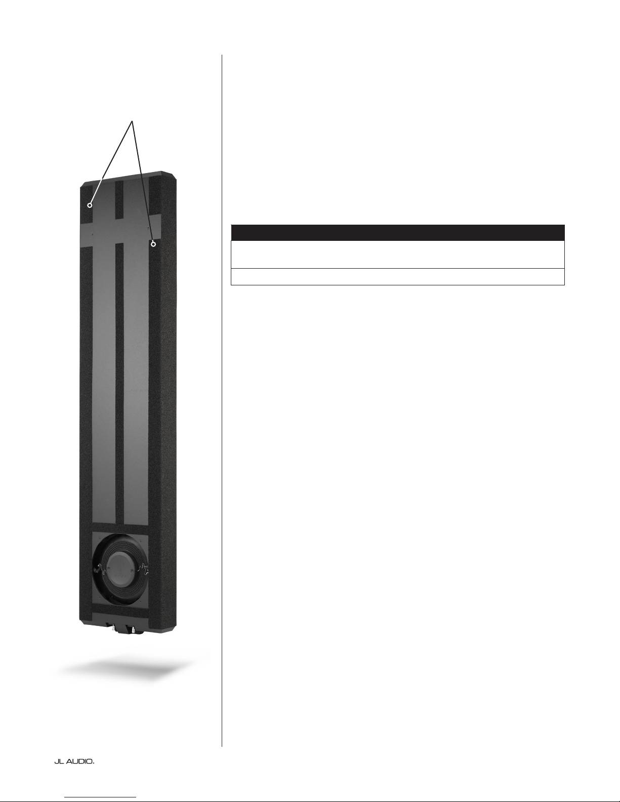
THE ENCLOSURE
e Fathom IWS enclosure utilizes extensive architectural features aimed at
improving rigidity while keeping a very low prole and minimal wall thickness.
A unique port design vents through a slot located at the perimeter of the driver
mount to enhance eciency and low-bass output. Designed to t snugly within
a 2 x 4 stud wall cavity, the enclosure has various spacers and padding applied
to specic areas, allowing it to only make gentle contact with its surrounding
wallboard surfaces. e placement and amount of pressure applied by these
pads is a critical design aspect to ensure proper t and should not be altered
in any way. Failure to use the proper enclosure and/or alteration of the spacers
and padding will result in loss of performance and unwanted wall vibrations.
Enclosure Dimensions*
61.26-inches x 14-inches x 3.25-inches
(1,565 mm x 355 mm x 83 mm)
*Dimensions listed are approximate and do not include various spacers and padding.
Page 5 | Fathom IWS
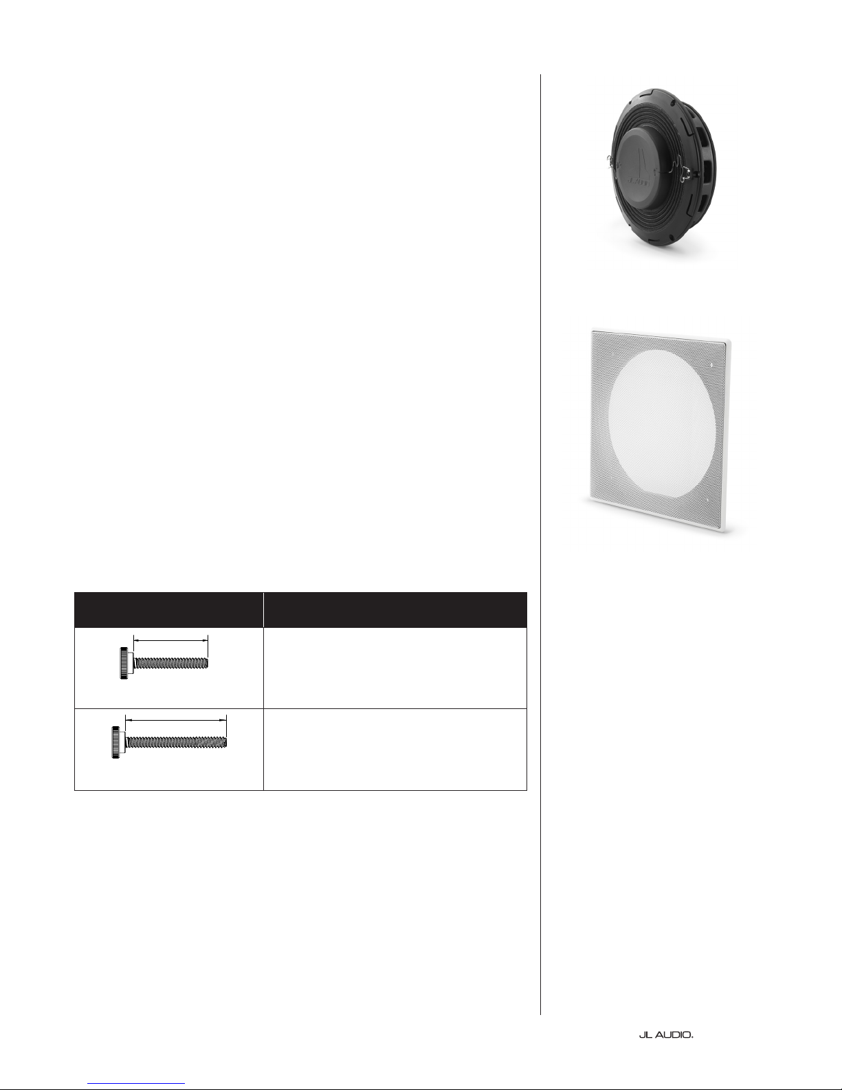
THE SUBWOOFER
1.75”
1.75”
2.5”
Derived from JL Audio’s groundbreaking technologies used to develop our
free-standing powered subwoofers, the Fathom® IWS in-wall subwoofer systems
deliver remarkable bass performance, while remaining largely concealed within
most home audio/theater environments. e 8-inch diameter driver is smaller
and easily integrates into all standard, 16-inch, on-center stud openings, and
operating through very small grilles.
THE GRILLE ASSEMBLY
e grille assembly is comprised of a removable outer metal mesh and
grille tray. e grille assembly should be installed only aer the surrounding
wallboard and grille assembly have been painted and the room’s interior is free
of construction debris. A plastic paint guard is included to shield the inner black
section of the grille tray from overspray during painting. e grille tray and
outer metal mesh grille should be painted separately to prevent them from
sticking together.
Two sets of dierent length thumb screws are included with the grille assembly
to t a range of wallboard thicknesses. It is critical to use the correct thumb screw
length for a proper t. Refer to the table at right to select the thumb screw length
that is compatible with the wallboard thickness used in your application.
Thumb Screw Length Wallboard Thickness
1/2 in. to less than 1-1/16 in.
13 mm to less than 27 mm
1/4-20 x 1.75 in.
1-1/16 in. to less than 1-3/4 in.
27 mm to less than 44 mm
1/4-20 x 2.5 in.
| Fathom IWSPage 6
 Loading...