

JL Audio Fathom IWS Installation Manual

Enclosure Installation Manual

NOTES
| Fathom IWSPage 2
IMPORTANT SAFETY INSTRUCTIONS
1) Read the Instructions — All safety and operating instructions should be
read before the subwoofer is operated.
2) Retain the Instructions — ese instructions should be retained
for future reference.
3) Heed Warnings — All warnings in these instructions should be followed.
4) Water and Moisture — e enclosure and subwoofer should NOT be used
near water – for example, near a bathtub, washbowl, sink, laundry tub, in a
wet basement, near a swimming pool, etc.
5) Heat and Flames — e enclosure and subwoofer should be situated away
from heat sources such as radiators, heat registers, stoves, replaces, or other
devices which produce heat. Do not place candles nearby.
6) Object or Liquid Entry — Care should be taken so that objects do not fall
into and liquids are not spilled onto the enclosure, subwoofer or grille. Do not
expose to dripping or splashing from liquids. Do not place objects lled with
liquids nearby. For example: ower vases, beverages, liquid-fueled lamps, etc.
WARNING
7) Damage Requiring Service — e subwoofer should be serviced by qualied
service personnel when:
a. objects have fallen or liquid has been spilled into the subwoofer
b. the subwoofer has been exposed to rain
c. the subwoofer does not appear to operate normally or exhibits a marked
change in performance
d. the subwoofer driver’s cone and/or suspension has been
physically damaged
THIS SUBWOOFER IS CAPABLE OF PRODUCING VERY HIGH SOUND
PRESSURE LEVELS. PLEASE EXERCISE RESTRAINT IN ITS OPERATION TO
PROTECT YOUR HEARING FROM PERMANENT DAMAGE.
Page 3 | Fathom IWS

TABLE OF CONTENTS
Important Safety Instructions: ......................................... 2-3
Introduction and Overview: ............................................. 4
System Components: ................................................. 5 -7
Installation Hardware / Tools for Installation: ............................. 8
What’s In e Box?: .................................................... 9
Enclosure Installation Procedure: .................................... 10 -17
Limited Warranty / Service Information: ................................. 19
Specications: ........................................................ 20
INTRODUCTION
ank you for choosing the JL Audio Fathom In-Wall Subwoofer System, also
known as the IWS.
is document contains detailed instructions for the installation of the Fathom
IWS enclosure. Since a portion of the enclosure will be inaccessible aer installation,
we strongly recommend reading these instructions completely before beginning the
installation process. Please note, these instructions are for the installation of one (1)
IWS enclosure. Simply repeat the steps to install additional enclosures.
FATHOM IWS SYSTEM OVERVIEW
e Fathom IWS is oered in two options:
- System One includes all elements for the installation of one (1) subwoofer.
- System Two includes all elements for the installation of two (2) subwoofers.
Each Fathom IWS System consists of four elements:
System One Syste m Two
(1) Enclosure (2) Enclosures
(1) Subwoofer (2) Subwoofers
(1) Grille Assembly (2) Grille Assemblies
(1) 1kW Amplier (1) 2kW Amplier
Each system includes specialized hardware to ensure proper installation.
| Fathom IWSPage 4
Spacers and
padding will vary to
ensure a proper t.
THE ENCLOSURE
e Fathom IWS enclosure is designed to suspend from a single anchor
point inside the wall cavity of 16-inch, on-center stud (aluminum or wood)
construction homes. Once installed, the enclosure will “hang” snugly within
the wall cavity. e enclosure has various spacers and padding applied to
specic areas, allowing it to only make gentle contact with its surrounding
wallboard surfaces. e placement and amount of pressure applied by these
pads is a critical design aspect to ensure proper t and should not be altered
in any way. Failure to use the proper enclosure and/or alteration of the spacers
and padding will result in loss of performance and unwanted wall vibrations.
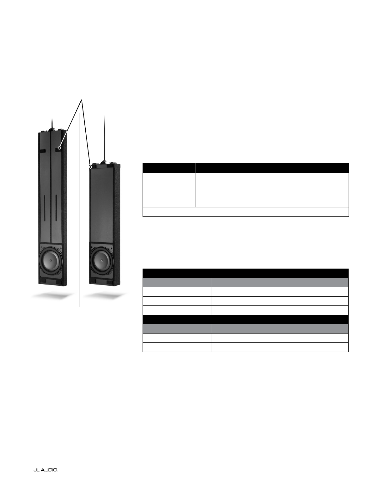
e Fathom IWS uses two enclosure types, referred to as the “A” box
and the “B” box. e “A” box is designed for 2 x 4 stud construction,
and the “B” box is designed for 2 x 6 stud construction.
Enclosure Type Enclosure Dimensions*
“A” Box
“B” Box
*Dimensions listed are approximate and do not include various spacers and padding.
70-inches x 13.75-inches x 2.9-inches
(1778 mm x 349 mm x 74 mm)
55-inches x 13.75-inches x 4.7-inches
(1397 mm x 349 mm x 119 mm)
“A” Box “B” Box
Furthermore, depending on the actual stud dimensions, there are variations
available for each enclosure type. We strongly recommend measuring your actual
stud dimensions to verify you have the correct enclosure for your application (see
char t below).
“A” Box Enclosure Variations for 2 x 4 Stud Construction
Actual Stud Width Enclosure Model SKU
3 1/2-inches (89 mm) IWEv2-113A-3.50 96093
3 5/8-inches (92 mm) IWEv2-113A-3.63 96094
4-inches (102 mm) IWEv2-113A-4.00 96095
“B” Box Enclosure Variations for 2 x 4 Stud Construction
Actual Stud Width Enclosure Model SKU
5 1/2-inches (140 mm) IWEv2-113B-5.50 96096
6-inches (152 mm) IWE v 2 -113 B -6. 0 0 96097
Page 5 | Fathom IWS
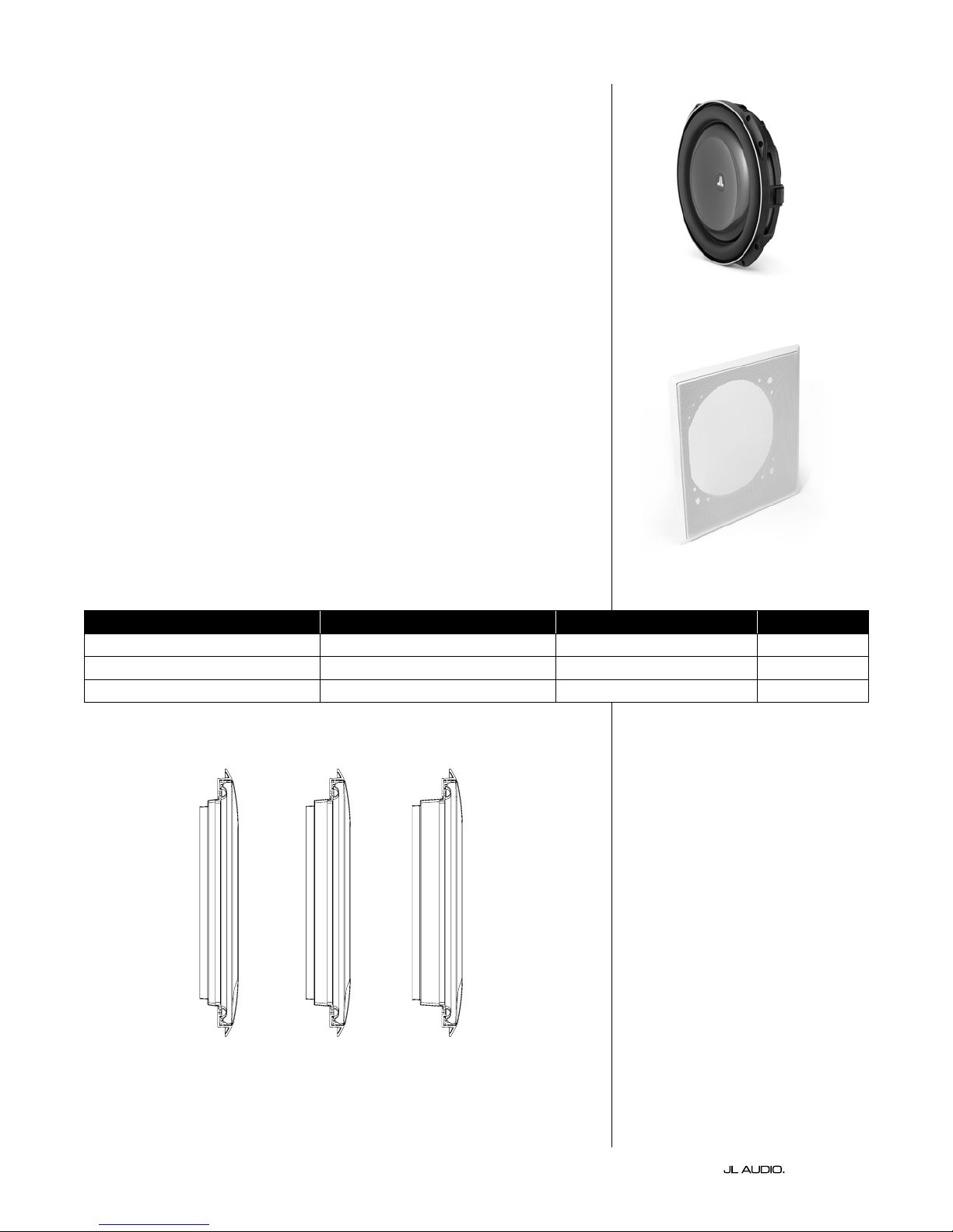
THE SUBWOOFER
Derived from JL Audio’s revolutionary TW5 design platform, the subwoofer
used in the Fathom IWS employs our patented thin-line woofer technology
to achieve extreme excursion capability and ultra-low frequency extension.
To reduce the possibility of damage during home construction or during the
enclosure’s installation process, the subwoofer is not pre-installed. e subwoofer
should only be installed aer all aspects of construction and wall nishing have
been completed.
THE GRILLE ASSEMBLY
e Fathom IWS enclosure uses a grille that mounts directly to the wall studs
instead of the enclosure. e grille assembly consists of a removable outer metal
mesh and grille tray unit. e grille’s design allows the enclosure to attach to the
wall without making actual hard contact with the enclosure itself.
is unique mounting method allows the enclosure to essentially “oat”
within the wall cavity without transferring vibrations to the wall itself. A plastic
paint guard is included to protect the woofer from overspray during painting. e
outer metal mesh and grille frame should be painted separately to prevent them
from sticking together.
e grille assembly is available in three size range options to accommodate
nine dierent wallboard thicknesses. It is critical to use the correct grille size
for proper t. Refer to the chart below to verify that your grille assembly is
compatible with the wallboard thickness used in your application. Do not
attempt to use or modify a grille that does not t your application.
Wallboard Thickness (inches) Wallboard Thickness (mm) Grille Assembly Model SKU
1/2” to less than 13/16” 12.7 mm to less than 20.6 mm IWG -113 -X 96090
13/16” to less than 1 3/16” 20.6 mm to less than 30.2 mm IWG -113-Y 96091
1 3/16” to less than 1 9/16” 30.2 mm to less than 39.7 mm IW G-113 -Z 96092
X Y Z
| Fathom IWSPage 6
 Loading...