

Page 1
DRC-205: Installation Instructions
Digital, Dual Rotary Controller For JL Audio Products
with JLid™ Compatibility
Connects to the JLid™ CTRL Port on VXi ampliers
or the JLid™ Port on TwK™ and FiX™ processors.
18 ft (5.5 m) CABLE
This product will not work with JL Audio amplifiers with
“Remote Level Control” or “Remote Bass Control Ports”.
Control Knob Installation:
1. Find an appropriate location to mount the Control
Knob assembly on the dash or console of the vehicle.
You will need access to the rear of the mounting
panel for installation.
The area will require the following minimum and
maximum dimensions:
Area Behind Panel: 1" square x 1" deep
(25mm x 25mm x 25mm)
Mounting Panel Thickness: 1/4 inch (6mm) maximum
2. Drill a 5/8” (16mm) hole in the center of the
mounting area.
3. Remove the knobs (inner, then outer) from the
controller’s shaft and remove the thumbnut from the
clear threaded sleeve.
4. From behind, insert the controller’s shaft through the
drilled hole and push forward.
5. From the front, hand-tighten the thumbnut onto
the clear threaded sleeve. Note: If needed, three
plastic spacers are included to adjust the overall
protrusion of the controller’s shaft. Depending
on mounting panel thickness and desired shaft
height, place 1, 2 or 3 spacers over the clear
threaded sleeve prior to performing step 4.
6. Turn each control fully counter-clockwise and place
the knobs on the shaft (outer, then inner) with their
markers pointing at 7:00.
7. Route one end of the control cable to the port of
a compatible JLid™-equipped device and connect
the other end to the harness jack of the DRC-205
controller.
8. Refer to the JLid™ product’s Owner’s Manual for the
specifics of control operation.
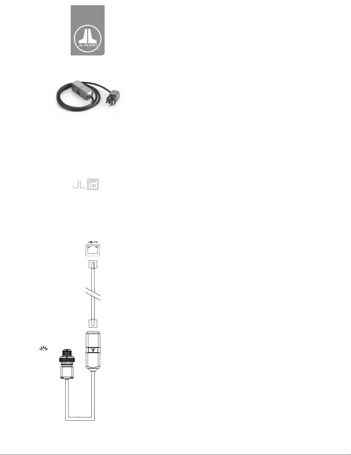
WITH
INTEGRATED
INDICATOR
LED
CONTROL
KNOB
Note: Components pictured may not be to scale.
HARNESS
JACK
Optional Mounting Clip Installation:
A mounting clip is included to secure the harness jack
module. Use the supplied screws to fasten the mounting clip
to a flat surface. Once the mounting clip is installed, attach
harness jack module by pressing one side of its notched
center section against the inside of one of the arms of the
mounting clip. Continue pressing inward until both arms of
the mounting clip snap around the notched center section
of the harness jack module. To remove, grasp the body of
the harness jack module and pull while rotating away from
the mounting clip.
Note: Should a replacement cable be needed, you may use any standard,
8-conductor network cable with RJ45 connectors. The arrangement
of the conductors at each connector end must be a “straight through”
conguration (pin 1 to pin 1, pin 2 to pin 2, etc.).
JL Audio® and th e JL Audio logo are registered trademark s of JL Audio, Inc. ©2018 JL Audio, Inc.
For more det ailed information please v isit us online at w ww.jlaudi o.com. Due to our p olicy of
continuous product development, all specications are subject to change without notice.
DRC205_MAN_05_30_18
 Loading...