

Page 1
OWNER’S MANUAL
6.50-inch (165 mm) Component Woofer
Page 2
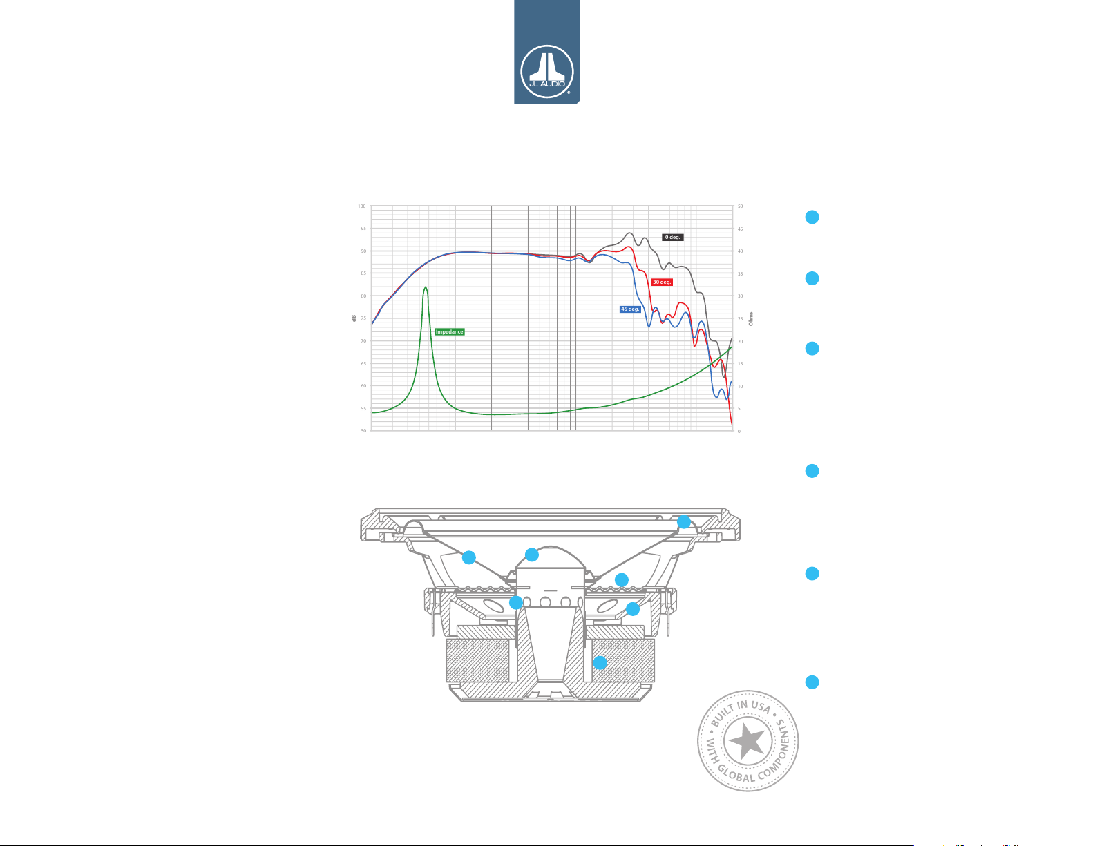
C7-650cw: 6.5-inch (165 mm) Component Woofer
0
5
10
15
20
25
30
35
40
45
50
50
55
60
65
70
75
80
85
90
95
100
OOhhmmss
ddBB
0 deg.
30 deg.
45 deg.
Impedance
INTRODUCTION
Thank you for choosing JL Audio C7 loudspeakers
for your automotive sound system. C7 is the
pinnacle of JL Audio loudspeaker design, benefitting
from patented technologies and our most advanced
development tools.
The C7-650cw is a component woofer capable
of operating in a 3-way system, with a midrange
and tweeter, or with only a tweeter in a 2-way
configuration. It has exceptional linear excursion
capability and outstanding linearity, resulting
in solid mid-bass and pure, precise mid-range
performance. Distortion and non-linearities have
been minimized through critical optimization of
dynamic motor and suspension behaviors.
We do not recommend the use of passive
crossover networks with C7 loudspeakers. Instead,
we recommend a high-quality tuning DSP and a
dedicated amplifier channel for each C7 loudspeaker
in the system. Precise setup of equalization, delay
and crossover filters will ensure optimal in-vehicle
performance.
Should you have any questions regarding the
instructions in this manual, please contact your
1
2
3
authorized JL Audio dealer for assistance, or contact
the JL Audio Technical Support Department.
INCLUDED COMPONENT & PARTS
• One (1) C7-650cw 6.50-inch (165 mm) woofer
• One (1) die-cast aluminum grille tray
• One (1) fine mesh steel grille
• One (1) spiral steel grille
• One (1) 6.35 mm female crimpable connector
• One (1) 4.7 mm female crimpable connector
• Eight (8) #8 x 1.25-inch (32 mm) sheet metal screws
2
5
6
4
3
DESIGN & TECHNOLOGIES
Cone and Dust Cap:
Vacuum-formed, mineral-filled polypropylene
1
material offers excellent damping and low mass.
The cone body features a gentle curvilinear
profile to optimize response.
A specially shaped dust cap attaches to the cone
2
body and the voice coil former to improve high
frequency behavior.
Suspension Design:
The moving assembly is suspended and
3
damped via a large-diameter, linear profile
spider formed from a Nomex®/polycotton
blend, and a positive-roll, rubber surround. The
two combine to provide optimum damping
without prematurely restricting the C7-650cw’s
outstanding excursion capability.
Motor Design:
The C7-650cw employs a high-density magnetic
4
circuit with a high-grade Y35 Strontium-ferrite
magnet, and a specially machined, T-Yoke motor
topology. Motor magnetics have been precisely
optimized utilizing advanced FEA tools to
reduce distortion and provide linear motor force
throughout the driver’s performance range.
A 32 mm (1.27 inch) diameter, overhung voice
5
coil is employed, wound with copper wire onto
a fiberglass voice coil former. The oversized
voice coil offers extended power handling
capability, minimizing thermal compression
and distortion at higher listening levels.
Chassis Design:
A purpose-engineered cast alloy basket is
6
employed, featuring thin spokes to maximize
rear open area, and our Patented Elevated
Frame Cooling technology.
Built in USA with Global Components
Page 3
C7-650cw: Specifications and Crossover Setting Guidelines
95
dB SPL
C7650cw SPECIFICATIONS
Speaker Type: Component Woofer
Nominal Diameter: 6.5 in. (165 mm)
Nominal Impedance (Znom): 4 ohms
Continuous Power Handling: 125 W
Recommended Amplifier Power: 50-175W (RMS)
Net Weight: 3.28 lbs. (1.49 kg)
Driver Rear Displacement: 0.0135 cu.ft. (0.382 liter s)
Min. Recommended Sealed Enclosure:
0.424 cu.ft. (12 liters)
Parameters:
Voice Coil Resistance (Re): 3.11 4 oh ms
Free Air Resonance (Fs): 54.5 Hz
Reference Efficiency (no): 0.304%
Efficiency: 87.0 dB @ 1W/1m | 93.0 dB @ 1W/0. 5m
Sensitivity: 90.0 dB @ 2.8 3V/1m
Electrical “Q” (Qes): 0.669
Mechanical “Q” (Qms): 6.265
Total Speake r “Q” (Qts): 0.605
Equivalent Compliance (Vas): 0.461 cu.ft. (13.05 liters)
Moving Mass (Mms): 17.67 9 g
Mechanical Compliance (Cms): 0.000482 m/N
Magnetic Strength (BL): 5.31 N /A
Effective Piston Area (Sd): 21.4 sq.in. (0.013807 sq. m)
One-Way Linear Excursion (Xmax): 5 mm
Design Bandwidth:
With 48 dB/oc tave filters: 50 Hz - 5 kHz
With 24 dB/octave f ilters: 60 Hz - 5 kHz
With 12 dB/octave filters: 70 Hz - 5 kHz
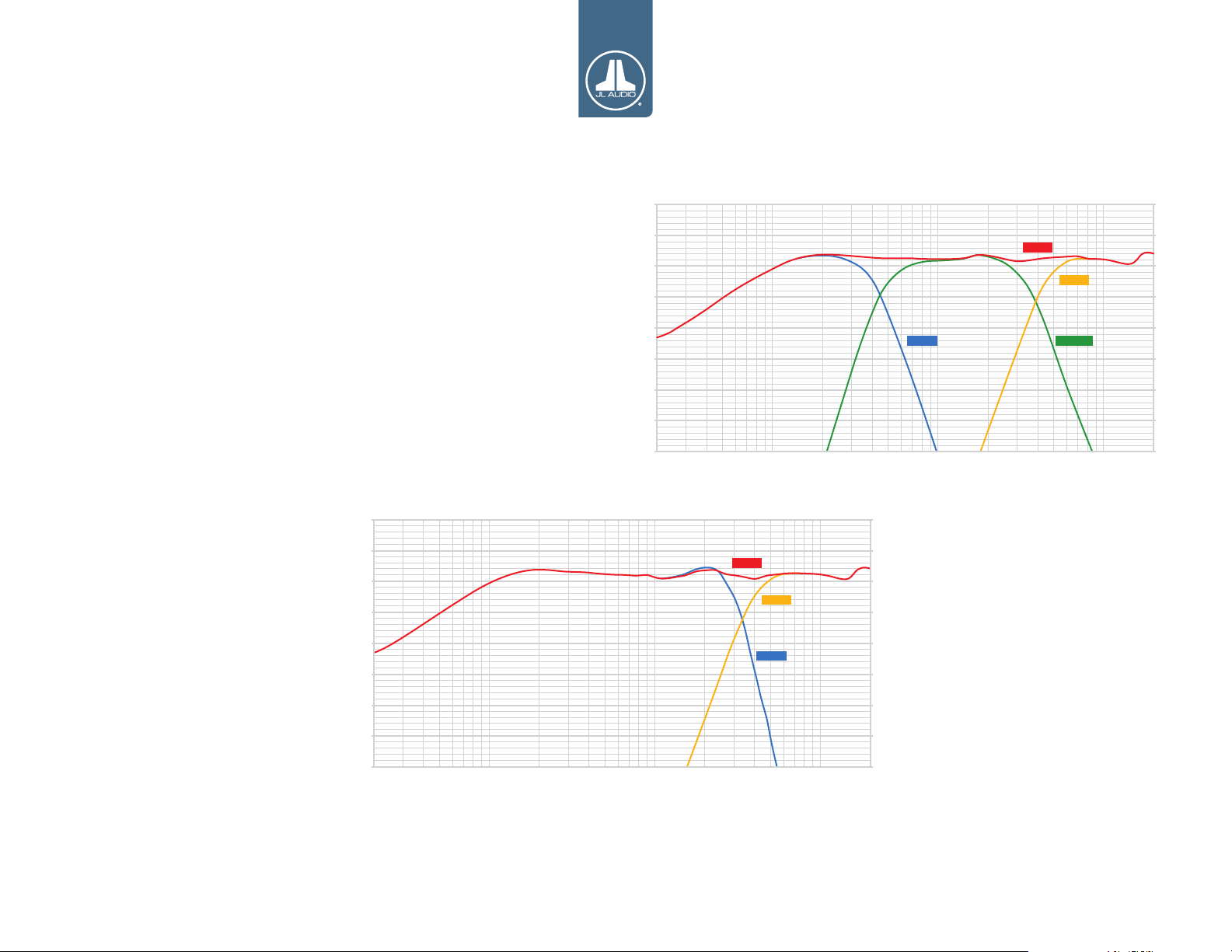
C7 3-Way Speaker System
Low-Pass: 24 dB/octave Linkwitz-Riley @ 400 Hz
High-Pass: 24 dB/octave Linkwitz-Riley @ 480 Hz
Low-Pass: 24 dB/octave Linkwitz-Riley @ 3500 Hz
High-Pass: 24 dB/octave Linkwitz-Riley @ 4500 Hz
Please note: These are recommended starting points
for tuning. In-vehicle measurements should be made to
optimize the crossover for speaker placement and vehicle acoustics.
90
85
80
75
dB SPL
70
65
60
55
C7-650cw Woofer
Level Offset: 0 dB
C7-350cm Midrange
Level Offset: 0 dB
C7-100ct Tweeter
Level Offset: -1.0 dB
95
90
85
80
75
70
65
60
55
Sum
Tweeter
C7 2-Way Speaker System
Sum
Tweeter
MidrangeWoofer
20 kHz10 kHz5 kHz1 kHz 2 kHz100 Hz50 Hz 200 Hz 500 Hz20 Hz
C7-650cw Woofer
Low-Pass: 24 dB/octave Linkwitz-Riley @ 2700 Hz
Woofer
Level Offset: 0 dB
C7-100ct Tweeter
High-Pass: 24 dB/octave Linkwitz-Riley @ 4000 Hz
Level Offset: -1.0 dB
Please note: These are recommended starting points
for tuning. In-vehicle measurements should be made to
optimize the crossover for speaker placement and vehicle acoustics.
20 kHz10 kHz5 kHz1 kHz 2 kHz100 Hz50 Hz 200 Hz 500 Hz20 Hz
3
Page 4

C7-650cw: Dimensions
7. 20 i n.
183 mm
0.98 in.
25 mm
6.12 in.
156 m m
4
5.56 in.
141 mm
6.50 in.
165 mm
3.94 in.
100 m m
2.77 in.
70 mm
Page 5

C7-650cw: Installation
CROSSOVER CONSIDERATIONS
Passive crossover networks are not included with
C7 drivers, as they are designed for active systems.
Actively configured systems allow all filtering and/or
equalization to be configured prior to reaching the
amplifier, thus avoiding the technical compromises
of passive crossover networks. The result is
linear, crystal clear audio output and minimal
distortion. For optimum performance, we strongly
recommend the use of a high-quality DSP and a
dedicated amplifier channel.
SPEAKER WIRING
If you will be using the factory speaker wires, it
may be necessary to change the terminations. This
may be accomplished by using an adaptor plug
or simply by cutting the factory connector off and
using the supplied crimp connectors to terminate
the speaker wires. The larger connector is for the
positive terminal and the smaller connector is for the
negative terminal of the C7-650cw.
If you choose to run new speaker wires, protect
all wiring from sharp edges by carefully routing
them, securing them and using grommets and loom
where appropriate. If you are running wires into a
door, use existing factory wiring boots whenever
possible. If you are drilling new holes, file their edges
and install rubber grommets into each hole. Wires
running into car doors should be covered with a
protective, flexible PVC sleeve. Make sure that the
wires will clear door hinges and other structures in
the door.
SPEAKER INSTALLATION
The speakers should be installed in one of the
following ways depending on location:
Factory Location: Your new speakers have been
designed to install, without modifications, into most
vehicles that accept a 6.50-inch (165 mm) speaker.
Most factory 6.50-inch speakers use four mounting
screws which will line up with the mounting holes
on your woofers.
It is absolutely vital that the speaker frame fits into
the mounting hole cleanly. This must be checked
prior to tightening the screws. Do not force the
frame into a hole that is too small. Do not tighten the
speaker onto an uneven mounting surface. This will
damage your speakers. The speaker should also fit so
that air does not leak around the mounting flange.
Air leaks will cause a severe degradation in sound
quality. Seal any air leaks with an automotive-grade
sealant material. Hand-tighten the screws evenly in
a criss-cross pattern to avoid bending the speaker
frame or stripping the mounting screw holes. (See
Diagram C).
Custom Location: Select a desired mounting
location with an even surface. Tightening a
speaker onto an uneven mounting surface can
damage it. Mark the center and the outline of the
speaker’s mounting hole. Before drilling or cutting
on your interior panels, use a utility knife to cut
any fabric, vinyl or leather from hole locations.
These materials can easily be snagged by a drill or
a saw, causing damage to the panel and possible
bodily injury. Drill a pilot hole in the center of the
proposed speaker mounting hole. Then, using
an appropriate cutting tool, make the circular
cut out for the speaker. File any rough edges.
After cutting the hole, check to see that
the speaker frame fits into its mounting
hole cleanly. Do not force the frame into a hole
that is too small. Once the speaker is in place, use
the holes on the speaker’s mounting flange to
mark the panel where the four mounting screws
will be positioned (See Diagram D). Remove the
speaker and drill 1/8-inch (3 mm) holes at each
mark. Connect the speaker wires, observing correct
polarity, and secure the speaker and grille tray to the
panel by evenly tightening by hand the provided #8
x 1.25 inch (32 mm) mounting screws. Make sure the
speaker is secured so that air does not leak around
the mounting flange. Air leaks will cause a severe
degradation in sound quality. Seal any air leaks with
an automotive-grade sealant material.
Finally, select your preferred grille style and
insert it into the grille tray, pressing around
its edge until seated firmly in the tray.
5
Page 6

Diagram C:
!!
Factory Location Speaker Installation
C7-650cw: Installation
Diagram D:
Custom Location Speaker Installation
WARNING
Hand-tighten the screws evenly in a
criss-cross pattern to avoid bending
the speaker frame or stripping the
mounting screw holes.
6
Page 7

C7-650cw: Installation Notes
7
Page 8

C7-650cw-MAN 012518
Limited Warranty
JL AUDIO warrants this speaker to be free of defects in materials and
workmanship for a period of one (1) year from the original date of purchase.
This warranty is not transferrable and applies only to the original purchaser
of the product from an authorized JL AUDIO dealer. Should service be necessary
under this warranty for any reason due to manufacturing defect or malfunction,
JL AUDIO will, at its discretion, repair or replace the defective product with new
or remanufactured product at no charge.
Damage caused by the following is not covered under warranty: accident,
misuse, abuse, product modification or neglect, failure to follow installation
instructions, unauthorized repair attempts, misrepresentations by the seller.
This warranty does not cover incidental or consequential damages and does not
cover the cost of removing or reinstalling the unit(s). Cosmetic damage due to
accident or normal wear and tear is not covered under warranty.
Any applicable implied warranties are limited in duration to the period of
the express warranty as provided herein beginning with the date of the original
purchase at retail, and no warranties, whether express or implied, shall apply
to this product thereafter. Some states do not allow limitations on implied
warranties, therefore these exclusions may not apply to you. This warranty gives
you specific legal rights, and you may also have other rights which vary from
state to state.
If you need service on your JL AUDIO product:
All warranty returns should be sent to JL AUDIO freight prepaid through an
authorized JL AUDIO dealer and must be accompanied by proof of purchase
(a copy of the original sales receipt). Direct returns from consumers or nonauthorized dealers will be refused unless specifically authorized by JL AUDIO
with a valid return authorization number. Warranty expiration on products
returned without proof of purchase will be determined from the manufacturing
date code. Coverage may be invalidated as this date is previous to purchase
date. Return only defective components. Non-defective items received will be
returned freight-collect. The customer is responsible for shipping charges and
insurance in sending the product to JL AUDIO. Freight damage on returns is not
covered under warranty. Always include proof of purchase (sales receipt).
For Service Information in the U.S.A. please call:
JLAudio customer service: (954) 443-1100 during
normal business hours (Eastern Time)
JLAudio, Inc
10369 North Commerce Parkway, Miramar, FL 33025
International Warranties:
Products purchased outside the United States of America are covered only by
that country’s distributor and not by JLAudio, Inc.
www.jlaudio.com
10369 North Commerce Parkway • Miramar, Florida • 33025 • USA
“How we pla y.”, “Ahead of the Curve ”, “JLAudio” and the J LAudio logo are regi stered tradem arks of JLAudio, In c.
©2017 JLAudio, Inc. • For mo re detailed in formation ple ase visit us onlin e at www.jlaudio.com. Due to our polic y of continuous pr oduct develo pment, all spe cification s are subject to cha nge without no tice.
“C7” and it s respective l ogo are trademar ks of JLAudio, Inc .
 Loading...