

JL Audio 300/4v3 Owner's Manual
OWNER’S MANUAL
300 W CLASS-A/B FOUR-CHANNEL FULL-RANGE AMPLIFIER
300/4
v3
Thank you for purchasing a JLAudio amplifier
for your automotive sound system.
Your amplifier has been designed and manufactured to exacting
standards in order to ensure years of musical enjoyment in your
vehicle. For maximum performance and extended warranty
coverage, we highly recommend that you have your new amplifier
installed by an authorized JLAudio dealer. Your authorized
dealer has the training, expertise and installation equipment
to ensure optimum performance from this product. Should you
decide to install the amplifier yourself, please take the time
to read this manual thoroughly so as to familiarize yourself
with its installation requirements and setup procedures.
If you have any questions regarding the instructions in this
manual or any aspect of your amplifier’s operation, please
contact your authorized JLAudio dealer for assistance. If you
need further assistance, please call the JLAudio Technical
Support Department at (954) 443-1100 during business hours.
2 | JL Audio - 300/4v3 Owner’s Manual
3
Cooling Efficiency Considerations:
Your JL Audio amplif ier employs an
advanced t ype of heat management, called
RealSink™. This featu re takes advantage of
convection a nd radiation effects to remove
heat from the a mplifier circuitry. For optimum
cooling performance, the ver tical heat sink s
located at the back of the amplifier should be
exposed to as large a volume of air as possible.
Enclosing t he amplifier in a sma ll, poorly
ventilated chamber can lead to excessive heat
build-up and degraded performa nce. If an
installation calls for an enclosure around the
amplif ier, we recommend that this enclosure
be ventilated with the aid of a fan. In normal
applications, fan-cooling is not necessary, but
you still need to follow some basic guidelines:
• Amplifier mounted vertically w ith heat sink fi ns
pointing up: Optimum
• Amplifier mounted horizontally,
right side up: Good
• Amplifier mounted horizontally, but upside
down: Fair (not recommended if there is
less tha n 1 inch (2.5 cm) clearance above the
amplif ier heat sinks)
• Amplifier mounted vertically w ith heat sink fi ns
pointing laterally: Fair
• Amplifier mounted vertically w ith heat sink fi ns
pointing down: Poor (not recommended)
If mounting the amplifier under a seat,
make sure t here is at least 1 inch (2.5 cm) of
space above the amplifier’s outer shell to permit
proper cooling.
Safety Considerations:
Your amplifier needs to be instal led in a dry,
well-ventilated environment and in a ma nner
which does not i nterfere wit h your vehicle’s safety
equipment (air bags , seat belt systems, AB S brake
systems, etc.). You should also ta ke the time to
securely mou nt the amplifier using appropriate
hardware so that it does not come loose in t he
event of a colli sion or a sudden jolt to the vehicle.
Stupid Mistakes to Avoid:
• Check before dril ling any holes in your
vehicle to make sure that you will not be
dril ling through a ga s tank, brake line, wiring
harness or other vital vehicle s ystem.
• Do not run system wiring outside or under neath
the vehicle. This is an extremely dangerous
practice w hich can result in severe damage to
your vehicle a nd person.
• Protect all system wires from sharp metal
edges and wear by carefully routing them,
tying them down and using grommets and
loom where appropriate.
• Do not mount t he amplifier in t he engine
compart ment, under the vehicle, on t he roof
or in any other area that will expose the
amplif ier circuitry to t he elements.
PROTEC T YOUR HE ARING!
We value you as a long-term cu stomer. For
that reason, we urge you to practice rest raint in
the operat ion of this product so as not to damage
your hearing and that of others in your vehicle.
Studies have shown that continuous exposure to
high sound pressure levels can lead to permanent
(irreparable) hearing loss. This and al l other
high-power amplifiers are capable of producing
such high sound pressure levels when con nected
to a speaker system. Please lim it your continuous
exposure to high volume levels.
While d riving, operate you r audio system in
a manner that still allows you to hear necessary
noises to operate your vehicle safely (horns,
sirens, etc.).
SERIAL NUMBER
In the event t hat your amplifier requires
service or is ever stolen, you will need to
have a record of the product’s serial number.
Please take the time to enter that nu mber in
the space prov ided below. The serial number
can be found on t he bottom panel of the
amplif ier and on the amplif ier packaging.
Serial Number:
INSTALLATION APPLICATIONS
This ampl ifier is designed for operation in
vehicles with 12V, negat ive-ground electrical
systems. Use of this product in vehicles with
positive ground and/or voltages other than 12V
may result in d amage to the product and w ill void
th e war rant y.
This produc t is not certified or approved for
use in ai rcraft.
Do not attempt to “bridge” the output s of this
amplif ier with the outputs of a second amplifier,
including an identical one.
PLANNING YOUR INSTALLATION
It is important that you take the t ime to read
this ma nual and that you plan out your
installation carefu lly. The following are some
considerations that you must take into account
when plann ing your instal lation.
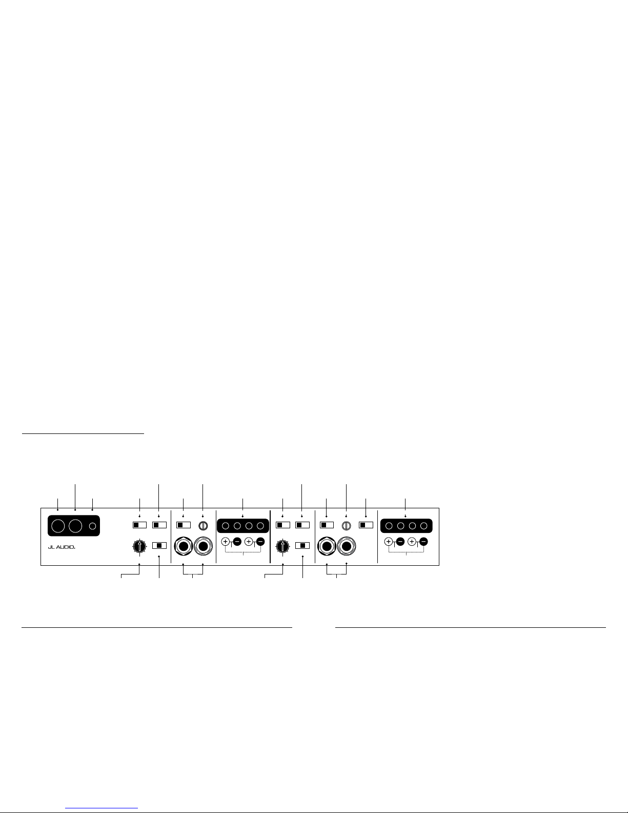
Front Channel
Input Voltage
Range Selector
(pg. 6)
Front Channel
Filter Slope
Selection
(pg. 8)
Front Channel
Filter Frequency
Range Selector
(pg. 8)
Front Channel
Left and Right
Input Jacks
(pg. 6)
Rear Channel
Left and Right
Input Jacks
(pg. 6)
Front Channel
Input Mode
Selector
(pg. 6)
Remote Turn-On
Connector
(pg. 6)
Chassis Ground
Connector
(pg. 6)
+12 V Power
Connector
(pg. 5)
Front Channel
Speaker Outputs
(pg. 8)
Rear Channel
Input Voltage
Range Selector
(pg. 6)
Rear Channel
Filter Slope
Selection
(pg. 8)
Rear Channel
Filter Frequency
Range Selector
(pg. 8)
Rear Channel
Input Sensitivity
Control
(pg. 7)
Rear Channel
Speaker Outputs
(pg. 8)
Front Channel
Filter Cuto
Frequency Selector
(pg. 8)
Front Channel
Filter Mode
Selector
(pg. 7)
Rear Channel
Filter Mode
Selector
(pg. 7)
Rear Channel
Filter Cuto
Frequency Selector
(pg. 8)
Front Channel
Input Sensitivity
Control
(pg. 7)
Bridged
Left Right
+12VDC Ground Remote Front Filter Controls Front Input Section Front Speaker Outputs
Bridged
Left Right
Rear Speaker Outputs
Left Ch. Right Ch.Filter Freq. (Hz)
Filter Slope
Freq. Range
Input Voltage Input Sens. Input Mode
12dB | 24dB
Filter Mode
Off | LP | HP
x1 | x10 Low | High
Rear Input Section
Left Ch. Right Ch.
Input Voltage Input Sens.
Low | High 2ch | 4ch
50
60
7595130
200
500
300 /4v3
Four-Channel Full-Range Amplifier
Rear Filter Controls
Filter Freq. (Hz)
Filter SlopeFreq. Range
12dB | 24dB
Filter Mode
Off | LP | HP
x1 | x10
50
60
7595130
200
500

4 | JL Audio - 300/4v3 Owner’s Manual
5
14) Make necessa ry adjustments to the i nput
sensitiv ity controls to obtain the right
overall out put and the desired balance
in the system. See Appendix C (pages 16, 17)
for the recommended input sensitivit y
setting method.
15) Enjoy the fru its of your labor with your
favorite music.
POWER CONNECTIONS
Before installing the amplifier,
disconne ct the negative (grou nd) wire
from the veh icle’s battery. Th is will prevent
accidenta l damage to the system, the vehicle
and your pers on during installation.
Bridged
Left Right
+12VDC Ground Remote
Front Filter Controls Front Input Section Front Speaker Outputs
Bridged
Left Right
Rear Speaker Outputs
Left Ch. Right Ch.Filter Freq. (Hz)
Filter Slope
Freq. Range
Input Voltage Input Sens. Input Mode
12dB | 24dB
Filter Mode
Off | LP | HP
x1 | x10 Low | High
Rear Input Section
Left Ch. Right Ch.
Input Voltage Input Sens.
Low | High 2ch | 4ch
50
60
7595130
200
500
300 /4v3
Four-Channel Full-Range Amplifier
Rear Filter Controls
Filter Freq. (Hz)
Filter SlopeFreq. Range
12dB | 24dB
Filter Mode
Off | LP | HP
x1 | x10
50
60
7595130
200
500
+12V Battery Connection
You will need to connect a power wire to
the vehicle’s posit ive battery termi nal, using an
appropriate power r ing or speciali zed battery
terminal connector, such as the JLAudio
XB-BTU or XD-BTS. This connection must
be tight and corrosion-free to ensure proper
connectivity. This wire MUST be fused
appropriately for sa fety. Any power wires run
through metal barriers (such as firewalls), must
be protected w ith a high qualit y insulating
grommet to prevent damage to the insu lation
of the wire. Failure to do so may result i n a
dangerous short circuit.
Power Wire Requirements
The 300/4v3’s “+12 V DC” and “Grou nd”
connections are designed to accept 4 AWG power
wire. 4 AWG pure copper wire is recommended
for any power wire run longer than 72 inches (180
cm). For runs shorter than 72 inches, 8 AWG pure
copper power wi re is acceptable.
If you are installing the 3 00/4v3 with other
amplif iers and wish to use a single main power
wire, us e 2 AWG or 1/0 AWG pure copper
wire as a ma in power wire. This 2 AWG or
1/0 AWG power wire shou ld terminate into a
fused d istribution block mounted as close to
the ampli fiers as possible and shou ld connect to
the 300/4v3 wit h 4 AWG or 8 AWG pure copper
power wi re.
Please note that lower AWG numbers mean
bigger wire and vice-versa (1/0 AWG is the largest,
2 AWG is smal ler, then 4 AWG, then 8 AWG, etc.).
IMPORTANT
!
We do not recommend the use of “copperclad aluminum wire” or “CCA” wire because
this wi re is significant ly less conductive than
pure copper wi re. Only use pure copper power
wire, such a s JLAudio’s Premium Power Wire.
Tinned copper w ire (silver color) is acceptable as
the tin-plating is only a very minor c omponent
of the wire.
Fuse Requirements
The installation of a fuse on t he main
power wire, w ithin 18 wire inches (45 cm)
of the positive battery terminal is vital to
protect the w ire and the vehicle from f ire in
the event of a collision or short-circuit . The
fuse va lue at each power wire should be just
high enoug h for all of the equipment bei ng run
from that p ower wire. Do not use a fuse wit h
a value that far exceeds the tota l fuse rating
of the elect ronics connected to the wire.
If only the 300/4v3 is being run from t hat
power wire, we recommend a 40A fuse be
used. AGU (big glass fuse) or MaxiFuse™ (big
plastic-body fuse) types are recommended.
If other amplifiers are also being powered from
a main power w ire and exceed 80 amps in total
fuse rat ing, we recommend the use of an ANL
(large-bl ade) fuse and holder at the battery plus
a fused d istribution block nea r the amplifiers.
Each amplifier must be fused independently at the
outputs of the f used power distribut ion block. We
recommend appropriately rated MaxiFuse™ fuses
and a JLAudio fused distribution block.
Please consu lt with your JLAudio
dealer to ma ke sure that the wire, fuse
holder and fuse ratings are appropriate for
your system’s needs . The safety of your
installation depends on appropriate power
connections and fuse protect ion.
PRODUCT DESCRIPTION
The JLAudio 300/4v3 is a four-channel fu ll-
range ampl ifier utili zing patented Absolute
Symmetry™ Class A/B technology for all
channels. All channels benefit from JLAudio’s
exclusive R.I.P. S. power supply design which
optimi zes the output of each channel pair for any
impedance between 1.5 and 4 ohms p er channel.
The 300/4v3 can be operated in the
following modes:
1) As a full-system amplifier i n bi-amp mode with
one pair of cha nnels driving subwoofers in lowpass mode (75W x 2 or 150W x 1) and the other
pair of cha nnels driving ma in speakers in highpass mode (75W x 2).
2) As a four-channel satellite amplifier in a
bi-amplified system, delivering high-passed
signals to front and rear speaker systems.
The 300/4v3’s flexible input and crossover
sections permit operation wit h a wide variety
of source units and system configurations. The
300/4v3 can oper ate with a single pair of stereo
inputs or wit h separate inputs for front a nd rear
channels, if the source unit i s equipped with front
and rear outputs.
TYPICAL INSTALLATION SEQUENCE
The followi ng represents the sequence for
a typical amplifier installation, using an
after market source unit or OEM Interface
processor (like the CleanSweep® CL441dsp).
Additiona l steps and different procedures may
be required in some applications. If you have
any questions, please contact you r authorized
JL Audio dealer for assistance.
1) Disconnec t the negative batter y post
connection and secure the disconnected cable
to prevent accidental re-connection during
installation. This step is not optional!
2) Run power wire from the battery loc ation
to the amplifier mounting location, taking
care to route it in such a way that it will
not be damaged and will not inter fere with
vehicle operat ion. 4 AWG is recom mended
for wire ru ns greater than 72 inches (180
cm) in length. Use of 8 AWG power wire is
acceptable for shorter runs, such as from a
power distribution block to the amplifier or
from a tru nk-mounted battery. Use a 2 AWG
or 1/0 AWG main power w ire with a fused
power distribution block when additional
amplif iers are being insta lled with the 30 0/4v3
and powered from the same main power wire.
3) Connect power w ire to the positive battery
post. Fuse t he wire with an appropr iate fuse
block (and connectors) withi n 18 inches (45
cm) wire length of the positive battery post.
This fuse is essential to protect the vehicle.
Do not install the fuse until the power wire
has been connected to the amplifier.
4) Run signa l cables (RCA cables) and remote
turn-on w ire from the source un it or interface
processor to t he amplifier mounting location.
5) Run speaker wire from the speaker systems to
the ampli fier mounting locat ion.
6) Find a good, solid, bare metal grounding
point close to t he amplifier and connect the
negative power w ire to it using appropriate
hardware. Use mini mum 8 AWG power wire,
no longer than 36 inches (90 cm) or 4 AWG
wire up to 60 i nches (150 cm) long from the
amplif ier to the ground connection point. In
some vehicles, it may be necessary to upgrade
the batter y’s ground wire as well. (See page 6
for importa nt notice).
7) Securely mount the amplifier using
appropriate hardware.
8) Connect the remote turn-on wire a nd the
positive and negative power wires to the
amplif ier’s power connector plug. Then insert
the power connector plug into the amplifier’s
power connector receptacle, pushing firmly.
9) Connect t he RCA input cables
to the amplifier.
10) Connect the speaker wires to the speaker
connector plugs and insert the plugs f irmly
into the speaker connector receptacles.
11) Carefully review the amplif ier’s control
setti ngs to make sure that t hey are set
according to the needs of the system.
12) Instal l power wire fuse (40A for a
single 30 0/4v3) and re connect the negative
battery post terminal.
13) Turn on the source unit at a low level
to double-check that the amplif ier is
config ured correctly. Resist t he temptation
to crank it up until you have verified the
control settings.

6 | JL Audio - 300/4v3 Owner’s Manual
7
on each “Input Voltage” switch selects an
input sensitivity range between 800mV and 8V.
This is useful for certain high-output preamp
level signa ls as well as speaker-level output
from source u nits and small ampl ifiers. To use
speaker-level sources, splice the speaker output
wires of t he source unit or smal l amplifier
onto a pair of RCA plugs for each input pair
or use the JL Audio ECS Speaker Wire to RCA
adaptor (XD-CLRAIC2-SW).
IMPORTANT
!
The output of the ampl ifier will decrease
for a given input voltage when the “Input
Range” sw itch is placed in the “High”
position. Conversely, the output will be hig her
with the switch in the “Low” posit ion. While
this may sound counter-intuitive, it is correct
as described.
3) Input Sensitiv ity Adjustment: Located next
to the “Input Voltage” s witch in each input
section i s a rotary control lab eled “Input
Sens.”. Once the appropr iate “Input Voltage”
range has been selected, this control can be
used to match t he source unit’s output voltage
to the input stage of each pair of amplifier
channels for maximum clean output. Rotating
the control clo ckwise wil l result in higher
sensitiv ity (louder for a given input volta ge).
Rotating t he control counter-clockw ise will
result in lower sensitivity (quieter for a given
input voltage). To properly set each pair
of amplif ier channels for max imum clean
output, please refer to Appendix A (page 14)
in this manual. After u sing this procedure,
you can then adjust the relative level of each
channel pa ir by adjusting the input sensitivity
downward on eit her or both channel pairs, if
they require attenuation to achieve the desired
system ba lance. Do not increa se the “Input
Sens.” setting for any a mplifier in the system
beyond the ma ximum level establ ished during
the procedure outlined in Appendix A (page
14). Doing so will result in audible distortion
and possible speaker damage. Be aware that
both “Input Sens.” adjustments wil l have to
be made, rega rdless of how many input cables
are feedi ng the amplifier. These controls will
allow you to set the appropriate relative levels
for front and rear channels and any ot her
amplif ier channels in the system.
CROSSOVER CONTROLS
Crossovers are groups of individual electronic
filters which allow only cer tain frequency
ranges to pa ss through them by at tenuating
frequencies outside the selected ra nge. These
filters allow the user to spec ify what frequenc y
range wi ll be sent out of each channel section
of the ampli fier. This, in turn, allows each
speaker s ystem to only reproduce a range of
frequencies it is well-suited for, resulti ng in
reduced distortion and improved fidelity.
Front And Rear Filter Section:
Bridged
Left Right
Front Filter Controls
Front Input Section Front Speaker Outputs
Left Ch. Right Ch.
Filter Freq. (Hz)
Filter Slope
Freq. Range
Input Voltage Input Sens. Input Mode
12dB | 24dB
Filter Mode
Off | LP | HP
x1 | x10
Low | High
|
4ch
50
60
7595130
200
500
Bridged
Left Right
Bridged
Left Right
Rear Speaker Outputs
Left Ch. Right Ch.Filter Freq. (Hz)
Filter Slope
Freq. Range
Input Voltage Input Sens. Input Mode
12dB | 24dB
Filter Mode
Off | LP | HP
x1 | x10 Low | High
Rear Input Section
Left Ch. Right Ch.
Input Voltage Input Sens.
Low | High 2ch | 4ch
50
60
7595130
200
500
Rear Filter Controls
Filter Freq. (Hz)
Filter SlopeFreq. Range
12dB | 24dB
Filter Mode
Off | LP | HP
x1 | x10
50
60
7595130
200
500
The 300/4v3 employs two separate, but
identical filter sections for it s front and rear
channel pa irs. These sect ions consist of the
following controls
1) “ Filter Mode” Control: This switch allows you
to config ure the filter into one of t wo filter
type s or to defeat it completely:
“Off”: Defeats the filter for that channel
section completely, allowing the f ull range of
frequencies present at the inputs to feed that
pair of cha nnels. This is useful for systems
utili zing outboard crossovers or requiring full-
range reproduc tion from that pair of channels.
“LP” (Low-Pass): Conf igures the fi lter to
attenuate frequencies above the selec ted
filter f requency. Useful for connection of
subwoofer(s) to that channel section.
“HP” (High-Pass): Configures t he filter to
attenuate frequencies below the selected
filter f requency. Useful for connection
of component speakers to that channel
section i n a bi-amplified system.
Ground Connection
The chassis ground connection must be made
using 4 AWG pure copper wire a nd should be
kept as short a s possible, while acce ssing a solid
piece of sheet met al in the vehicle. The surface of
the sheet metal should be sanded at t he contact
point to create a clean, metal-to-meta l connection
between t he chassis and the termination of
the ground wire with a brass or copper power
ring. For optima l grounding, we recommend
the use of a JL Audio ECS master ground
lug (XB-MGLU). Alternatively, a sheet met al
screw or bolt ca n be used with a sta r washer.
IMPORTANT
!
Many vehicle s employ small (10 AWG - 6
AWG) wire to grou nd the battery to the vehic le
chassis a nd to connect the alternator ’s p ositive
connection to the battery. To prevent voltage
drops, the se wires should be upgr aded to 4
AWG pure copper wire when inst alling amplif ier
systems wit h main fuse ratings above 60A.
TURN ON LEAD
The 300/4v3 uses a conventional +12V remote
turn-on le ad, typical ly controlled by the source
unit’s remote tu rn-on output. The ampli fier will
turn on when +12V is present at its “Remote”
input and turn off when +12V is switched off. If
a source unit does not have a dedicated remote
turn-on out put, the amplifier’s t urn-on lead can
be connected to +12V via a switch that derives
power from an ig nition-switched circ uit.
The 300/4v3’s “Remote” turn-on connector is
designed to accept 18 AWG – 8 AWG wire.
12 AWG is more than adequate for this purpose.
To connect the remote turn-on wire to the
amplif ier, first back out the set screw on the top
of the ampli fier, using the supplied hex wrench.
Strip 1/2 inch (12mm) of wi re and insert the
bare wire into the receptacle on the front panel
of the ampli fier, seating it fir mly so that no bare
wire is ex posed. When using smaller wire, it may
be necessa ry to strip 1 inch of insulation from
the wire and fold the bare wire in half prior to
insert ion. While holding t he wire in the termi nal,
tighten t he set screw firm ly, taki ng care not to
strip the head of the screw and making sure that
the wire is firmly gripped by the set screw.
FRONT AND REAR INP UT SECTIONS
The 300/4v3 has t wo separate input sections,
one for its front channels and another for its re ar
channels. Each section conta ins a pair of RCA-
type input jacks, an “Input Voltage” switch and
an “Input Sens.” rotar y control.
Bridged
Left Right
Front Input Section
Front Speaker Outputs
Left Ch. Right Ch.
Input Voltage Input Sens. Input Mode
Low | High
2ch | 4ch
Bridged
Left Right
Bridged
Left Right
Rear Speaker Outputs
Left Ch. Right Ch.Filter Freq. (Hz)
Filter Slope
Freq. Range
Input Voltage Input Sens. Input Mode
12dB | 24dB
Filter Mode
Off | LP | HP
x1 | x10 Low | High
Rear Input Section
Left Ch. Right Ch.
Input Voltage Input Sens.
Low | High
2ch | 4ch
50
60
7595130
200
500
The “Front Input Sec tion” also contains an
“Input Mode” switch to allow operation of a ll
four amplifier channels with one or two pairs of
input signa ls.
1) Input Mode Switch: If you w ish to operate
all four channels of the 300/4v3 wit h a single
pair of stereo inputs, select the “2ch” position
on the “Input Mode” switch and connect a
single pair of input cables to the input jacks
in the “Front Input Section”. In this mode,
the ampli fier will route the signals connected
to the front input s to the rear inputs as well.
If you wish to use separate inputs for the front
and rear channel sections (to allow front-torear fadi ng, for example) and the source u nit
is equipped w ith front and rear outputs, select
“4ch” on the “Input Mode” switch. In this
mode, you must connect separate pai rs of input
cables to each input section.
2) Input Voltage Range: A wide range of signal
input voltages c an be accommodated by each
of the 300/4v3’s input sect ions (200mV – 8V).
This wide range is split up into two subranges, accessible via switches located in each
input section of the amplifier. Be awa re that
each input section’s “Input Voltage” sw itch
will have to be configured , regardless of how
many input cables are actually feeding the
amplif ier. The “Low” position on each “Input
Vol tag e” switch selects an input sensit ivity
range bet ween 200mV and 2V. T his means that
the “Input Sens.” rotar y control will oper ate
withi n that voltage window. If you are using
an aftermarket source un it, with conventional
preamp-level out puts, this is most li kely the
position that you will use. The “High” position
 Loading...