

Page 1
INSTALLATION
INSTRUCTIONS
517-278-1226 • [email protected] • www.jksmfg.com
491 W. Gareld Avenue, Coldwater, MI 49036
Product: Steering Brace System™
Part Number: JKSOGS960 - JKSOGS962
Applications: Jeep® Cherokee XJ, 1984-01
Welcome
CONGRATULATIONS on purchasing a new Steering
Brace System from JKS Manufacturing. We are committed
to providing you with the best products available and your
satisfaction is our rst priority.
READ INSTRUCTIONS THOROUGHLY to familiarize
yourself with the required skills and tools BEFORE attempting installation.
Important
INSTALLATION REQUIRES WELDING to the unibody
chassis by a qualied welder or metal fabricator. A
bolt-on installation is not possible for this product.
CHECK STEERING GEAR TORQUE SPECS on a regular basis.
Tools Required
Metric/Standard Socket Wrench Set
Torque Wrench
Die Grinder with Sanding/Grinding Wheels
(or similar tool for cleaning chassis)
5/8” Drill Bit, or preferably a Uni-bit
(for enlarging holes in chassis)
Carbide Cutting Tool *
(for enlarging holes in chassis)
3/4” Drill Bit (for new tow hook holes)
C-clamp or Locking Pliers
Hammer *
Factory Service Manual (recommended)
Welding Equipment
Satin Black Spray Paint
* Asterisk denotes tools that are not required for some applica-
tions. Thoroughly read instructions rst to determine which tools
will be required for your application.
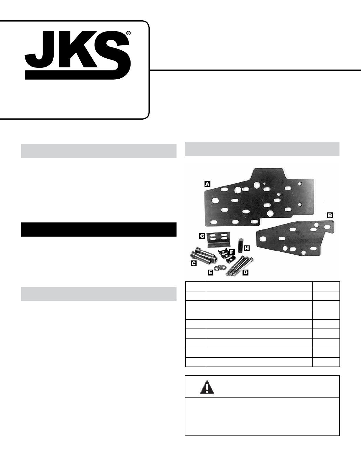
Parts
Description QTY
A
Outer Chassis Plate (3/16”) 1
B
Inner Chassis Plate (1/8”) 1
C
Support Sleeves 3
D
Steering Gear Mounting Bolts 3
E
Flat Washers 3
F
Installation Spacers 3
G
Tow Hook Support Bracket 1
H
3/4” Solid Rod 1
ATTENTION INSTALLER
Review front bumper re-installation
section on page 5 BEFORE installing
product.
JKSOGS960 /JKSOGS962JKS Steering Brace System Installation
Page 1
Page 2
ATTENTION INSTALLER
IMPORTANT NOTE REGARDING
DUAL STEERING BRACE SYSTEM
The following instructions refer to installation of a
single Steering Brace System (PN OGS960) on the
driver-side chassis rail only. For a dual Steering Brace
System (PN OGS962), the additional parts should be
installed on the passenger-side chassis rail using the
same procedures.
NOTE: Some vehicles are factory equipped with
steering gear mounting holes on both chassis rails.
Otherwise, it will be necessary to drill new holes on
the passenger-side chassis rail to accommodate the
supplied Support Sleeves.
Installation
1. PREPARE DRIVER-SIDE CHASSIS RAIL
Z The following items must be removed from the
chassis rail, along with any other components that
prevent the Chassis Plates (A & B) from tting
ush against mounting surface. Refer to factory
service manual for specic instructions.
 Tow Hook & Bracket
 Lower Radiator Support Bracket
 Front Swaybar
 Front Bumper & Bracket
Z Unbolt the steering gear and adapter plate from
the chassis. Temporarily secure the steering gear
out of the way – it should not be necessary to
disconnect uid lines or steering shaft. Discard
steering gear adapter plate.
Z Test t the Inner and Outer Chassis Plates (A & B)
to the chassis rail. Mark an outline of each plate
onto chassis surface.
Z Completely remove all paint/primer, weld slag/
spatter, or other debris from chassis surface
(inboard and outboard side) until bare metal is
exposed.
HI N T: A die grinder with sanding wheel, disc
sander, or similar tool is useful for cleaning chas-
sis surface.
Z Test t the Inner and Outer Chassis Plates (A &
B) again to check for ush tment against chassis
surface, and to ensure all debris has been removed from the necessary areas.
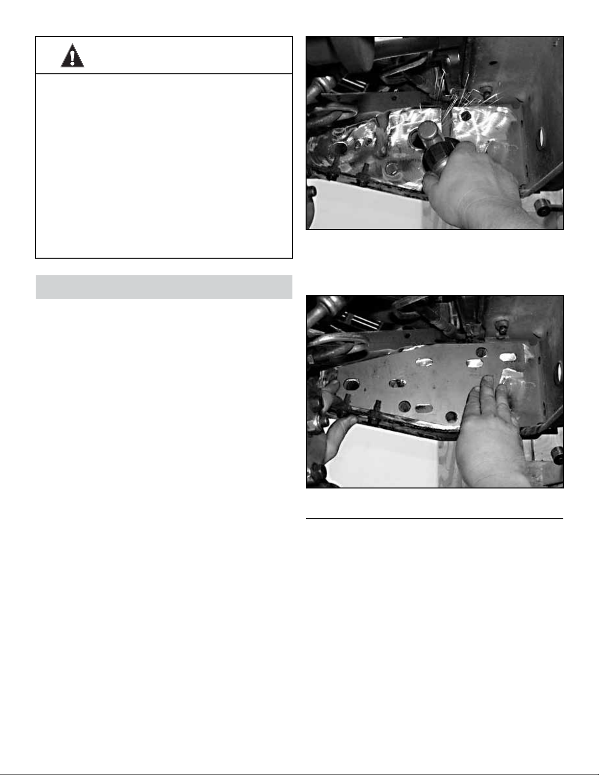
2. ENLARGE STEERING GEAR MOUNTING
HOLES IN CHASSIS
Z Locate the three (3) steering gear mounting holes
on the inboard and outboard side of chassis rail.
Z Enlarge the inboard and outboard mounting holes
to approximately 5/8” – or until narrow end of Support Sleeves (C) can be inserted.
HI N T: A uni-bit (step-drill bit) is useful for enlarging
holes to 5/8” – and more effective on the unibody
chassis than standard drill bits. A pneumatic die
grinder or dremel tool with carbide cutting attachment (shown) is also effective, particularly where
clearance is limited.
2 Page
JKSOGS960 /JKSOGS962
JKS Steering Brace System Installation
Page 3
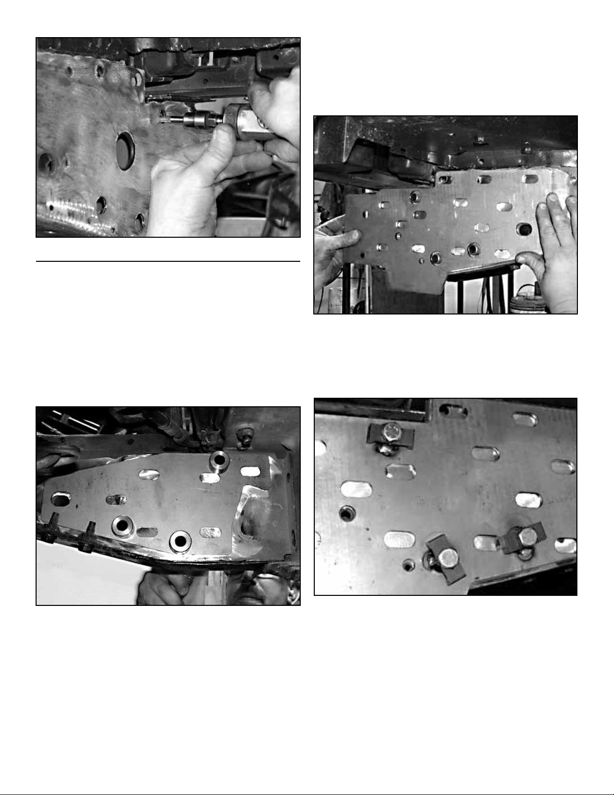
3. WELD SUPPORT SLEEVES & CHASSIS
PLATES TO FRAME
Z Position Inner Chassis Plate (B) against inboard
side of chassis.
Z Insert Support Sleeves (C) into steering gear
mounting holes from inboard side of chassis. Once
inserted, shoulder of Support Sleeves will hold
Inner Chassis Plate (B) in place. HIN T: A hammer
may be needed to tap Support Sleeves into mounting holes.
Z Position and align the Outer Chassis Plate (A)
against the outboard side of chassis. HI N T: Sup-
port Sleeves (C) should protrude through large
holes in Outer Chassis Plate (A), but need not
be in perfect alignment as any voids surrounding
holes will be lled when welded.
Z Place the supplied Installation Spacers (F) on the
Steering Gear Mounting Bolts (D) and temporarily insert bolts into Support Sleeves (C) from the
outboard side of chassis. H I N T: Recessed side of
Installation Spacer (F) should face Outer Chassis
Plate (A).
Z Insert the 3/4” Solid Rod (H) into large hole in
chassis rail. Refer to Hole Identication Diagram
on page 1 for assistance. H IN T: The 3/4” Solid
Rod lls a factory tow hook support bracket hole
and ties the Inner and Outer Chassis Plates to-
gether during the welding portion of installation.
JKSOGS960 /JKSOGS962JKS Steering Brace System Installation
Z Position steering gear against the inboard side of
chassis and align with mounting holes.
Z Thread Steering Gear Mounting Bolts (D) into
steering gear and lightly snug bolts. Make sure
both Chassis Plates (A & B) remain aligned and
ush with chassis surface.
Page 3
Page 4
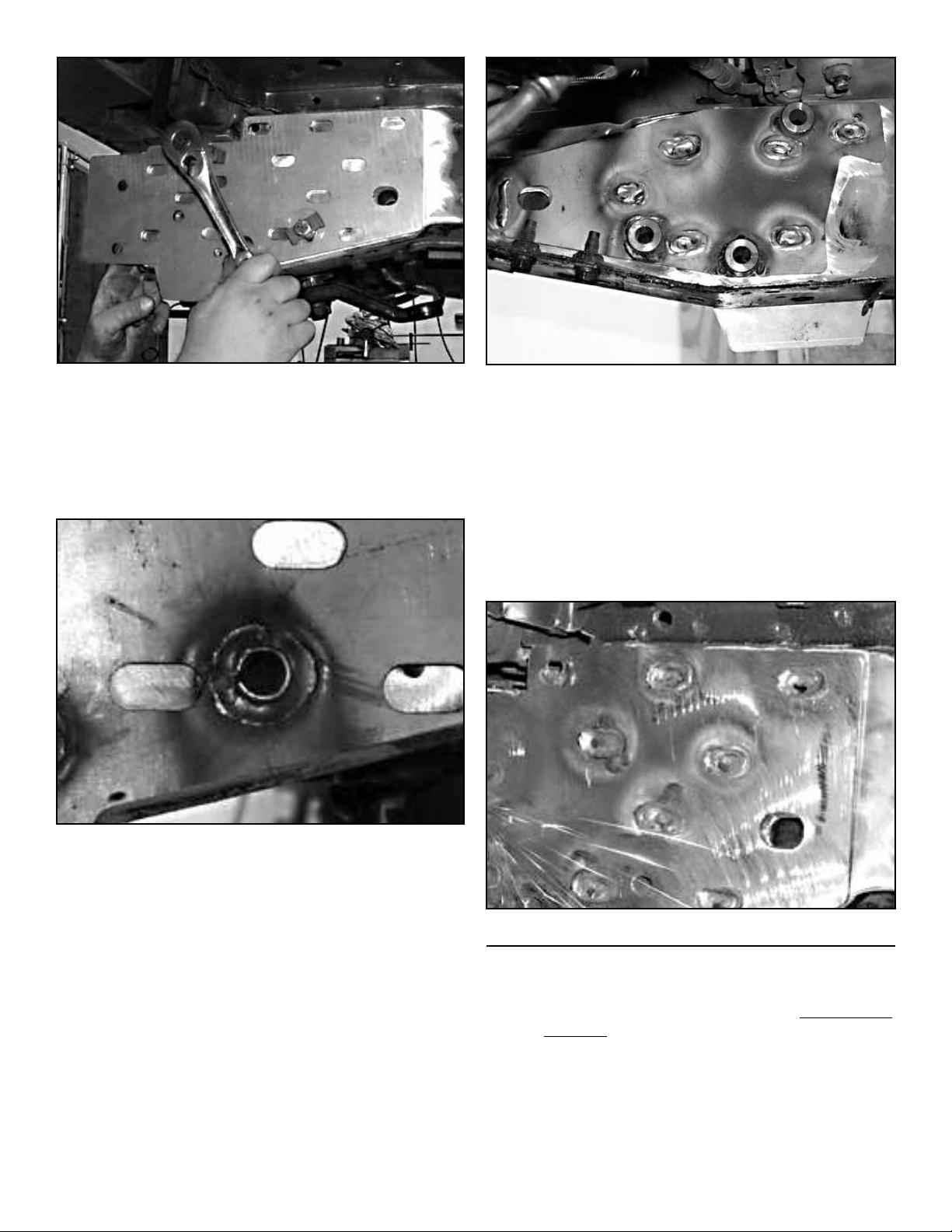
Z Tack-weld all three (3) Support Sleeves (C) to the
Outer Chassis Plate (A).
Z Working with one mounting hole at a time, remove
a Steering Gear Mounting Bolt (D) and nish welding the Support Sleeve (C) to the Outer Chassis
Plate (A), making sure any voids are completely
lled.
Z Rosette weld the 3/4" Solid Rod (H) to Inner and
Outer Chassis Plates (A & B).
Z Once welding is complete, grind any protruding
portion of the Support Sleeves (C) on outboard
side of chassis until completely ush with Outer
Chassis Plate (A).
Z Remove any other protrusions from surface of In-
ner and Outer Chassis Plates (A & B) until smooth
and completely at. H INT: A power sanding/grinding wheel or similar tool is useful for smoothing
chassis.
Z After Support Sleeves (C) have been welded to the
Outer Chassis Plate (A), secure the steering gear
out of the way to gain access to the Inner Chassis
Plate (B).
Z Weld the shoulder of all three (3) Support Sleeves
(C) to the Inner Chassis Plate (B).
Z Rosette weld Inner and Outer Plates (A & B) to
chassis at each slotted hole. Although not necessary, Chassis Plates may also be stitch-welded
along edges for additional support. H IN T: For
cleanest appearance, slotted holes can be lled
completely and sanded smooth.
4 Page
4. MOUNT TOW HOOK BRACKET
Z Position the Tow Hook Support Bracket (G) against
JKSOGS960 /JKSOGS962
the underside of chassis rail with the slotted holes
facing up. Clamp the non-slotted side of bracket to
the Outer Chassis Plate (A).
JKS Steering Brace System Installation
Page 5
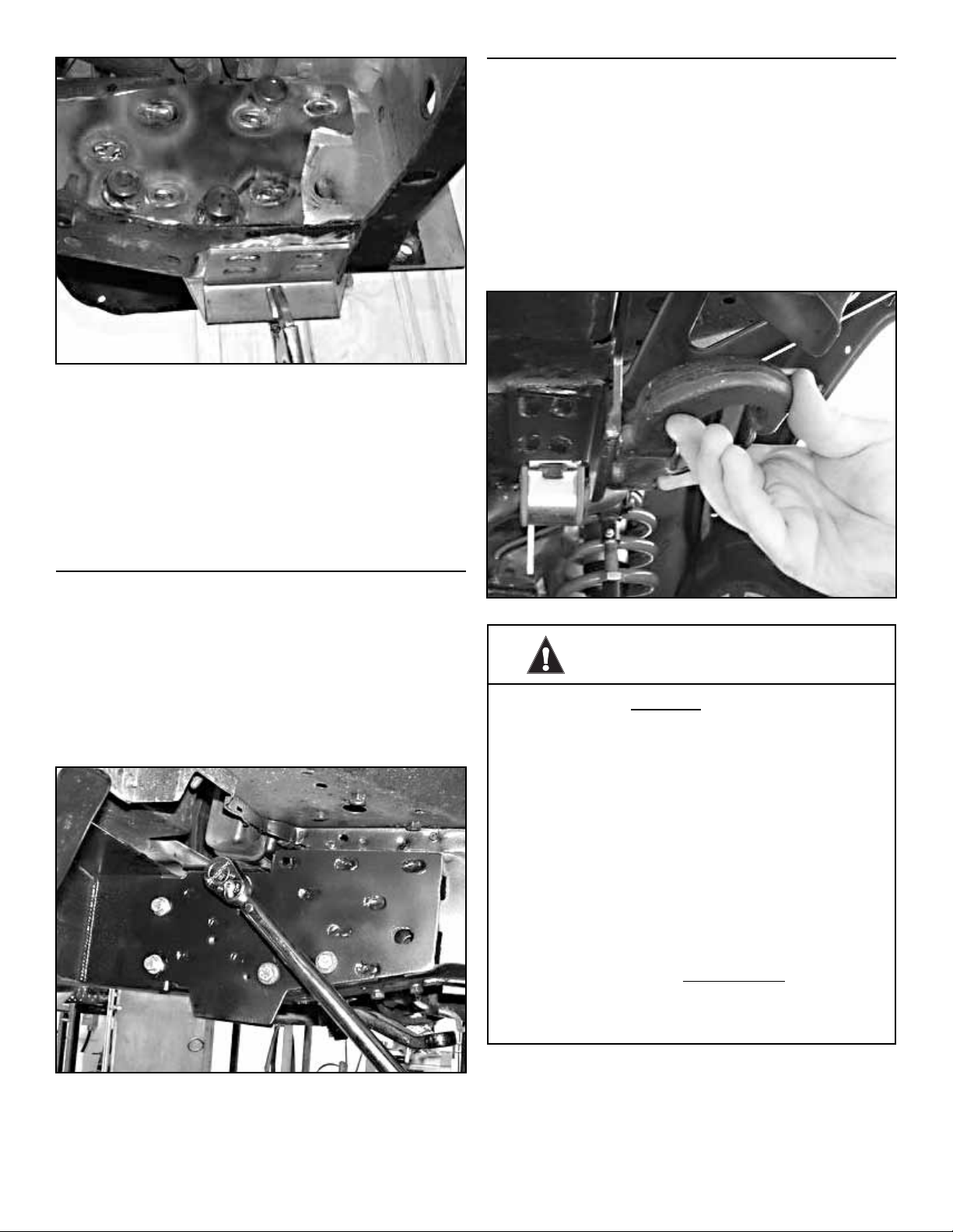
Z Weld edges and bottom seam of Tow Hook Sup-
port Bracket (G) to Outer Chassis Plate (A).
Z Rosette weld slotted holes of Tow Hook Support
Bracket (G) to underside of chassis rail.
Z Once all welding and nal sanding/grinding is com-
plete, any bare metal must be painted to prevent
corrosion. There should be no exposed metal visible when painted properly.
6. RE-INSTALL RELATED COMPONENTS
Z Re-install radiator support bracket to original
mounting location. Enlarge the upper mounting
holes of support bracket if they don’t line up.
Z Re-install front swaybar to original location.
Z Install original tow hook on vertical surface of Tow
Hook Support Bracket (G) where welded to the
Outer Chassis Plate (A). Drill new mounting holes
using a 3/4” drill bit and install tow hook using
original mounting hardware.
5. MOUNT STEERING GEAR TO CHASSIS
Z Place a Flat Washer (E) on each Steering Gear
Mounting Bolt (D) and insert bolts into Support
Sleeves (C) from the outboard side of chassis.
Z Position steering gear against the inboard side of
chassis and align with mounting holes.
Z Thread bolts into steering gear and tighten to 55-
60 ft-lb. using a torque wrench.
ATTENTION INSTALLER
READ BEFORE INSTALLING
Additional modications may be necessary
to re-install the front bumper to the reinforced
chassis. Once installed, the Chassis Plates
(A & B) increase the overall width of the
chassis rail, which may prevent the bumper
mounting brackets from tting as intended.
Z Review each of the following options BEFORE
determining the best conguration for your application.
Z TRIAL FIT the parts to familiarize yourself with any
installation complications.
Z OPTION 3 requires pre-installation modications
to the Outer Chassis Plate, and is only suggested
if OPTIONS 1 & 2 are not possible.
JKSOGS960 /JKSOGS962JKS Steering Brace System Installation
Page 5
Page 6
7. INSTALL FRONT BUMPER
The following steps are general tment suggestions only.
The actual installation procedure will depend on the
bumper-to-chassis mounting conguration.
Fabrication is required for most applications, and should
only be performed by a qualied metal fabricator or welder.
When installed correctly, the front bumper will be SECURELY attached to the Outer Chassis Plate so that any
winch loading is transferred to the chassis rails and large
tubular support member that spans them.
OPTION 1
Bolt-On Mounting Bracket
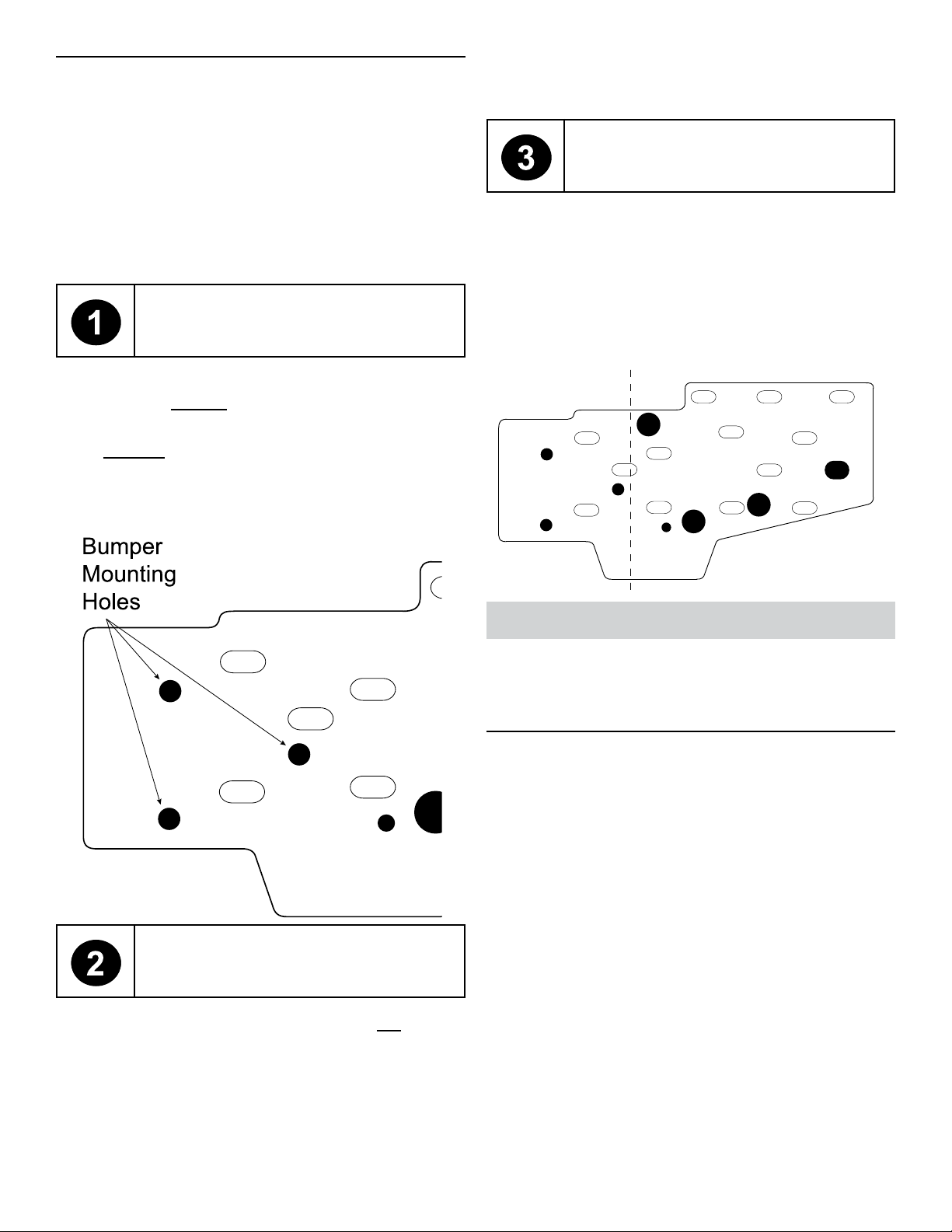
bumper mounting holes located at the front of the chassis plate. If necessary, re-drill any mounting holes or trim
Chassis Plate to t.
OPTION 1
Bolt-On Mounting Bracket
Choose this option if modication of bumper mounting
bracket is not possible, or ineffective.
Before installing Outer Chassis Plate (A), cut in half as
indicated in the illustration and discard the front portion.
Install the rear portion of chassis plate as instructed. Mount
bumper to original mounting holes in chassis. If necessary,
re-drill any mounting holes or trim Chassis Plate to t.
Choose this option if the front bumper will t the reinforced chassis without interference.
Install the front bumper with the mounting bracket positioned outboard of the Outer Chassis Plate (A). Use the
new bumper mounting holes located at the front of the
chassis plate – see illustration below. If necessary, re-drill
any mounting holes or trim Chassis Plate to t.
Cut
Line
Front Portion Rear Portion
Maintenance
Check Steering Gear Mounting Bolt (D) torque specications regularly.
©2013 JKS Manufacturing, Inc & Aftermarketing, LLC
Revision Date 11/1/2013
OPTION 2
Modify Bumber Bracket
Choose this option if the front bumper will not t the
reinforced chassis.
Modify the bumper mounting bracket to accommodate the
additional 3/16” thickness of the Outer Chassis Plate (A).
Install the front bumper with the mounting bracket positioned outboard of the Outer Chassis Plate. Use the new
6 Page
JKSOGS960 /JKSOGS962
JKS Steering Brace System Installation
 Loading...