

Page 1
INSTALLATION
INSTRUCTIONS
517-278-1226 • [email protected] • www.jksmfg.com
491 W. Gareld Avenue, Coldwater, MI 49036
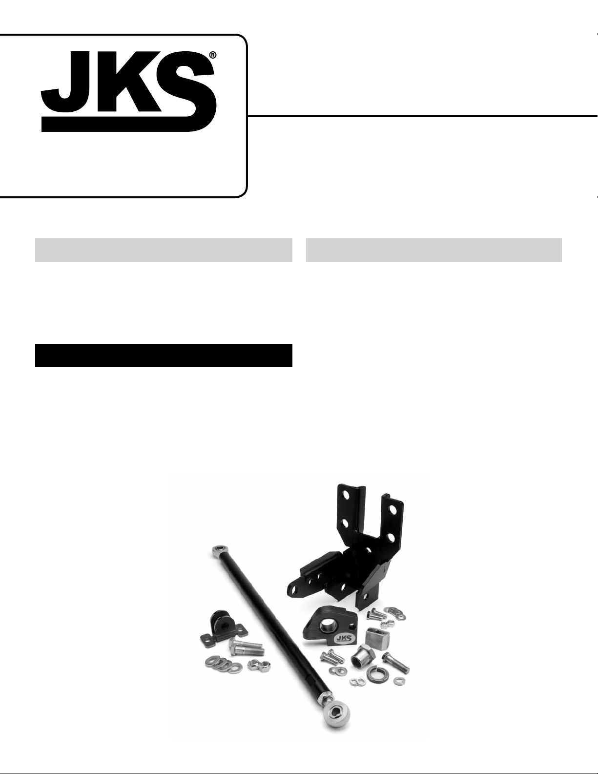
Product: Front Trackbar + Sector Shaft Reinforcement Kit
Part Number: JKSOGS166
Applications: Wrangler JK, 2007+
Welcome
CONGRATULATIONS on purchasing the Front
Trackbar + Steering Sector Shaft Reinforcement Kit
from JKS Manufacturing. We are committed to providing you with the best products available and your
satisfaction is our rst priority.
Important
INSTALLATION REQUIRES WELDING by a quali-
ed welder or metal fabricator. A bolt-on installation is not possible for this product.
INSTALLATION REQUIRES OE type steering box.
NOT COMPATIBLE WITH TeraFlex track bars.
NOT COMPATIBLE WITH frame-mounted track bar
drop brackets.
Tools Required
Hydraulic Floor Jack & Jack Stands
Metric/Standard Socket Wrench Set
Torque Wrench
15/16” Open End Wrench
Black Marker or Metal Scribe
Flat Black Spray Paint
Anti-Seize Lubricant
Compact Die Grinder with Sanding Wheel (or
equivalent tool for removing paint from chassis)
Welding Equipment
Assortment of Small Pry Bars *
Factory Service Manual (recommended)
* Asterisk denotes tools that are not required for some applica-
tions. Thoroughly read instructions rst to determine which tools
will be required for your application.
JKSOGS16 6JKS Front Trackbar + Sector Shaft Reinforcement Installation
Page 1
Page 2
Parts
Description Part # QTY
A
Trackbar Chassis Bracket 03038 1
B
7/16” x 1” GR5 Bolt 13155 2
C
7/16” Flat Washer 33084 4
D
7/16” Locking Nut 37266 2
E
Steering Sector Pillow Block 03041 1
F
Spherical Bearing 165100 1
G
Sector Bearing Nut 03042 1
H
7/8” Split Washer 33899 1
I
Pillow Block Frame Mount 03043 1
J
7/16” x 1-3/4” GR8 Bolt 18877 1
K
7/16” Split Washer 33624 1
L
3/8” x 1” GR5 Bolt 13105 2
FRONT TRACKBAR + SECTOR SHAFT
REINFORCEMENT KIT
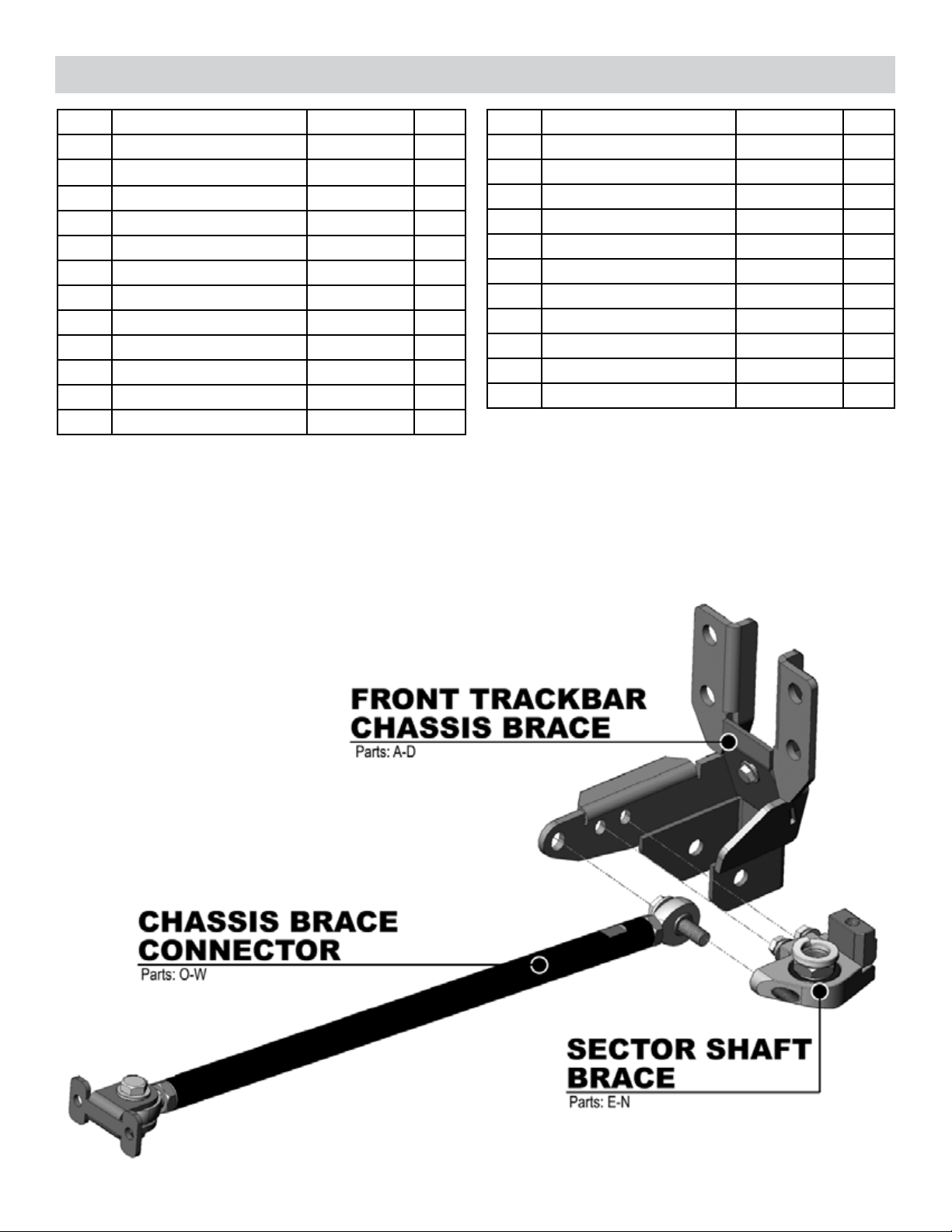
The Front Trackbar + Sector Shaft Reinforcement Kit actually consists of three intercon-
nected products, as illustrated below.
Description Part # QTY
M
3/8” Flat Washer 33082 2
N
3/8” Split Washer 33622 2
O
Chassis Connector Tube 03039 1
P
Frame Bracket 03040 1
Q
1/2” x 5/8” Rod End LXM8 -10 1
R
1/2” x 5/8” LH Rod End LXML8-10 1
S
5/8” Jam Nut 36264 1
T
5/8” LH Jam Nut 36964 1
U
1/2” x 2” GR5 Bolt 17211 2
V
1/2” Flat Washer 33086 4
W
1/2” Locking Nut 37308 2
To keep the parts organized, each product
has been individually packaged, and for ease
of tment, each product will be
installed separately.
For best results, please
follow the sequence
outlined in these
instructions.
2 Page
JKSOGS16 6
JKS Front Trackbar + Sector Shaft Reinforcement Installation
Page 3
Product:
Front Trackbar Chassis Brace
Installation
1. INSTALL TRACKBAR CHASSIS
BRACKET
Raise and support the vehicle with jack stands
positioned behind the front lower suspension arm
brackets.
Raise and support the front axle housing with a
hydraulic jack to relieve any tension from the track
bar mounting bolts.
Remove the nut and bolt that secures the front
track bar to the factory chassis bracket. Retain the
original hardware.
Remove the front track bar from the chassis
bracket.
Remove the four (4) steering box bolts.
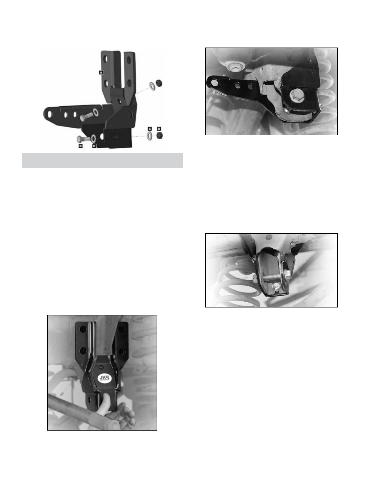
Position the Trackbar Chassis Bracket (A) over
your factory track bar bracket.
Insert OE track bar bolt (to keep mounting holes
aligned) and loosely install original nut. Do not
tighten.
Push the steering box as high on chassis as
mounting holes will allow and hold in position, then
tighten steering box mounting bolts until snug.
Insert a 7/16” x 1” Bolt (B) with 7/16” Flat Washer
(C) into each of the two holes in the factory track
bar bracket and through the Trackbar Chassis
Bracket (A). Secure each bolt with another 7/16”
Flat Washer (C) and 7/16” Locking Nut (D).
Tighten both 7/16” nuts to 50 ft-lbs. using a torque
wrench.
Tighten all four (4) steering box bolts to 70 ft-lbs.
using a torque wrench.
Re-insert the original steering box bolts and thread
into mounting holes by hand. Do not tighten yet.
JKSOGS16 6JKS Front Trackbar + Sector Shaft Reinforcement Installation
Page 3
Page 4
Product:
Sector Shaft Brace
Installation
2. PRE-FIT STEERING SECTOR PILLOW
BLOCK
Remove original pitman arm nut.
Install Sector Bearing Nut (G) with 7/8” Split
Washer (H) onto sector shaft. Tighten nut to 185
ft-lbs. using a torque wrench.
Place a 3/8” Split Washer (N) and 3/8” Flat Washer
(M) onto supplied 3/8” x 1” Bolts (L).
Slide Pillow Block assembly onto Sector Bear-
ing Nut (G) and insert both 3/8” Bolts through the
Trackbar Chassis Bracket (A) and into threaded
holes in Pillow Block to hold the assembly in position. Finger tighten bolts.
For alignment purposes, also insert one of the
1/2” x 2” Bolts (U) – supplied with Chassis Brace
Connector PN OGS164 – through Trackbar Chassis Bracket (A) and into the corresponding hole in
Pillow Block (E). Finger tighten 1/2” Bolt.
Raise the Steering Sector Pillow Block (E) as high
on Sector Bearing Nut (G) as possible. H I N T:
Holes in Trackbar Chassis Bracket are elongated
to compensate for factory variances on elevation
of steering box.
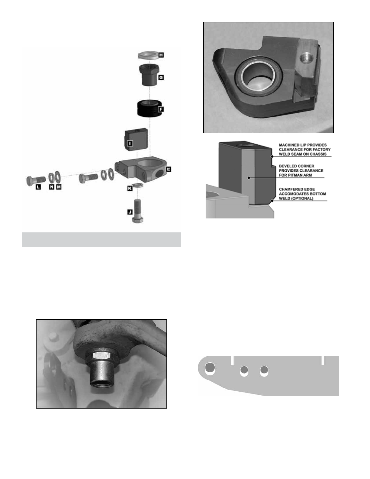
Loosely install Pillow Block Frame Mount (I) on
Steering Sector Pillow Block (E) with the 7/16” x
1-3/4” Bolt (J) and 7/16” Split Washer (K) exactly
as illustrated below.
4 Page
JKSOGS16 6
Make sure Steering Sector Pillow Block (E) is level
side-to-side.
JKS Front Trackbar + Sector Shaft Reinforcement Installation
Page 5
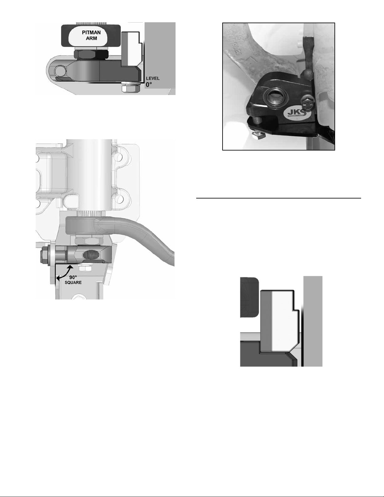
Make sure Steering Sector Pillow Block is square
to Trackbar Chassis Bracket (A). HINT: Pillow
block does not need to be perfectly level front-toback because Spherical Bearing (F) will compen-
sate for misalignment.
Once Steering Sector Pillow Block (E) is properly
positioned, add tension to both 3/8” x 1” Bolts (L)
and 1/2” x 2” Bolt (U) until snug to prevent Pillow
Block from accidentally moving.
3. INSTALL PILLOW BLOCK FRAME
MOUNT ON CHASSIS
With mounting bolts snug, turn your attention to
the Pillow Block Frame Mount (I). Make sure weldon mount is square to Pillow Block while positioned as close to chassis as possible.
HI N T: A small gap between the weld-on mount
and chassis is normal and acceptable.
If necessary, adjust front-to-back angle of Steer-
ing Sector Pillow Block until square with Trackbar
Chassis Bracket. HI N T: A pry bar may be useful
for applying leverage to pillow block while ne tuning the side-to-side or front-to-back alignment.
Use a marker or scribe to outline the location of
Pillow Block Frame Mount (I) onto chassis. Make
sure both sides and bottom of mount are clearly
transferred to chassis as this indicates where paint
needs to be removed prior to welding.
Remove the two 3/8” Bolts and 1/2” Bolt holding
the Pillow Block to Trackbar Chassis Bracket, and
slide the Pillow Block off of the Sector Bearing
Nut.
JKSOGS16 6JKS Front Trackbar + Sector Shaft Reinforcement Installation
Page 5
Page 6
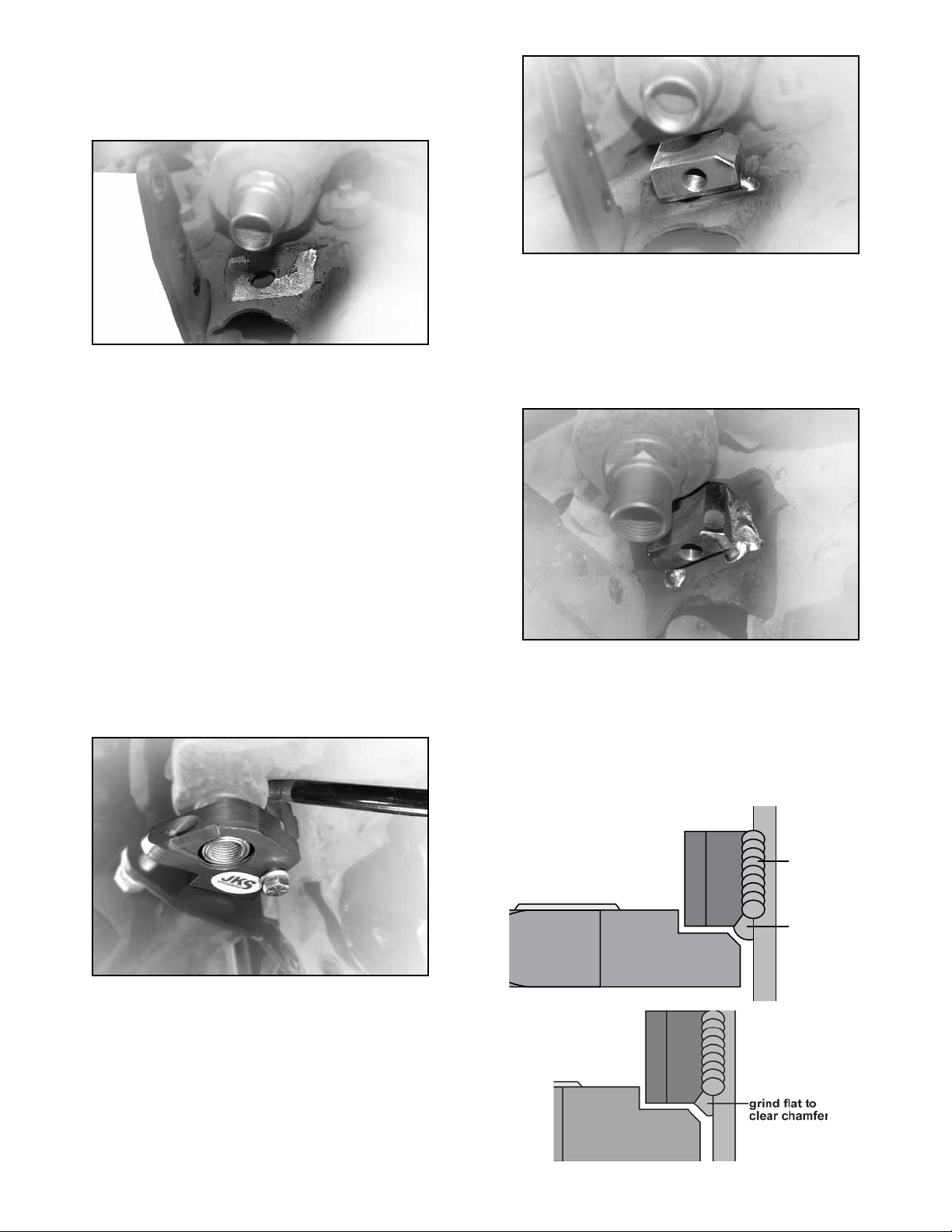
Remove paint from area on chassis where edges
horizontal
weld (bottom)
vertical
weld (side)
chassis
of Pillow Block Frame Mount (I) are marked. HINT:
If you cannot reach the area with a sanding tool, a
piece of emory cloth or sandpaper may be useful.
With bare metal exposed on chassis, the Steer-
ing Sector Pillow Block (E) must be re-installed so
that the Pillow Block Frame Mount (I) can be tack
welded in place. Slide the Pillow Block assembly
back onto the Sector Bearing Nut (G) and re-insert
the two 3/8” Bolts (L) and 1/2” Bolt (U) to hold the
Pillow Block in position.
Re-adjust the Steering Sector Pillow Block (E) until
level side-to-side and square to Trackbar Chassis
Bracket (A) as before.
Once the Pillow Block is properly positioned, add
tension to the two 3/8” Bolts (L) and 1/2” Bolt (U)
until snug to prevent the Pillow Block from accidentally moving.
With mounting bolts snug, make sure the Pillow
Block Frame Mount (I) is square to Pillow Block
and positioned as close to chassis as possible.
Remember, a small gap between the weld-on
mount and chassis is normal and acceptable.
Make sure you can access both sides of Frame
Mount (I) with welder. If necessary, the Trackbar
Chassis Bracket (A), Sector Bearing Nut (G) and/or
pitman arm can be temporarily removed for better
accessibility.
Completely weld both sides of Pillow Block Frame
Mount (I) to chassis.
Bottom of Frame Mount may also be welded to
chassis as long as bead does not interfere with
re-installation of Pillow Block. H I NT: Edges of
weld-on mount and Pillow Block are chamfered
to provide clearance for small weld bead. If weld
bead interferes with re-installation of Pillow Block,
you must remove any protrusions using a grinding
wheel for proper tment.
While holding the Frame Mount (I) in place, care-
fully tack weld both sides of the weld-on mount
directly to the chassis. H INT: It may be helpful to
apply slight pressure from above using a pry bar to
ensure Frame Mount remains ush against Pillow
Block.
Once the Frame Mount (I) is securely tacked in the
desired position, remove the two 3/8” Bolts and
1/2” Bolt and slide the Sector Shaft Pillow Block off
of the Sector Bearing Nut.
6 Page
JKSOGS16 6
JKS Front Trackbar + Sector Shaft Reinforcement Installation
Page 7
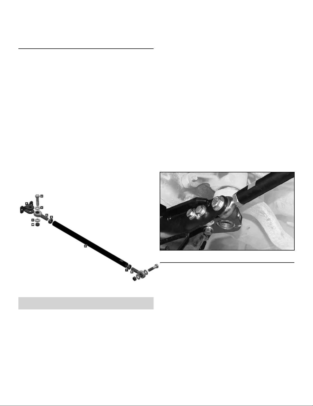
Allow welded area to cool. Then apply black spray
paint to Frame Mount (I) and any bare metal to
protect the surfaces from corrosion.
4. INSTALL STEERING SECTOR PILLOW
BLOCK
Apply a small amount of anti-seize lubricant to
threads of two 3/8” x 1” Bolts (L) and 1/2” x 2” Bolt
(U).
Slide Steering Sector Pillow Block (E) onto Sec-
tor Bearing Nut (G) and loosely install the two 3/8”
Bolts (L) and 1/2” Bolt (U). Do not tighten bolts yet.
Next insert the 7/16” x 1-3/4” Bolt (J) with 7/16”
Split Washer (K) into hole in Pillow Block. Thread
the 7/16” Bolt into Pillow Block Frame Mount (I) by
hand, but do not tighten yet.
Starting with the two 3/8” Bolts (L), slowly and
evenly tighten all four mounting bolts until snug. Do
not fully tighten any of the four mounting bolts yet.
(O). Leave approximately 1/2” of thread showing
between ends of tube and jam nuts.
Remove the 1/2” x 2” Bolt (U) from the Steering
Sector Pillow Block (E). Then loosen both 3/8” x 1”
Bolts (L) and the 7/16” Bolt (J) just enough to allow
the Rod End (Q or R) to be inserted between the
Chassis Bracket and Pillow Block.
Locate the slotted end of the Chassis Connector
Tube (O) and slide the rod end closest to it between the Chassis Bracket and Pillow Block. Re-
insert the 1/2” x 2” Bolt (U) and nger tighten.
Starting with the two 3/8” Bolts (L), slowly and
evenly tighten all four mounting bolts until snug. Do
not tighten only one bolt at a time – all bolts should
be tightened together.
Using a torque wrench, continue to tighten the two
3/8” Bolts (L) to 35 ft-lbs., and tighten the 7/16”
Bolt (J) to 50 ft-lbs. Do not fully tighten the 1/2”
Bolt (U) until specied later in these instructions.
HI N T: The extra 1/2” Locking Nut (W) & 1/2” Flat
Washer (V) supplied with Front Trackbar Chassis
Brace are not used when mounting to Steering
Sector Pillow Block (E).
Product:
Chassis Brace Connector
Installation
5. MOUNT CONNECTOR TO CHASSIS
BRACKET
6. MOUNT CONNECTOR TO
PASSENGER-SIDE CHASSIS RAIL
On opposite end of Chassis Connector Tube (O),
install weld-on Frame Bracket (P) using a 1/2” x 2”
Bolt (U), two 1/2” Flat Washers (V) and 1/2” Locking Nut (W). Tighten hardware until snug.
Position Frame Bracket (P) on passenger-side
chassis rail with bottom of mounting ange located
just above radius on chassis.
Assemble Chassis Brace Connector by completely
threading a 5/8” Jam Nut (S and T) onto each 1/2”
x 5/8” Rod End (Q and R), and then inserting a rod
end into each end of the Chassis Connector Tube
JKSOGS16 6JKS Front Trackbar + Sector Shaft Reinforcement Installation
Page 7
Page 8
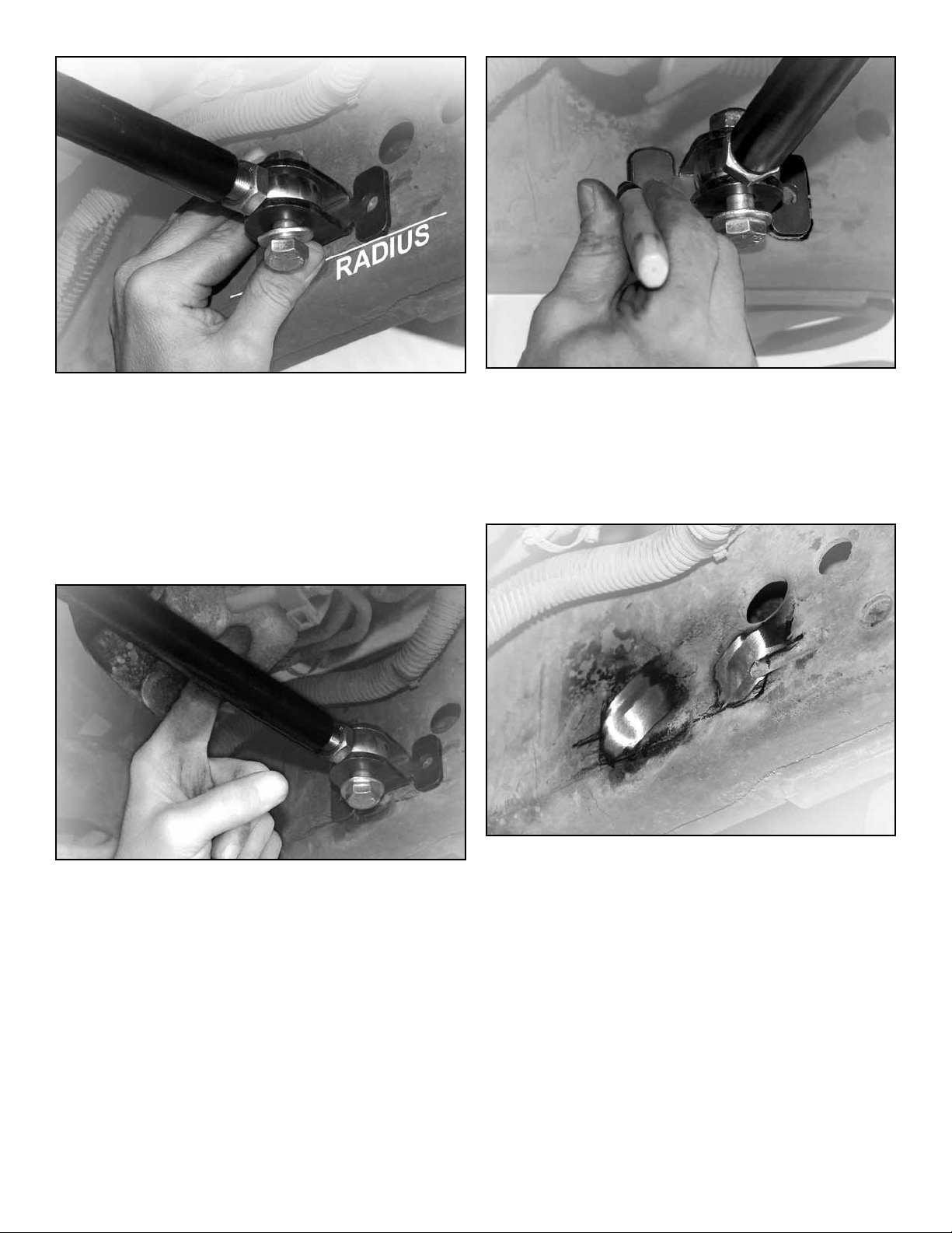
On factory 6-cylinder engine applications, Frame
Bracket (P) should be located directly across from
driver-side mounting point.
On Hemi 8-cylinder engine applications, Frame
Bracket (P) should be located further toward rear
of vehicle to allow Chassis Connector Tube (O) to
clear the engine oil lter. Leave enough distance
between Connector Tube and lter to allow for
“engine torqueing”, and to accommodate oil lter
changes.
Twist the Chassis Connector Tube (O) in opposite
direction to shorten the member and move the
Frame Bracket (P) out of position.
Remove any paint from area on chassis where lo-
cation of plug weld holes are marked. HINT: A die
grinder with a sanding wheel is useful for removing
paint from chassis.
Photos in this document illustrate installation on
Hemi 8-cylinder application.
Make sure 1/2” x 5/8” Rod Ends (Q and R) do not
bottom out on either Trackbar Chassis Bracket (A)
or weld-on Frame Bracket (P).
Twist the Chassis Connector Tube (O) to lengthen
the member until Frame Bracket (P) is pressed
rmly against desired mounting location on chassis.
Transfer perimeter of mounting anges and
location of plug weld holes onto chassis using a
marker or scribe.
8 Page
JKSOGS16 6
Reposition Frame Bracket (P) and lengthen the
Chassis Connector Tube (O) until weld-on bracket
is pressed rmly against desired mounting location
on chassis.
Tack weld Frame Bracket (P) to chassis rail.
Remove the 1/2” hardware that secures the Rod
End to Frame Bracket (P) and move the Chassis
Connector Tube (O) out of position for easier access to plug weld holes.
JKS Front Trackbar + Sector Shaft Reinforcement Installation
Page 9
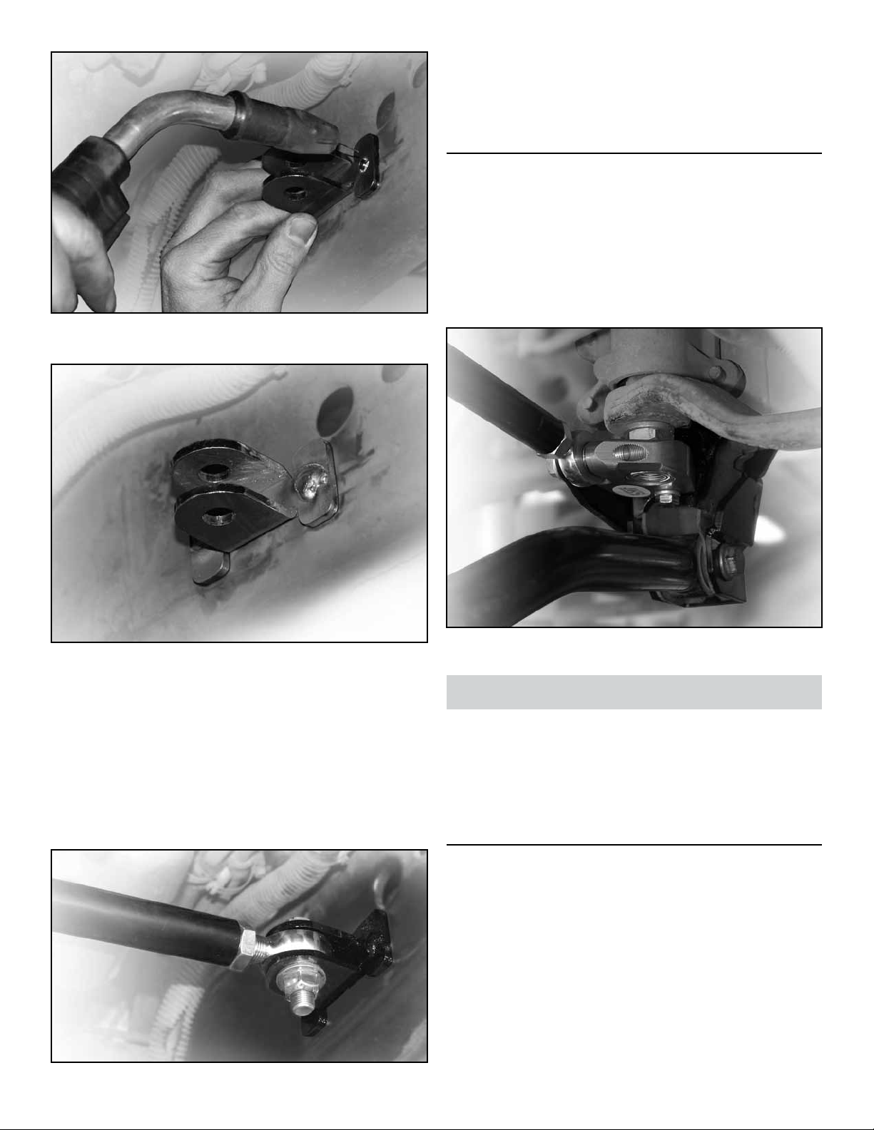
Fuse the Frame Bracket (P) to chassis by plug
welding each side of the mounting ange.
Using a torque wrench, tighten the 1/2” x 2” Bolt
(U) on passenger-side to 60 ft-lbs. Tighten the
other 1/2” x 2” Bolt (U) that threads into the alumi-
num Steering Sector Pillow Block (E) to 35 ft-lbs.
7. RE-INSTALL TRACK BAR
Apply anti-seize lubricant to bolt threads of original
track bar mounting hardware.
Re-install the track bar at the chassis bracket.
Insert the original bolt and nut and lightly snug the
hardware. Do not tighten original track bar hardware until vehicle has been lowered and suspension is supporting full vehicle weight.
Allow welded area to cool. Then apply black spray
paint to Frame Bracket and any bare metal to protect the surfaces from corrosion.
Move Chassis Connector Tube (O) back into posi-
tion and secure Rod End to Frame Bracket (P).
Tighten hardware until snug.
If necessary, twist Chassis Connector Tube (O)
until you reach neutral resistance.
Fully tighten both 5/8” Jam Nuts (S and T) against
Chassis Connector Tube (O).
Lower vehicle to ground and tighten track bar bolt
to 125 ft-lbs.
Maintenance
Check torque specications regularly.
Regular cleaning with pressurized water is recom-
mended to maximize reliability.
©2013 JKS Manufacturing, Inc & Aftermarketing, LLC
Revision Date 09/08/2014
JKSOGS16 6JKS Front Trackbar + Sector Shaft Reinforcement Installation
Page 9
 Loading...