

Page 1
INSTALLATION
INSTRUCTIONS
517-278-1226 • [email protected] • www.jksmfg.com
491 W. Gareld Avenue, Coldwater, MI 49036
Product: Front Trackbar Brace
Part Number: JKSOGS161
Applications: Jeep Wrangler JK, 2007+ (front)
Welcome
CONGRATULATIONS on purchasing a new Front Trackbar
Brace from JKS Manufacturing. We are committed to
providing you with the best products available and your
satisfaction is our rst priority.
PLEASE READ these Installation Instructions carefully,
and save them for future reference, as they contain important installation and maintenance information.
Important
INSTALLATION REQUIRES WELDING by a qualied
welder or metal fabricator.
JKS ADJUSTABLE TRACKBAR IS REQUIRED if existing track bar interferes with steering damper.
Tools Required
Hydraulic Floor Jack & Jack Stands
Metric/Standard Socket Wrench Set
Black Felt Tip Marker (or equivalent)
Torque Wrench
Die Grinder with Sanding Wheel
(or equivalent tool for removing paint)
Welding Equipment
Weldable Corrosion Resistant Coating,
3M® PN 05917 (or equivalent)
Satin Black Spray Paint
Anti-Seize Lubricant *
Factory Service Manual (recommended)
* Asterisk denotes tools that are not required for some applica-
tions. Thoroughly read instructions rst to determine which tools
will be required for your application.
Parts
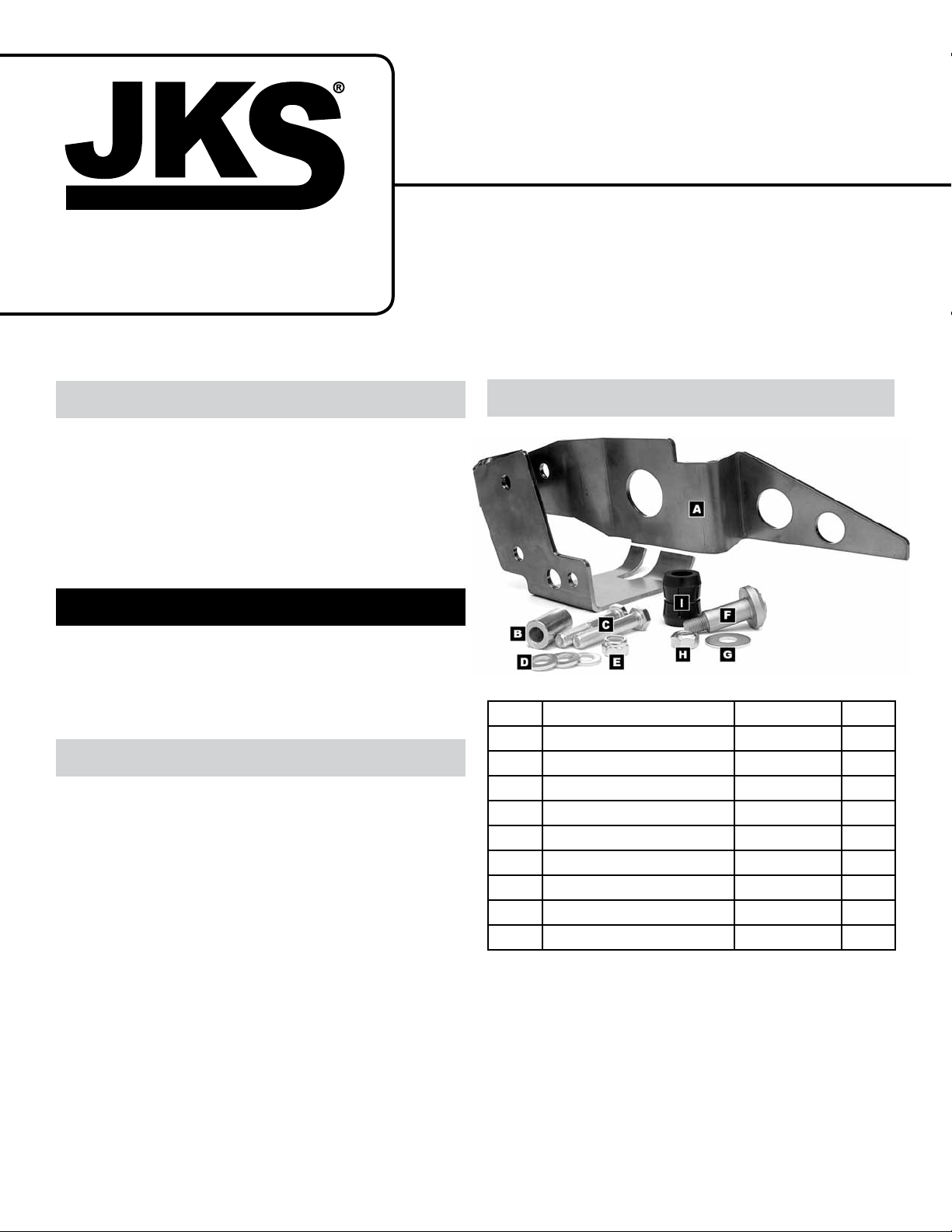
Description Part# QTY
A
Front Trackbar Brace 03030 1
B
Steel Sleeve 123 1
C
M14 x 80mm Bolt 1111329 0 2
D
9/16 SAE Washer W96S 3
E
M14 Nylock Nut 11129 042 1
F
Stabilizer Stud 103031 1
G
7/16” Fender Washer 33010 1
H
7/16” Locking Nut 37306 1
I
5/8” Poly Bushing 2611 1
JKSOGS161JKS Front Trackbar Brace Installation
Page 1
Page 2
Installation
1. REMOVE FRONT TRACK BAR
Raise and support vehicle chassis with jack
stands positioned behind the front lower suspension arm brackets.
Raise and support front axle housing with a hy-
draulic jack just enough to relieve any tension from
the track bar mounting bolts.
Remove front track bar mounting hardware from
axle and chassis brackets per the factory service manual instructions for your vehicle. Retain
original hardware and remove front track bar from
vehicle.
Remove steering damper mounting hardware from
the axle housing and tie rod. Remove steering
damper from vehicle and retain original hardware.
Prime entire surface of Trackbar Brace with 3M®
Weldable Corrosion Resistant Coating (or equivalent – must be weldable).
and temporarily tighten to hold the brace securely
to the factory bracket.
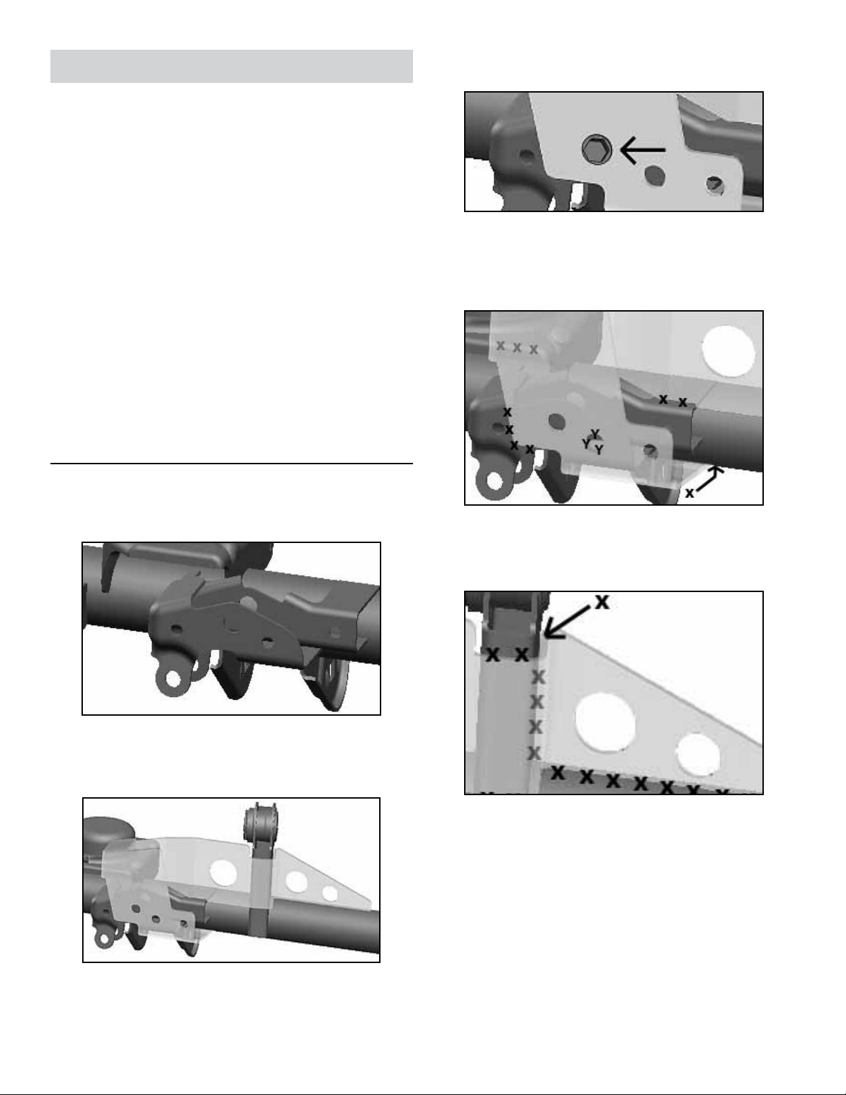
To prepare for welding, clearly mark the weld
locations directly on the axle housing as indicated in the following two illustrations. H I N T: A
felt tip marker is useful for marking locations to be
welded.
2. PREPARE AXLE FOR WELDING
To ensure a proper t, clean any dirt, debris or
grease from surface of factory track bar bracket.
Slide Trackbar Brace over factory track bar
bracket as illustrated. H I N T: Trackbar Brace is de-
signed to provide a snug t and may require some
persuasion to maneuver into position.
H I N T: Be sure to include area on lower spring mount
where it makes contact with Trackbar Brace. Also include
back side of axle tube where Trackbar Brace wraps under-
neath.
HINT: Include area on vertical upper control arm mount.
Remove Trackbar Brace and thoroughly clean lo-
cations on axle housing marked by an “X” or a “Y”.
H I N T: A die grinder with sanding wheel or similar
tool is useful for removing paint from axle housing.
IMPORTANT: The Trackbar Brace must be welded to
bare metal. Remove any paint, rust or other contaminants before welding.
With Trackbar Brace in position, insert one M14
x 80mm Bolt (C) into original mounting hole as
illustrated below. Secure bolt with original ag nut
2 Page
JKSOGS161
JKS Front Trackbar Brace Installation
Page 3
3. WELD TRACKBAR BRACE TO AXLE
HOUSING
With all indicated surfaces prepped for welding, re-
position Trackbar Brace on axle housing. Reinstall
the M14 x 80mm Bolt (C) and original ag nut to
secure the brace in position.
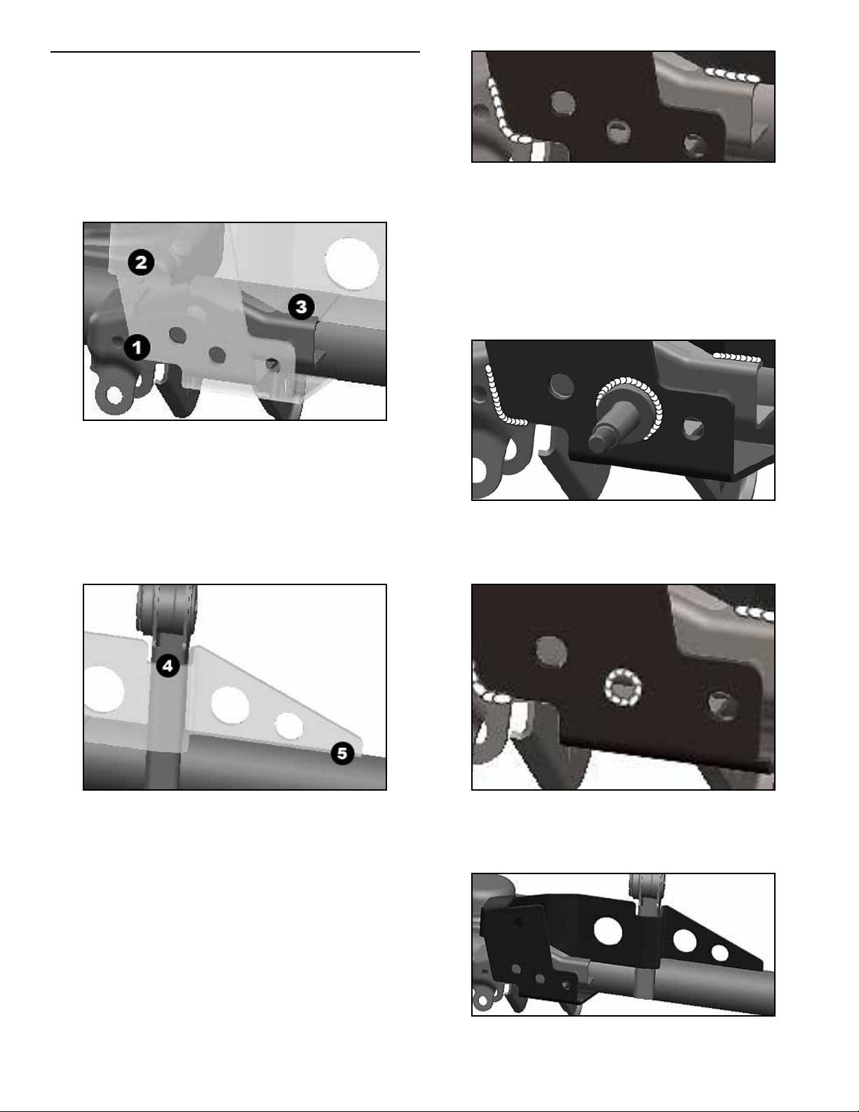
Tack weld Trackbar Brace to axle in the exact
sequence indicated below.
1. Tack weld front of Trackbar Brace to factory track
bar bracket.
2. Tack weld back of Trackbar Brace to lower coil
spring mount.
3. While pushing Trackbar Brace against vertical upper control arm mount to minimize gap at location
"4", tack weld front of brace to factory track bar
bracket.
IMPORTANT: Avoid overheating axle tube and rubber
bushing in vertical upper control arm mount by welding a small section and allowing the surface to cool off
regularly.
To install supplied weld-on Steering Stabilizer
Mount (optional), position base of Stabilizer Stud
(F) in middle hole of Trackbar Brace as illustrated
below. Weld base of Stabilizer Stud to Trackbar
Brace.
If you are not installing the optional steering sta-
bilizer mount, plug weld Trackbar Brace to factory
trackbar mounting bracket at location indicated by
a “Y” in step 2.
4. While pushing Trackbar Brace against axle tube
to minimize gap at location "5", tack weld front of
brace to vertical upper control arm mount.
5. Finally, tack weld end of Trackbar Brace to axle
tube.
Next, llet weld Trackbar Brace to axle housing
at all locations indicated by an “X” in step 2. Do
not weld location indicated by “Y” if you plan
to install supplied Steering Stabilizer Mount
(optional)
Once all welding is complete, spray paint entire
Trackbar Brace and any bare metal on axle housing to prevent corrosion. All exposed metal must
be completely covered.
JKSOGS161JKS Front Trackbar Brace Installation
Page 3
Page 4
4. REINSTALL FRONT TRACK BAR
Apply anti-seize lubricant to bolt threads of track
bar mounting hardware.
Insert axle end of track bar into reinforced axle
bracket rst and loosely install M14 x 80mm Bolt
(C), 9/16" SAE Washer (D) and original ag nut
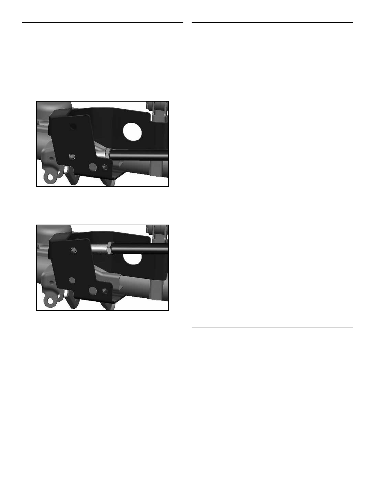
H I N T: Use the lower mounting hole if steering linkage is in
the factory position…
…or use the upper mounting hole if vehicle has a “drag
link ip” or high-steering conversion. When track bar is
installed in the upper hole, supplied steel sleeve must be
installed in the lower hole using hardware provided.
Mount chassis end of track bar and loosely install
original mounting hardware. Vehicle must be on
level ground with coil springs supporting the
full vehicle weight before mounting hardware
is tightened.
Using a torque wrench, tighten mounting hardware
at both ends of track bar to 125 ft-lbs.
Insert Steel Sleeve (B) into unused track bar
mounting hole. Secure sleeve by installing remaining M14 x 80mm Bolt (C), 9/16" SAE Washer (D)
and M14 Nylock Nut (E).
Using a torque wrench, tighten Steel Sleeve (B)
mounting bolt to 125 ft-lbs.
5. REINSTALL STEERING DAMPER
If you chose to relocate the axle end of your steering
damper by installing the optional stabilizer mount, then
the factory mounting position on the axle housing will no
longer be used.
Simply install the body end of steering damper to new
stabilizer mount using the supplied 7/16” Fender Washer
(G) and 7/16” Locking Nut (H). If original damper bushing
does not t snugly on Stabilizer Stud (F), replace it with the
supplied 5/8” Poly Bushing (I). Otherwise follow the instructions below.
Secure body end of steering damper to appropri-
ate mounting point on axle housing.
It is the responsibility of the installer to ensure the
steering damper is mounted properly to the axle
housing, and is the appropriate size for the mounting position used.
If you relocated the axle end of steering damper,
remove the U-bolts that secure the factory steering
damper bracket to the tie rod and spin the bracket
180 degrees so the mounting stud is located on
passenger side of U-bolts. If axle end of steering
damper remains in the factory position, disregard
this step as well as the following step.
Reinstall the U-bolts and nger tighten hardware
so that factory steering damper bracket can slide
freely on tie rod. Determine the appropriate mounting position and tighten the original hardware to
factory torque specications.
Mount shaft end of steering damper to bracket on
tie rod using original mounting hardware.
Tighten hardware to factory torque specications.
If no longer being used, you may remove original
steering damper mounting tabs from axle housing
for improved clearance.
©2014 JKS Manufacturing, Inc & Aftermarketing, LLC
Revision Date 07/31/2014
4 Page
JKSOGS161
JKS Front Trackbar Brace Installation
 Loading...