

Page 1
INSTALLATION
INSTRUCTIONS
517-278-1226 • [email protected] • www.jksmfg.com
491 W. Gareld Avenue, Coldwater, MI 49036
Product: Adjustable Trackbar
Part Number: JKSOGS155
Welcome
CONGRATULATIONS on purchasing a new Adjustable
Trackbar from JKS Manufacturing. We are committed to
providing you with the best products available and your
satisfaction is our rst priority.
PLEASE READ these Installation Instructions carefully,
and save them for future reference, as they contain important installation and maintenance information.
Important
NOT COMPATIBLE WITH right hand drive vehicles.
CHECK TORQUE SPECIFICATIONS regularly.
Tools Required
Metric/Standard Socket Wrench Set
Torque Wrench
Tape Measure
1-1/2” Open-End Wrench
Heavy Duty Ratchet Strap *
Anti-Seize Lubricant
Hydraulic Press *
Wheel Bearing Grease
* Asterisk denotes tools that are not required for some applica-
tions. Thoroughly read instructions rst to determine which tools
will be required for your application.
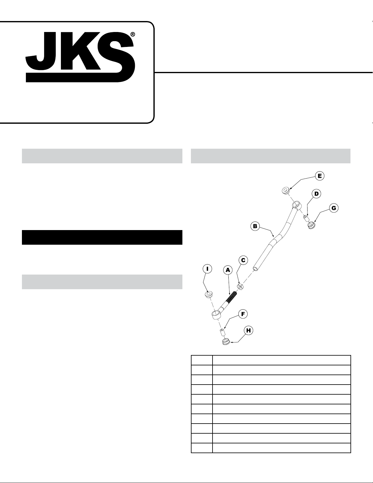
Description
A
Male Threaded (Axle) End
B
Female Threaded (Chassis) End
C
1” NF Jam Nut
D
Sleeve
E
Polyurethane Bushing
F
Sleeve
G
Polyurethane Bushing
H
Polyurethane Bushing
I
Polyurethane Bushing
Parts
JKSOGS155JKS Adjustable Trackbar Installation
Page 1
Page 2
Installation
1. REMOVE ORIGINAL EQUIPMENT (OE)
REAR TRACK BAR
Remove rear track bar and mounting hardware
per factory service manual instructions for your
vehicle. Retain original mounting hardware as it is
required for Adjustable Trackbar installation.
HINT: The original trackbar bushings may be
retained as spares for your Adjustable Trackbar if
replacement parts are ever needed. See Maintenance section for details.
2. LUBRICATE BUSHINGS AT BOTH ENDS
OF ADJUSTABLE TRACKBAR
Locate bag of parts containing Polyurethane
Bushings (E, G, H, & I) and Sleeves (D & F).
Liberally apply wheel bearing grease to surface of
bushings.
Assemble Polyurethane Bushings and Sleeves
at each end of trackbar as indicated in the parts
diagram to the left.
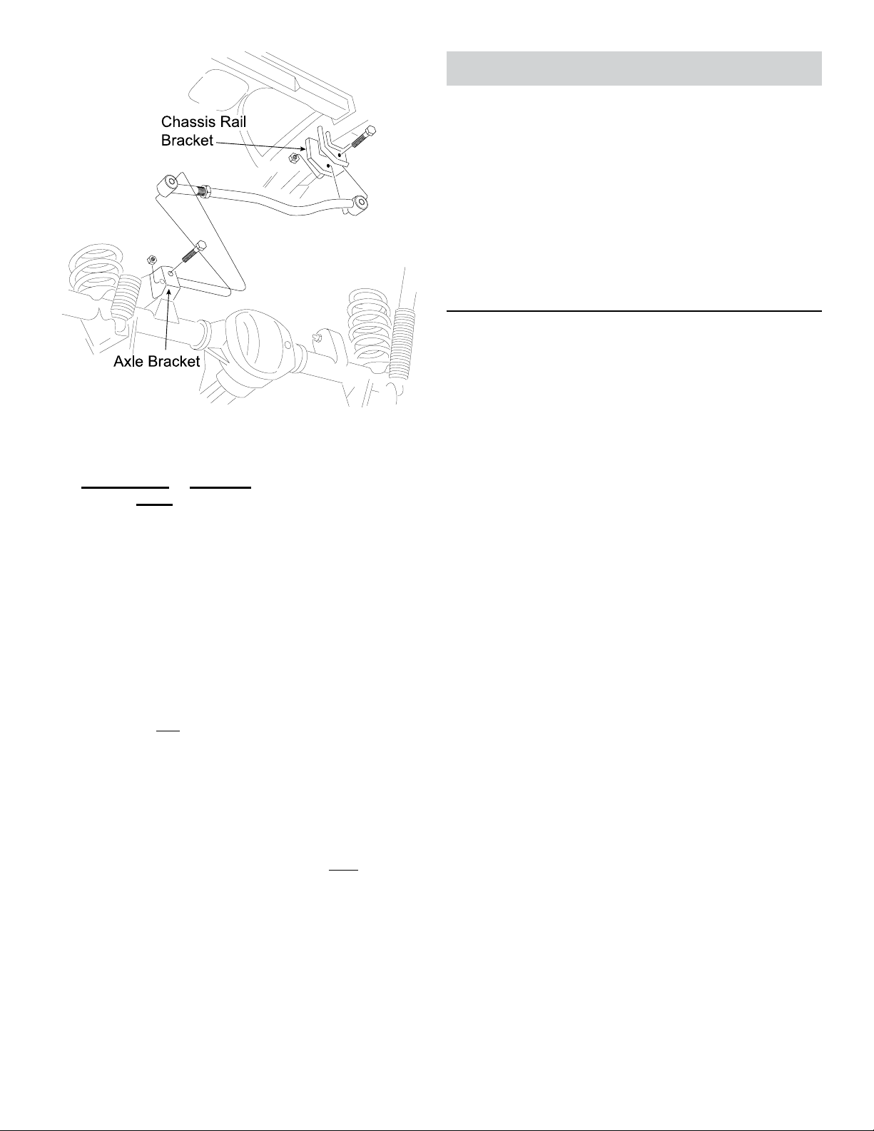
3. MOUNT ADJUSTABLE TRACKBAR TO
CHASSIS BRACKET
Mount Chassis End (B) of Adjustable Trackbar
to chassis rail bracket and temporarily secure
with original mounting hardware. Apply anti-seize
lubricant to bolt threads. H I NT: When installed
correctly, the curve in Adjustable Trackbar should
point toward front of vehicle.
If the two measurements are equal, the axle is
centered. If measurements vary, divide the difference in half to determine the amount of adjustment
required. HINT: If axle housing is not centered, the
chassis can be laterally shifted using either of the
following methods.
Ratchet Strap (preferred)
 Attach a heavy duty ratchet strap to the chassis
on one side of the vehicle, and to the axle housing
on the other side.
 Slowly tighten the strap in small increments to pull
the chassis in alignment with the axle. Take measurements after each adjustment until centered.
Pushing Vehicle Body
Although this method will laterally shift position of chassis
relative to axle housing, it does not enable the position to
be easily stabilized while measurements are taken.
 With the vehicle safely on the ground, have a
partner gently push on the vehicle body above the
rear wheels.
4. CENTER REAR AXLE HOUSING
The rear axle housing must be in perfect lateral alignment
with vehicle chassis before Adjustable Trackbar installation
can be completed.
Before you center the axle housing, make sure the
vehicle is at normal ride height, on level ground,
with the suspension supporting the full vehicle
weight.
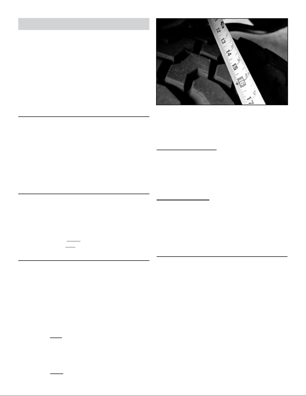
Determine if axle housing is centered by measur-
ing the distance between the tire and chassis,
using exact same points on each side of vehicle to
ensure accuracy.
HINT: For example, measure from the edge of a
tire tread lug to the outboard side of chassis, then
repeat the measurement on other side of vehicle
using exact same points.
2 Page
JKSOGS155
5. SET ADJUSTABLE TRACKBAR LENGTH
AND MOUNT TO AXLE
IMPORTANT: Length of Adjustable Trackbar must be
set with axle housing perfectly centered and vehicle at
normal ride height.
With axle housing centered beneath the chassis,
adjust length of Adjustable Trackbar by rotating
Axle End (A) until the Bushing Sleeve (F) aligns
with mounting holes on axle bracket.
JKS Adjustable Trackbar Installation
Page 3
IMPORTANT: If Bushing Sleeve at Axle End is not
parallel with axle bracket mounting holes, rst conrm
that factory bend in Axle End of trackbar is pointing
towards the front of vehicle. If Bushing Sleeve is still
out of alignment, it may be necessary to slightly bend
Axle End of trackbar using a hydraulic press. Variations in the axle bracket position are typically the
result of modications to related suspension parts
Maintenance
Check torque specications regularly.
Regular cleaning with pressurized water is recommended
to maximize reliability.
The original equipment trackbar uses the same bushing
size as the JKS Adjustable Trackbar. Upon removal of the
original trackbar, the OE bushings should be retained if in
good condition. In the unlikely event that the Adjustable
Trackbar bushings wear out, the OE trackbar bushings
may be used as replacements.
©2013 JKS Manufacturing, Inc & Aftermarketing, LLC
Revision Date 10/31/2013
HINT: The factory rear trackbar bracket on axle utilizes a
“pocket” design that requires the Adjustable Trackbar be
removed from the chassis bracket before Axle End (A) can
be inserted. This may not be necessary if an aftermarket
extension bracket has been installed on the factory axle
bracket.
Apply anti-seize lubricant to original mounting bolt
threads and adjustment threads of trackbar.
Install Axle End (A) of Adjustable Trackbar to the
axle bracket by securing with the original mounting
hardware.
Take measurements again to ensure axle housing
is perfectly centered and make any nal adjustments if necessary.
Once all adjustments are complete, fully tighten
the Jam Nut (C) to prevent Adjustable Trackbar
length from changing. H I N T: It may be easier
to tighten Jam Nut with the Adjustable Trackbar
removed from the vehicle.
Tighten mounting bolts on axle bracket and chas-
sis rail bracket to 50 ft-lb. using a torque wrench.
JKSOGS155JKS Adjustable Trackbar Installation
Page 3
 Loading...