

Page 1
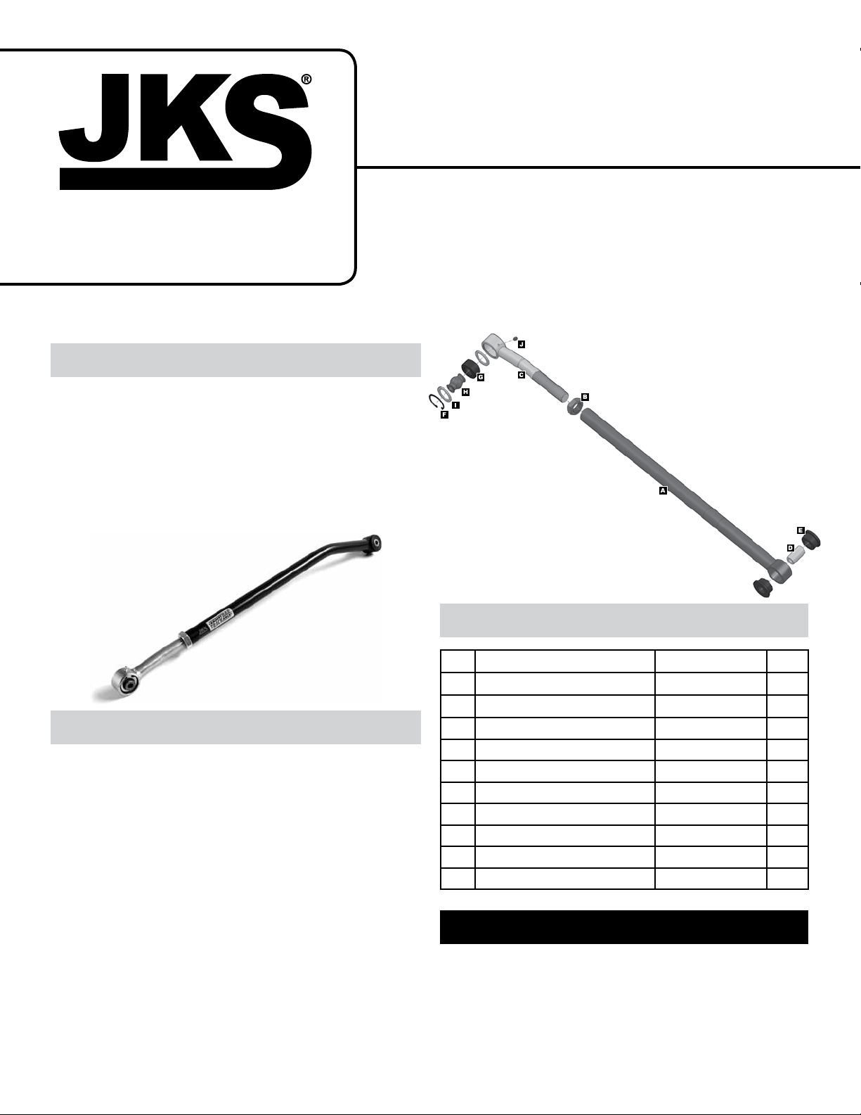
Product: Adjustable Track Bar
Part Number: JKSOGS151
Applications: Wrangler TJ, 1997-06 (rear only)
INSTALLATION
INSTRUCTIONS
517-278-1226 • [email protected] • www.jksmfg.com
491 W. Gareld Avenue, Coldwater, MI 49036
Welcome
CONGRATULATIONS on purchasing a new Adjustable
Trackbar from JKS Manufacturing. We are committed to
providing you with the best products available and your
satisfaction is our rst priority.
PLEASE READ these Installation Instructions carefully,
and save them for future reference, as they contain important installation and maintenance information.
Tools Required
Hydraulic Floor Jack & Jack Stands
Metric/Standard Socket Wrench Set
Torque Wrench
1-1/2” Open-End Wrench
T55 Torx Driver (for OE track bar bolt)
Tape Measure
Heavy Duty Ratchet Strap *
Anti-Seize Lubricant
Grease Gun with Zerk Fitting Coupler
Wheel Bearing Grease
* Asterisk denotes tools that are not required for some applica-
tions. Thoroughly read instructions rst to determine which tools
will be required for your application.
JKSO GS151JKS Adjustable Track Bar Installation
Parts
Description Part No. QTY
A
Female Threaded (Chassis) End 03053
B
1” NF Jam Nut 36270
C
Male Threaded (Axle) End 03054
D
Sleeve 138
E
Polyurethane Bushing Half M03618-BK-01
F
Snap Ring CE91125
G
Spherical Bushing CEES9385
H
Spherical Ball CE9112 25
I
Retaining Washer CE91126GM
J
Grease Zerk 7201
1
1
1
1
2
1
1
1
2
1
Important
VEHICLE MUST BE EQUIPPED with a CV type
driveshaft if installing this product with angled relocation bracket on axle housing.
NOT COMPATIBLE WITH right hand drive vehicles.
CHECK TORQUE SPECIFICATIONS regularly.
Page 1
Page 2
Installation
1. REMOVE REAR TRACK BAR
Raise and support vehicle chassis with jack
stands positioned in front of the rear lower suspension arm brackets. Remove rear wheels from
vehicle.
Raise and support axle housing with a hydraulic
jack. H I NT: To relieve tension from mounting bolts,
axle should be evenly supported with suspension
at normal ride height.
If equipped, remove and discard plastic dust shield
covering the bolt that secures rear track bar to the
OE bracket.
Remove rear track bar mounting hardware from
axle and chassis brackets. HINT: A T55 Torx
driver may be required to remove hardware.
Remove track bar from vehicle and retain hard-
ware.
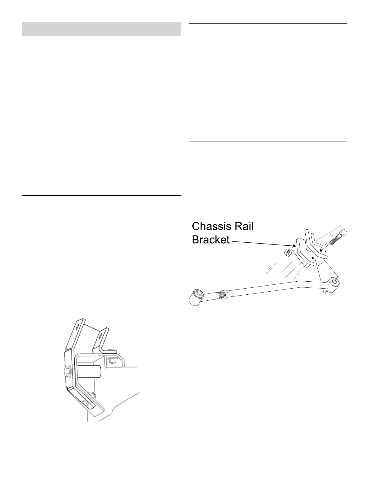
2. INSTALL ANGLED CV TRACK BAR
BRACKET (OPTIONAL)
If Adjustable Trackbar PN OGS151B was purchased, a
special Angled CV Bracket PN OGS160 was also supplied.
The purpose of this bracket is to re-establish proper alignment of the axle bracket with the track bar. This is necessary whenever the axle is rotated to align the pinion with a
CV type driveshaft.
3. LUBRICATE BUSHINGS AT EACH END
OF ADJUSTABLE TRACKBAR
Locate bag of parts containing Polyurethane
Bushing Halves (E) and Sleeve (D).
Liberally apply wheel bearing grease to surface of
bushings.
Assemble Polyurethane Bushing Halves (E) and
Sleeve (D) at Chassis End (A) of track bar as indicated in the parts diagram on page 1.
Using a Grease Gun with Zerk Fitting Coupler,
slowly inject wheel bearing grease into the Grease
Zerk (J) at Axle End (C) of track bar.
4. MOUNT ADJUSTABLE TRACKBAR TO
CHASSIS RAIL BRACKET
Apply anti-seize lubricant to bolt threads of original
track bar mounting hardware.
Mount Chassis End (A) of Adjustable Trackbar
to the chassis rail bracket and loosely install the
original mounting hardware. H I NT: When installed
correctly, the bend in Adjustable Trackbar should
point up.
If vehicle has already been equipped with a similar
aftermarket angled track bar bracket, disregard
this step and proceed to next section.
Install JKS Angled CV Track Bar Bracket PN
OGS160 (or equivalent) at this time, according to
the installation instructions provided with the part.
PN OGS160 is supplied with JKS Adjustable
Trackbar PN OGS151B, or available separately if
installing PN OGS151.
2 Page
5. CENTER REAR AXLE HOUSING
The rear axle housing must be in perfect lateral alignment
with vehicle chassis before Adjustable Trackbar installation
can be completed.
Re-install wheels and lower vehicle to ground.
IMPORTANT: Vehicle must be at normal ride
height, on level ground, with the suspension supporting the full vehicle weight.
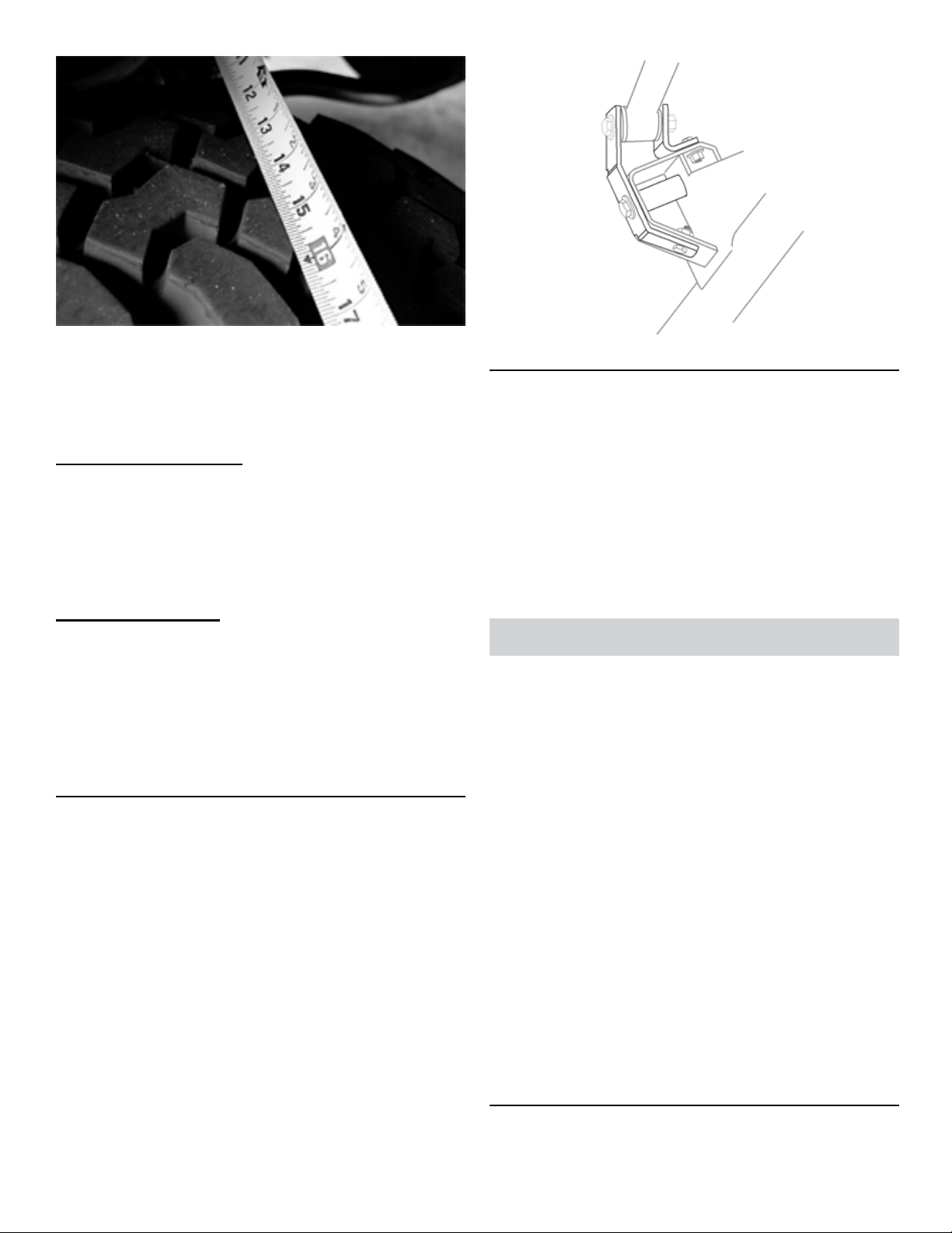
Determine if the axle housing is centered by mea-
suring the distance between the tire and chassis,
using the exact same points on each side of the
vehicle to ensure accuracy. HINT: For example,
measure from the edge of a tire tread lug to the
outboard side of the chassis, then repeat the measurement on the other side of vehicle using exact
JKSO GS151
same points.
JKS Adjustable Track Bar Installation
Page 3
If the two measurements are equal, the axle is
centered. If the measurements vary, divide the difference in half to determine the amount of adjustment required. HINT: If the axle housing is not
centered, the chassis can be laterally shifted using
either of the following methods.
Ratchet Strap (preferred)
 Attach a heavy duty ratchet strap to the chassis on
one side of the vehicle, and to the axle housing on
the other side.
 Slowly tighten the strap in small increments to pull
the chassis in alignment with the axle. Take measurements after each adjustment until centered.
Pushing Vehicle Body
Although this method will laterally shift position of chassis
relative to axle housing, it does not enable the position to
be easily stabilized while measurements are taken.
 With the vehicle safely on the ground, have a
partner gently push on the vehicle body above the
rear wheels.
7. POST-INSTALLATION
Take measurements again to ensure axle housing
is perfectly centered and make any nal adjustments if necessary.
Once all adjustments are complete, fully tighten
the Jam Nut (B) to prevent Adjustable Trackbar
length from changing. H I N T: It may be easier
to tighten Jam Nut with the Adjustable Trackbar
removed from the vehicle.
Using a torque wrench, tighten mounting hardware
at both ends of track bar to 74 ft-lbs.
Maintenance
Re-torque fasteners after driving 150 miles. Continue to
check torque specications as part of regular vehicle main-
tenance routine.
The Axle End (C) of the Adjustable Trackbar features a
spherical polyurethane bushing which is both greaseable
and rebuildable.
6. SET ADJUSTABLE TRACKBAR LENGTH
AND MOUNT TO AXLE
With the axle housing centered beneath the chas-
sis, adjust the length of Adjustable Trackbar by rotating the Axle End (C) until the Spherical Ball (H)
aligns with the mounting holes on the axle bracket.
Apply anti-seize lubricant to original mounting bolt
threads and adjustment threads of trackbar.
Install Axle End (C) of Adjustable Trackbar to the
axle bracket by securing with the original mounting
hardware.
JKSO GS151JKS Adjustable Track Bar Installation
Lubrication
Lubricate the bushing via the Grease Zerk (J)
regularly as part of vehicle maintenance schedule.
Use common wheel bearing grease or equivalent.
Replacement Parts
Bushings are designed for maximum longevity and
it is extremely unlikely that any parts will wear out.
Just in case, all replacement parts are available
directly from JKS Manufacturing on our website at
www.jksmfg.com.
Cleaning
Regular cleaning with pressurized water is recommended to maximize ease of operation and
reliability. Always lubricate afterwards to evacuate
any moisture
©2013 JKS Manufacturing, Inc & Aftermarketing, LLC
Revision Date 10/31/2013
Page 3
 Loading...