

Page 1
INSTALLATION
INSTRUCTIONS
517-278-1226 • [email protected] • www.jksmfg.com
491 W. Gareld Avenue, Coldwater, MI 49036
Product: B1 Body Lift
Part Number: JKS9901
Applications: CJ8, 1978-82
Welcome
Congratulations on purchasing a new B1 Body Lift from
JKS® Manufacturing. We are committed to providing you
with the best products available and your satisfaction is our
rst priority.
We hope you enjoy your JKS® purchase and are here to
help if you still have questions after reviewing this safety
information and instructions. Contact us online at www.
jksmfg.com or by phone at 877-533-7557.
Tools Required
Metric/Standard Socket Wrench Set
Torque Wrench
Tape Measure
Medium Strength Threadlocker
Hydraulic Floor Jack
Sturdy Block of Wood (to protect body)
Center Punch and Hammer
3/8” Drill Bit
1/8” Drill Bit or Torch * (for removing plastic rivets
in steering slip shaft)
Reciprocating Saw or Die Grinder with Cut-Off Wheel *
(for trimming fan shroud)
Wire Brush *
Factory Service Manual (recommended)
* Asterisk denotes tools that are not required for some applica-
tions. Thoroughly read instructions rst to determine which tools
will be required for your application.
Parts
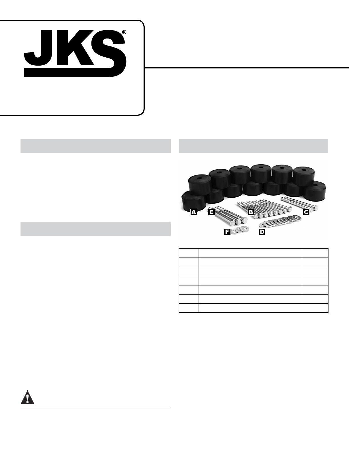
Description QTY
A
Dura-Thane™ Body Puck 13
B
3/8” x 3-1/2” Bolt 8
C
3/8” x 4” Bolt 2
D
3/8” Flat Washer 10
E
7/16” x 4” Bolt 3
F
7/16” Flat Washer 3
NOTICE
One Side At A Time
Body lift must be installed on one side of vehicle at a time.
CAUTION
Always Wear Protective Gear
Safety glasses and protective gloves are required.
JKS part numberJKS DESCRIPTION Installation
Page 1
Page 2
Important Product
Safety Information
For your safety and the safety of others, please read
all instructions and warnings in this pamphlet and your
Jeep® owner’s manual and off road driving supplement
before attempting installation. Within these instructions
the following signal words refer to important product
safety information:
WARNING
Indicates hazards or unsafe situations which could
result in severe personal injury or death.
CAUTION
Indicates hazards or unsafe situations which could result in property damage or minor to moderate personal
injury.
To reduce risk of serious injury and accident:
 Choose modications that balance your actual
highway & off-road use.
 Avoid sharp turns, abrupt maneuvers or steep
side-cambers.
 Avoid other maneuvering conditions which may
cause the vehicle to trip, roll, lose traction or compromise your ability to safely brake in an emergency.
 Routinely inspect your vehicle components for un-
usual wear or off-road damage. Repair or Replace
any unserviceable components before use.
 Do not modify or combine body lifts with other me-
chanical lifts contrary to manufacturers’ or Jeep®
recommendations & warnings.
 Acquaint any other drivers with your vehicle modi-
cations and handling.
 Always wear seat belts and/or appropriate off-road
restraints, reduce your speed, Tread Lightly©.
NOTICE
Careful attention is required to this operation that gener-
ally does not relate to personal injury, although damage
to your JKS product or other property may result if you
fail to follow instructions.
WARNING
Higher Rollover Risk
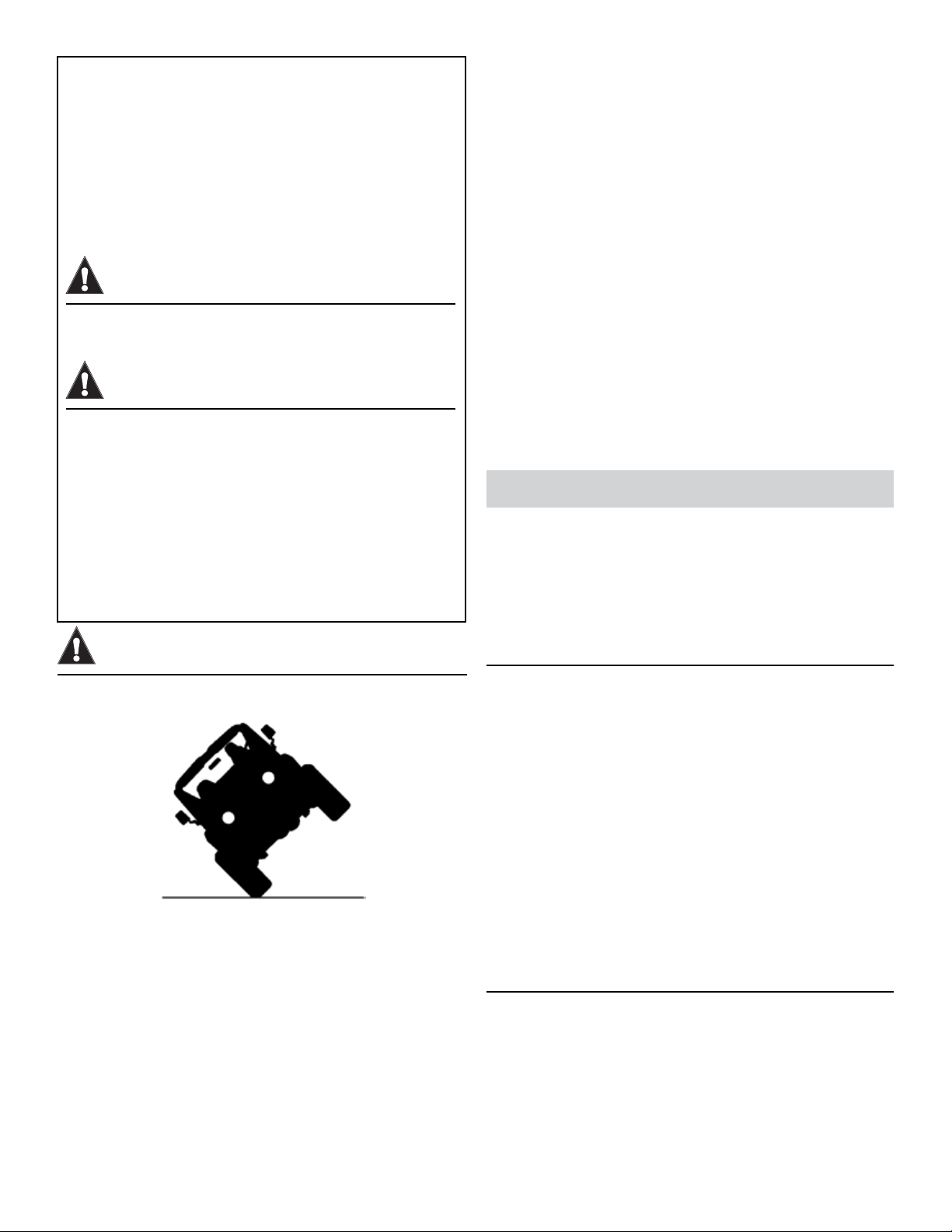
Modifying your Jeep® to improve off-road performance
may result in vehicle handling different than as factory
equipped, including increased ride-height and/or chassis articulation; reduced lateral stability and higher risk of
roll-over or other accident. Also, owner’s choice of larger
tire and wheel combinations may require additional braking
force or increased stopping distances.
Installation
1. UNBOLT FAN SHROUD
Remove the four bolts holding the plastic fan
shroud and radiator to the vehicle. Use the bolts to
temporarily support the radiator, and remove fan
shroud from vehicle.
2. LOOSEN BODY MOUNTS
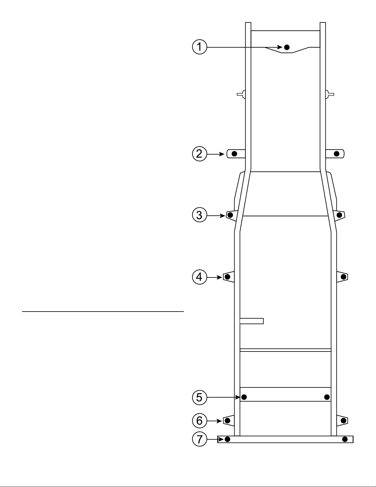
Locate all thirteen body mount bolts on vehicle.
Refer to the BODY MOUNT LOCATION DIAGRAM for assistance.
Loosen each body mount bolt, but DO NOT RE-
MOVE until instructed.
Remove the bolt from body mount 1 located
beneath the grill.
Remove bolts from body mounts 2 3 4 5 6
and 7 on DRIVER SIDE of vehicle only.
NOTE: Body mount 5 is located between fuel tank
and rear axle.
3. INSERT BODY PUCKS
Position a hydraulic jack next to body mount 3 on
DRIVER SIDE of vehicle.
Place a sturdy wooden block between the hydrau-
lic jack pad and channel portion of vehicle body
for protection.
2 Page
JKS part number
JKS DESCRIPTION Installation
Page 3
Carefully raise the vehicle body just enough to
insert 1.25” Body Pucks (A) between body and factory body mounts 2 3 4 5 6 and 7.
NOTE: Recessed bottom of Body Pucks must encapsulate factory body mounts.
With Body Pucks (A) inserted, slowly lower the
vehicle body onto mounts, ensuring correct align-
ment of body on chassis.
Apply medium strength thread locking compound
to four of the supplied 3/8” x 3-1/2” Bolts (B), one
of the 3/8” x 4” Bolts (C), and one of the 7/16” x 4”
Bolts (E).
Insert the 3/8” x 3-1/2” Bolts (B) with 3/8” Flat
Washers (D) into body mount positions 3 4 5,
and 6. Insert the 3/8” x 4” Bolt (C) with 3/8” Flat
Washer (D) into body mount position 2. Insert the
7/16” x 4” Bolt (E) with 7/16” Flat Washer (F) into
body mount position 7. Start threads but DO NOT
TIGHTEN bolts until instructed.
Repeat this procedure with body mounts 2 3
4 5 6 and 7 on the PASSENGER SIDE of
vehicle.
Insert the last remaining Body Puck (A) at body
mount 1 located beneath the grill.
Apply medium strength thread locking compound
to the last remaining 7/16” x 4” Bolt (E) and insert
with a 7/16” Flat Washer (F) into body mount posi-
tion 1.
Using a torque wrench, tighten all 3/8” and 7/16”
Bolts (B, C and E) to 30-35 ft-lbs.
NOTE: Use care when tightening bolts to avoid crushing factory rubber body mounts.
4. MODIFY FAN SHROUD
Locate the four mounting holes on the plastic fan
shroud.
Measure exactly 1” above the factory mounting
holes and mark the location with a center punch.
Drill a new 3/8” hole through all four center
punched marks.
NOTE: Grind away any plastic reinforcement webbing
that interferes with re-installation of mounting bolts.
Test t the fan shroud to the radiator by aligning
with the new mounting holes.
Check for interference between the fan shroud and
radiator hoses, fan blades, or any other objects. If
necessary, trim the fan shroud until it completely
clears any interferences.
Secure the fan shroud and radiator to the vehicle
with the original four mounting bolts.
JKS part numberJKS DESCRIPTION Installation
Page 3
Page 4

5. CHECK T-CASE OPERATION
Check operation of the shift lever to ensure the
transfer case fully engages all ranges.
NOTE: If necessary, adjust linkage between shift lever
and bell crank. If interference is experienced, it may
be necessary to trim the oor to provide sufcient
shift lever clearance.
6. CHECK FOR STEERING BIND
Drive vehicle a short distance while checking for
binding in the steering wheel. If no steering bind
exists, skip this section and proceed to step 7.
If steering bind exists, remove the steering slip
shaft from the vehicle and locate the two plastic
rivets that prevent it from slipping.
Remove the two plastic rivets by drilling through
them with a 1/8” drill bit.
NOTE: Alternatively, the plastic rivets may also be
removed by heating them with a torch until they melt
out.
Use a wire brush to clean the area, and re-install
the steering slip shaft assembly to vehicle.
7. POST-INSTALLATION
Check all mounting hardware to ensure it has been
correctly installed and tightened to factory torque
specications.
Check torque specications for all mounting hard-
ware after driving vehicle 50 miles, and after rst
time off-road.
Maintenance
Check all torque specications as part of regular vehicle
maintenance schedule.
©2013 JKS Manufacturing, Inc & Aftermarketing, LLC
Revision Date 10/31/2013
4 Page
JKS part number
JKS DESCRIPTION Installation
 Loading...