

Page 1
INSTALLATION
INSTRUCTIONS
517-278-1226 • [email protected] • www.jksmfg.com
491 W. Gareld Avenue, Coldwater, MI 49036
Product: Quicker Disconnects™
Part Number: JKS4100
Welcome
CONGRATULATIONS on purchasing a set of new Quicker
Disconnects™ from JKS Manufacturing. We are committed
to providing you with the best products available and your
satisfaction is our rst priority.
PLEASE READ these Installation Instructions carefully,
and save them for future reference, as they contain important installation and maintenance information.
Important
NOT COMPATIBLE WITH aftermarket swaybars. Install
product with Original Equipment swaybar only.
SOME VEHICLES MAY REQUIRE extended front brake
hoses or other modications to compensate for additional suspension travel.
NEVER DISCONNECT swaybar when operating vehicle
on public roads.
WHEN DISCONNECTED, the Quicker Disconnects
must be completely removed from the vehicle and the
swaybar must be secured to prevent interference with
other suspension components or axle.
Tools Required
Metric/Standard Socket Wrench Set
Torque Wrench
15/16” Open-End Wrench
#1 Philips Screwdriver or Small Punch
Medium Strength Threadlocker
Angle Measuring Tool
Welder
Paint Removal Tool
Black Spray Paint
Grease Gun with Zerk Fitting Coupler
Wheel Bearing Grease
JK S4100JKS Quicker Disconnect Installation
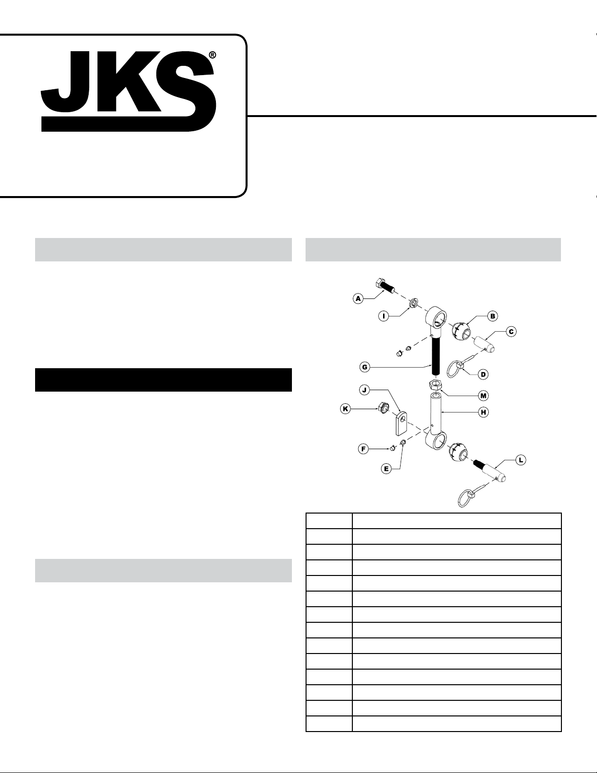
A
B
C
D
E
F
G
H
J
K
L
M
Parts
Description
1/2” x 1-3/8” NF GR5 Bolt
Spherical Bushing
Upper Stainless Steel Post
Click Pin
Press-In Grease Zerk
Grease Zerk Cap
Upper Male Threaded End
Lower Female Threaded End
I
1/2” Lock Washer
Weld-on Tab
1/2” NF Nylock Nut
Lower Stainless Steel Post
5/8” Jam Nut
Page 1
Page 2
Installation
1. REMOVE ORIGINAL EQUIPMENT (OE)
SWAYBAR LINKS
Remove front swaybar drop links and mounting
hardware per the factory service manual instructions for your vehicle.
2. INSTALL UPPER TAPERED POST
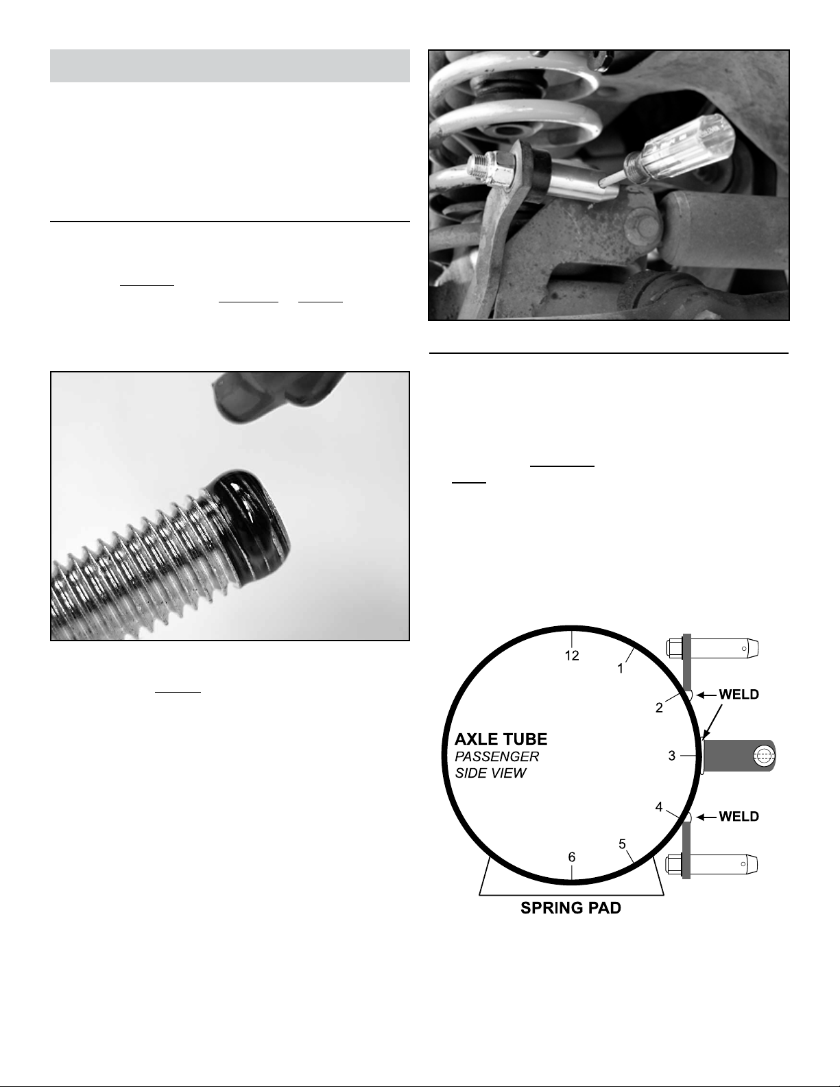
Mount the tapered Upper Stainless Steel Post (C)
on outboard side of the swaybar, ensuring small
Click Pin holes are horizontal or parallel with the
ground.
Apply medium strength threadlocker to the tip of
1/2” x 1-3/8” Bolt (A).
3. DETERMINE MOUNTING LOCATION FOR
WELD-ON TAB
It will be necessary to weld the lower mounting tab directly to the front axle housing. The base of the tab can
be positioned in the 2-, 3-, or 4-o’clock conguration as
viewed from the passenger side (8-, 9-, or 10-o’clock from
the driver side). HI NT: The position of the mounting tab will
depend on the vehicle and amount/type of suspension lift
installed.
Secure tapered post to swaybar by inserting the
1/2” x 1-3/8” Bolt (A) and 1/2” Lock Washer (I)
from the inboard side and tighten to 65 ft-lb. using
a torque wrench.
HINT: A small Philips head screwdriver or punch
inserted into the Click Pin hole will enable you
to prevent the Stainless Steel Post from rotating
when tightening the mounting bolt.
HINT: For easiest operation, the tapered mounting post
should point forward as illustrated in the 2- or 4-o’clock
conguration. Alternatively, a perpendicular mounting position (as illustrated in the 3-o’clock conguration) may also
be utilized in tight clearance applications.
2 Page
JK S4100
JKS Quicker Disconnect Installation
Page 3
To determine the proper location for the lower
mounting tab, temporarily slide the Upper End (G)
of Quicker Disconnect onto the Upper Stainless
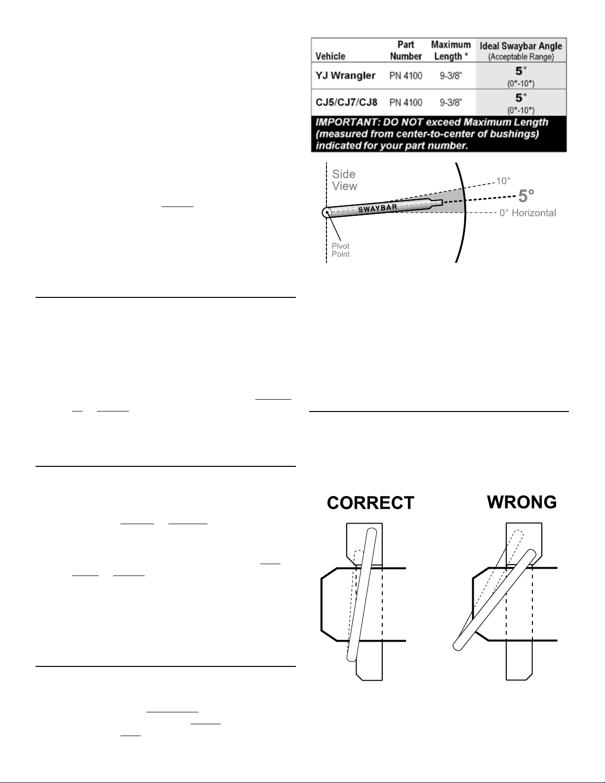
Steel Post (C) and adjust angle of swaybar to Acceptable Range (0°-10°). H I N T: Refer to Step 6 on
next page for illustration of swaybar angle.
Temporarily insert the threaded end of Lower
Stainless Steel Post (L) into Weld-on Tab (J) and
secure with 1/2” Nylock Nut (K). Slide tab and post
assembly into Lower End (H) of Quicker Disconnect.
Choose the conguration for the Lower Mount-
ing Tab that allows the Quicker Disconnect to be
installed as close to vertical as possible. Length
of Quicker Disconnect may be adjusted as long
as it does NOT exceed Maximum Length of 9-3/8”
(measured from bushing centers).
Mark the location on the axle tube where Weld-on
Tab (J) will be installed.
4. MOUNT WELD-ON TAB TO AXLE TUBE
Remove tab and post assembly from Lower End
(H) of Quicker Disconnect and disassemble.
Remove paint from axle tube where Weld-on Tab
(J) will be mounted and clean area thoroughly.
Weld lower mounting tab to axle tube so that
Stainless Steel Post – when installed – is horizontal or parallel with the ground.
Paint Weld-on Tab (J) and any bare metal on axle
tube with spray paint to prevent corrosion.
5. INSTALL LOWER TAPERED POST
Re-insert threaded end of Lower Stainless Steel
Post (L) into Weld-on Tab (J). Tapered end of post
must point forward or outboard, depending on the
mounting conguration chosen.
Secure Stainless Steel Post (L) with 1/2” Nylock
Nut (K), ensuring small Click Pin holes are horizontal or parallel with ground.
Tighten 1/2” Nylock Nut (K) to 65 ft-lb. using a
torque wrench. H I NT: A small Philips head screw-
driver or punch inserted into the Click Pin hole
will enable you to prevent the Stainless Steel Post
from rotating when tightening the mounting bolt.
IMPORTANT: DO NOT exceed Maximum Length (measured from center-to-center of bushings) indicated for
your part number.
Once adjusted, lay Quicker Disconnects on a at
surface and tighten Jam Nuts (M) rmly against
the Lower Ends (H).
IMPORTANT: Bushing cradles at both ends of Quicker
Disconnect must remain parallel with their respective
mounting posts when Jam Nut is tightened.
7. INSTALL QUICKER DISCONNECTS
Slide Upper End (G) of Quicker Disconnect onto
the Upper Stainless Steel Post (C) and Lower End
(H) onto Lower Stainless Steel Post (L).
Insert Click Pins (D) as illustrated to secure.
6. SET QUICKER DISCONNECT LENGTH
Adjust the length of your Quicker Disconnects until
swaybar is at the Ideal Angle or within Acceptable
Range. Vehicle must be at normal ride height and
located on level ground.
IMPORTANT: When properly installed, the ring on the
Click Pin will “snap” against the shaft of pin. When in-
stalled backwards, the ring does not t snugly against
shaft.
JK S4100JKS Quicker Disconnect Installation
Page 3
Page 4
8. LUBRICATE QUICKER DISCONNECTS
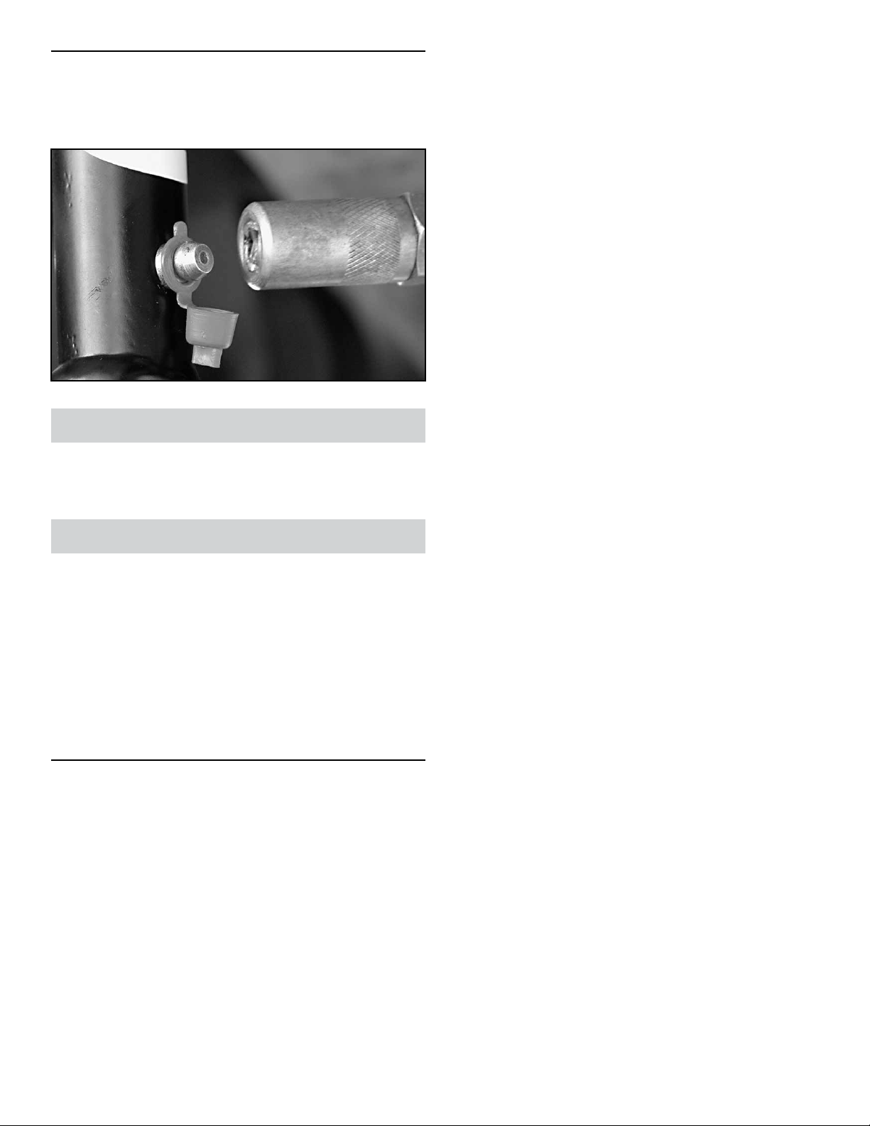
Lubricate all Grease Zerk ttings (E) on the Quick-
er Disconnects immediately after installation using
common wheel bearing grease or equivalent.
Troubleshooting
If swaybar does not rotate freely, remove from vehicle,
clean and apply rubber lubricant to chassis-mounted bushings, and reinstall.
Maintenance
It is important to lubricate Quicker Disconnects frequently
for the rst three (3) months after installation to evacuate
contaminants that may build up during break-in period.
After break-in period, Quicker Disconnects should be lubricated regularly as part of vehicle maintenance schedule.
Regular cleaning with pressurized water is recommended
to maximize ease of operation and reliability. Always lubricate afterwards to evacuate any moisture.
©2013 JKS Manufacturing, Inc & Aftermarketing, LLC
Revision Date 10/11/2013
4 Page
JK S4100
JKS Quicker Disconnect Installation
 Loading...