

Page 1
INSTALLATION
INSTRUCTIONS
517-278-1226 • [email protected] • www.jksmfg.com
491 W. Gareld Avenue, Coldwater, MI 49036
Product: Adjustable Coil Spacers (ACOS™)
Part Number: JKS2210
Welcome
CONGRATULATIONS on your purchase of a new JKS
ACOS™ system! At JKS Manufacturing, we are committed
to providing you with the best products available and your
satisfaction is our rst priority.
PLEASE READ these Installation Instructions carefully,
and save them for future reference, as they contain impor-
tant installation and maintenance information.
Tools Required
Hydraulic Floor Jack and Jack Stands
Metric/Standard Socket Wrench Set
(including a 17mm socket)
6” Socket Extension
8mm and 1/4” Allen Wrenches
Die Grinder with Cut-Off Wheel
(or reciprocating saw)
Grinding Wheel (or similar tool)
File or Deburring Tool
Emory Cloth (or similar paint stripping tool)
1/4” Drill Bit
Rubber or Plastic Mallet *
Tape Measure
Spray Lubricant (WD-40 or similar)
Anti-Seize Lubricant
Medium Strength Threadlocker
Coil Spring Compressor *
Factory Service Manual (recommended)
* Asterisk denotes tools that are not required for some applica-
tions. Thoroughly read instructions rst to determine which tools
will be required for your application.
Important
MOST VEHICLES REQUIRE additional parts or modi-
cations to accommodate the immediate increase in
ride height provided by the ACOS system.
DO NOT EXCEED maximum range of adjustment – see
illustration on page 3.
NOT COMPATIBLE with Rancho, TrailMaster, Rough
Country or Fabtech coil springs.
Parts
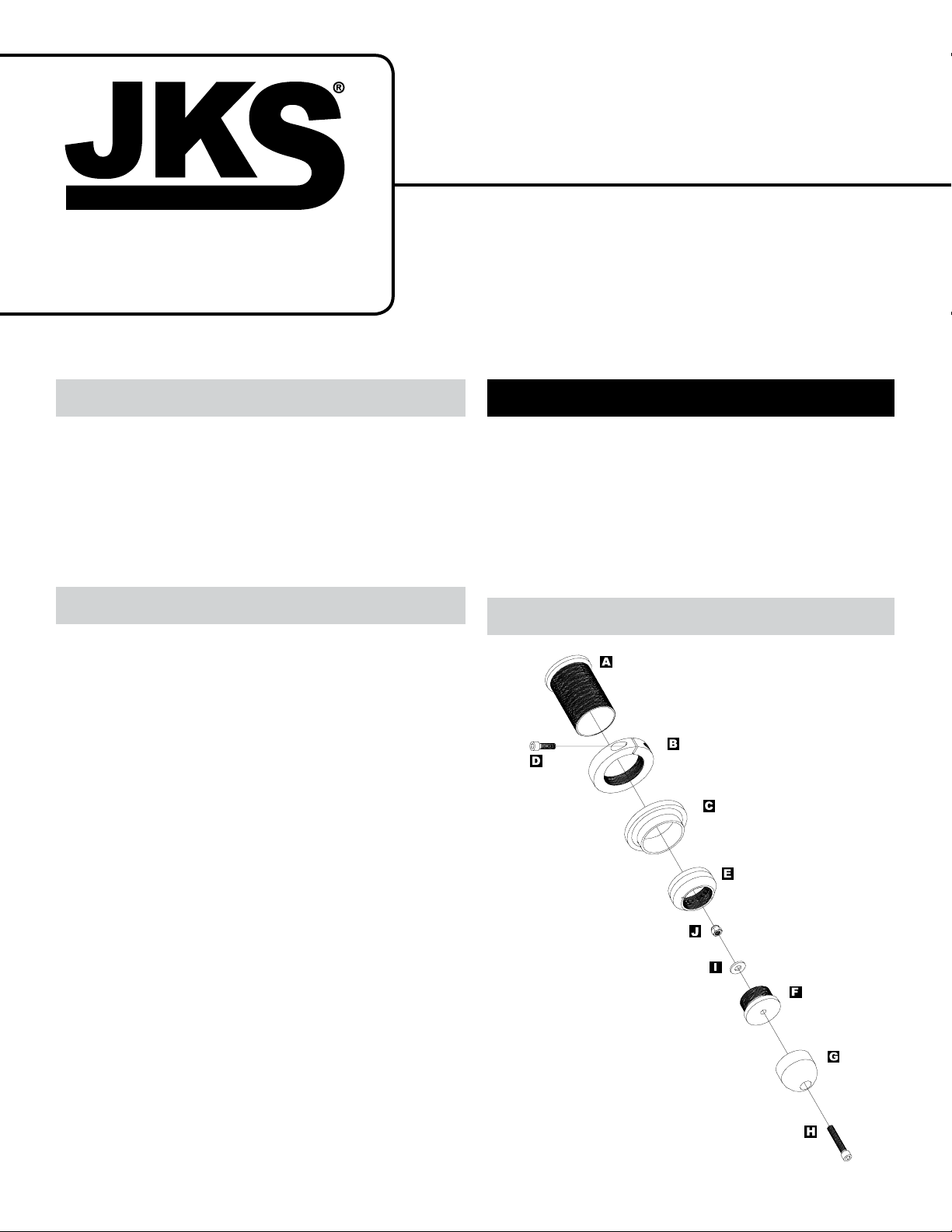
JKS2 210JKS Adjustable Coil Spacer Installation
Page 1
Page 2
Description QTY
A
Threaded Tube 2
B
Adjuster Ring 2
C
Isolator Pad 2
D
5/16” x 1-1/4” Cap Bolt 2
E
Bump Stop Adapter 2
F
Bump Stop Plug 2
G
Polyurethane Bump Stop 2
H
10mm x 55mm Cap Bolt 2
I
3/8” Flat Washer 2
J
10mm Locking Nut 2
Installation
1. REMOVE FRONT COIL SPRINGS
Remove the front coil springs per the factory ser-
vice manual instructions for your vehicle.
HINT: A coil spring compressor is useful for removal.
Depending on the application, it may be necessary to completely or partially remove any of the
following components before spring can be free
from upper mount.
 Shock Absorber
 Swaybar
 Brake Line
 ABS Wire
Locate the factory weld that secures the bump
stop holder to the upper coil spring retainer.
2. PREPARE SPRING RETAINER
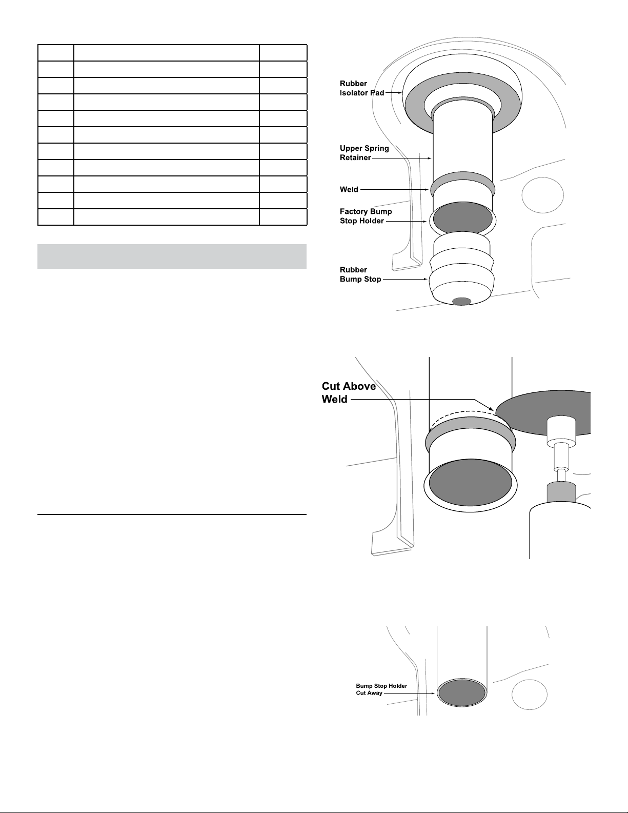
The factory bump stop holder is welded to the upper spring
retainer and must be permanently removed in order to
install the ACOS™.
Pry the rubber bump stop (jounce bumper) free
from the bump stop holder.
Remove the rubber isolator pad from the upper
coil spring retainer.
2 Page
JKS2 210
Cut away the bump stop holder immediately above
the weld as illustrated. HI NT: A die grinder with
cut-off wheel or reciprocating saw is useful for cutting away the bump stop holder.
Remove any sharp edges from the cut portion of
the upper spring retainer. HINT: A le or deburring
tool is useful for removing sharp edges.
JKS Adjustable Coil Spacer Installation
Page 3
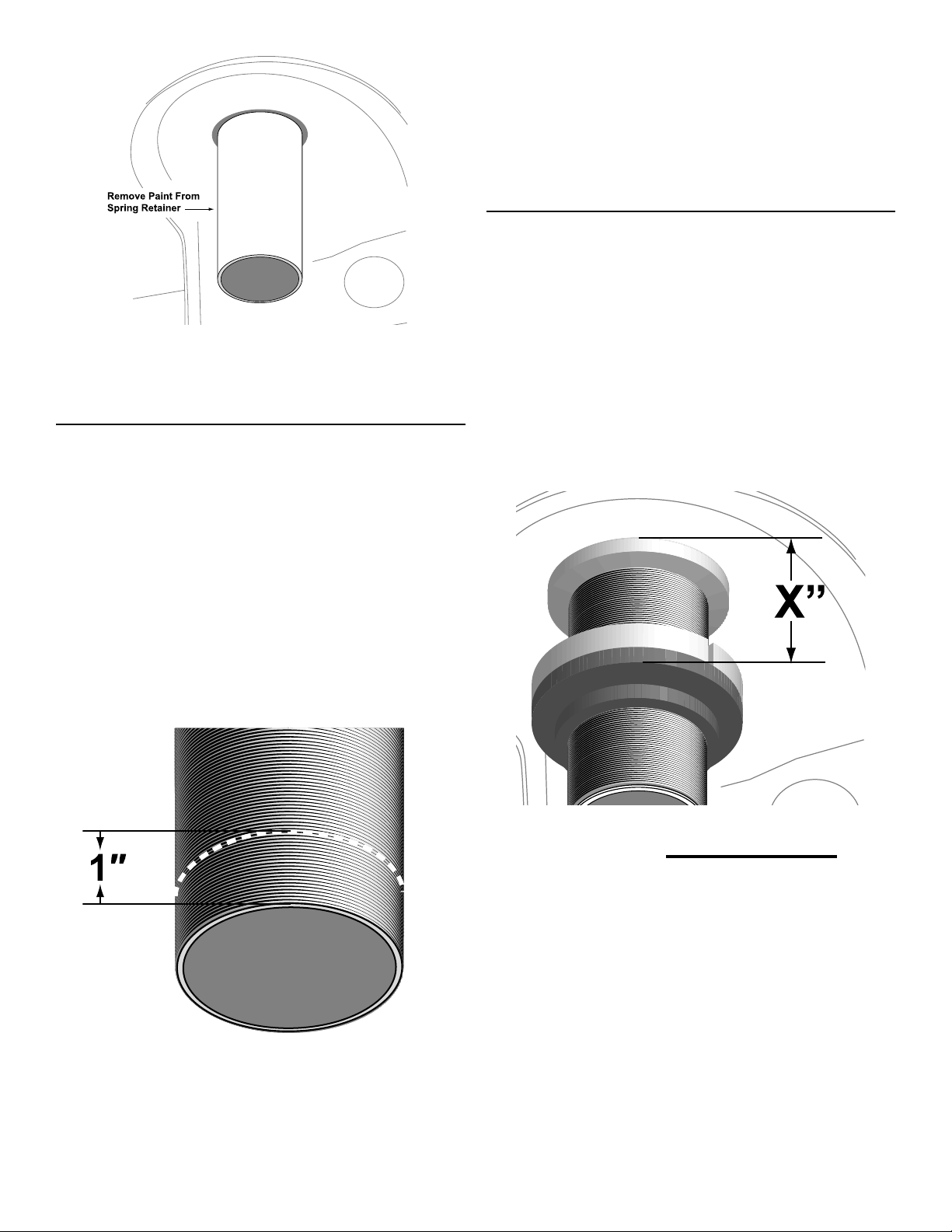
Remove all of the factory paint from the surface of
the upper spring retainer. HINT: Emory cloth or a
suitable stripping tool is useful for paint removal.
3. SHORTEN THREADED TUBE OF ACOS
On vehicles with a net lift height of less than 1", it will
be necessary to shorten the Threaded Tube (A) to provide sufcient clearance between the Bump Stop (G)
and the axle pad. This step will reduce the maximum
adjustment height from 3.5" to 2.5". Example situation: Coils have sagged 1" below stock as a result of a
heavy bumper, ACOS installed to reset ride height to
factory - will require this trimming procedure. If you
have questions about your application or this modication please contact JKS Manufacturing Tech Support.
may also be used. Use extreme care to avoid
damaging remaining threads.
Inspect end of Threaded Tube (A) for damaged
threads and repair as needed. H I N T: A 16TPI
thread restoring le or equivalent is useful for
repairing threads.
4. SET ADJUSTER RING FOR DESIRED
RIDE HEIGHT
Apply spray lubricant to threads of Threaded Tube
(A).
Install Adjuster Ring (B) by threading it onto the
Threaded Tube (A).
Slide Isolator Pad (C) onto Threaded Tube (A) until
ush with Adjuster Ring (B).
IMPORTANT: Vehicle ride height is determined by
measuring the distance between the bottom of upper
spring mount and bottom of Isolator Pad, and then
subtracting 1/2” (0.50 in.).
Measuring 1.0” from the threaded end, mark a line
on the Threaded Tube (A).
Remove the excess portion by cutting completely
through the Threaded Tube (A) at the location
marked in the previous step. HINT: A band saw is
useful for cutting the
Threaded Tube, although a sharp hack saw with
an appropriate ne tooth blade or cutting wheel
X" - 1/2" = RIDE HEIGHT*
* Represents increase in ride height over OE Suspension
JKS2 210JKS Adjustable Coil Spacer Installation
Page 3
Page 4
WARNING
DO NOT EXCEED
MAXIMUM RANGE OF ADJUSTMENT
Adjustment Range*
Minimum: 1" (1.0 in)
Maximum: 3-1/2" (3.5 in.)
Rotate Adjuster Ring (B) to desired position and
tighten the recessed 5/16” x 1-1/4” Cap Bolt (D) to
lock in place.
5. INSTALL BUMP STOP ON THREADED
TUBE OF ACOS
Apply a drop of medium strength thread locking
compound to bottom few threads of Threaded
Tube (A).
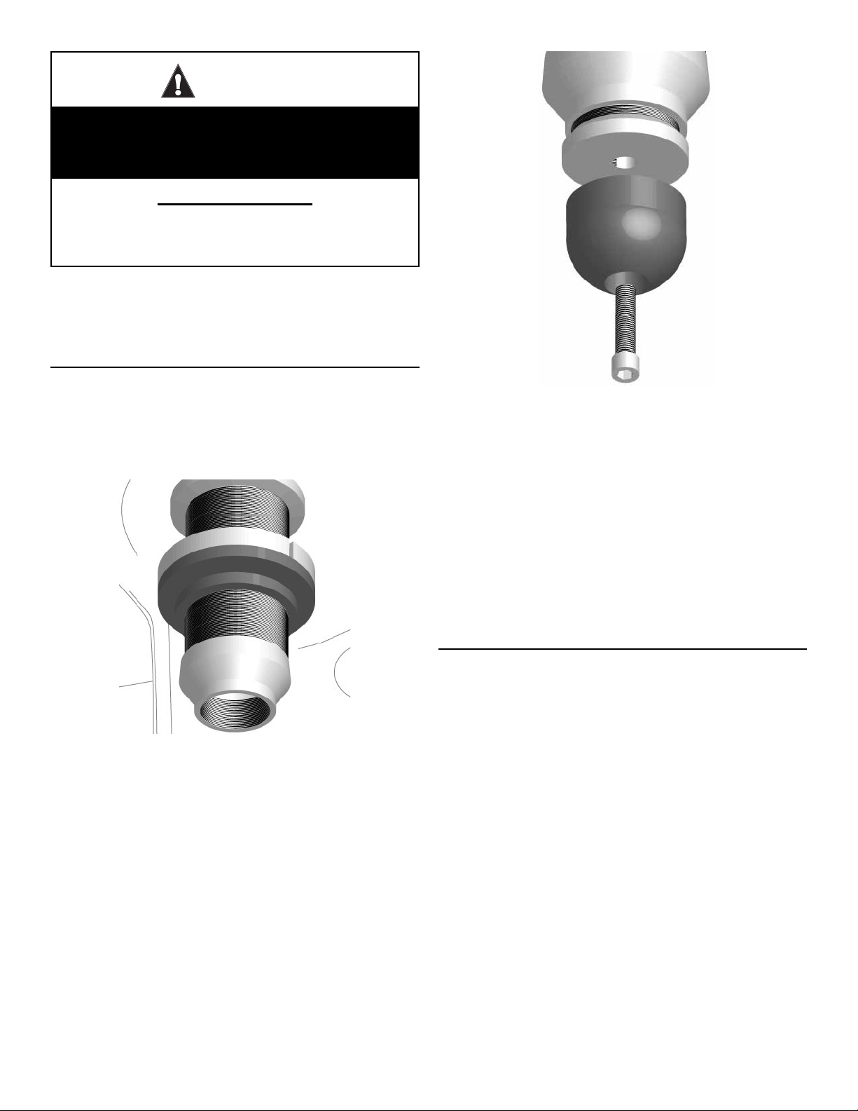
Install Bump Stop Adapter (E) onto Threaded Tube
(A) and tighten by hand until snug.
IMPORTANT: If ange end of Threaded Tube (A) begins
to pull away from the upper spring mount before the
Bump Stop Adapter (E) is completely installed, turn
the Bump Stop Adapter counter-clockwise one full
turn and reseat Threaded Tube against upper spring
mount.
x
Secure the Polyurethane Bump Stop (G) to the
Bump Stop Plug (F) by installing the 3/8” Flat
Washer (I) and 10mm Locking Nut (J) from above
the upper spring mount.
HINT: To install the 3/8” Flat Washer and 10mm
Locking Nut, tape them onto a 17mm socket at-
tached to a 6” long socket extension and lower into
the access hole located above the upper spring
mount.
Slowly tighten 10mm x 90mm Cap Bolt (H) until
the sides of the Polyurethane Bump Stop (G) begin
to bulge. Do NOT overtighten!
6. RE-INSTALL FRONT COIL SPRINGS
Re-install the front coil springs per the factory ser-
vice manual instructions for your vehicle.
HINT: A coil spring compressor is useful for installation.
Also re-install any of the components that were
removed during the REMOVE FRONT COIL
SPRINGS section of this installation.
Apply anti-seize lubricant to threads of Bump Stop
Plug (F).
Install Bump Stop Plug (F) by threading it com-
pletely into the Bump Stop Adapter (E).
Insert the 10mm x 90mm Cap Bolt (H) into the
recessed hole in Polyurethane Bump Stop (G) and
through the hole in the bottom of the Bump Stop
Plug (F).
4 Page
JKS2 210
JKS Adjustable Coil Spacer Installation
Page 5
ATTENTION INSTALLER
IMPORTANT NOTE REGARDING
SHOCK ABSORBERS
To prevent the coil springs from becoming
unseated during maximum suspension
extension, correct length shock absorbers
must be installed.
Operation
Ride Height Adjustments
Future ride height adjustments should be made
with NO LOAD on the front coil springs, and the suspension at FULL DROOP.
NEVER TURN Adjuster Ring (B) while under tension
and ALWAYS APPLY SPRAY LUBRICANT to Threaded
Tube (A) before adjusting.
Maintenance
Regular cleaning with pressurized water is recommended
to maximize ease of operation and reliability.
In addition, the Bump Stop Adapter (E) has two 1/8” drainage holes that evacuate any water collected inside the
upper spring retainer. Periodically check for blockages and
clear the drainage holes if necessary.
©2014 JKS Manufacturing, Inc & Aftermarketing, LLC
Revision Date 5/15/2014
JKS2 210JKS Adjustable Coil Spacer Installation
Page 5
 Loading...