

Page 1
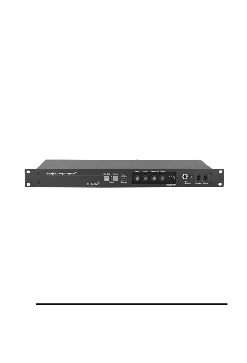
PBXport
Rackmount PBX
Digital Hybrid
User Guide
JK Audio
Page 2

Introduction
PBXport will allow you to send and receive audio through your multiline PBX, ISDN or analog telephone. While this may seem like a simple task, the challenge is getting the best quality audio from such a
limited audio path.
What is a Digital Hybrid?
The PBXport digital hybrid connects audio signals to and from the
handset side of a telephone without the variations in quality found
with analog hybrids. The main function of a hybrid is to bring in the
caller’s voice from the phone line, as clear and clean as possible. In
the real world, when you send your voice down the telephone line it
has a tendency to bleed over into the caller’s audio. The hybrid must
adapt to the audio signals from the telephone in order to properly
separate transmit and receive audio. We use a 16 bit DSP (Digital
Signal Processor) to continuously monitor the audio signals from the
telephone to deliver excellent separation. Our dual-convergence
algorithm can achieve excellent trans-hybrid loss, also known as
"separation".
Ready to go?
The PBXport controls and connectors are clearly marked and ready
for operation. The feature diagram will help you pinpoint any minor
questions that you may have. If this is your first exposure to a hybrid,
we suggest that you read the entire manual to allow you to take advantage of all these features.
Any Questions?
Before you pick up the phone... Please thumb through the rest of this
manual. You might find those deep technical questions are covered
on later pages.
Safety Symbols used in this manual:
ATTENTION! - Alerts you to instructions for preventing a
situation that could result in damage to the unit.
WARNING! - Alerts you to instructions for preventing a poten-
tially hazardous situation that could result in bodily injury.
2
Page 3
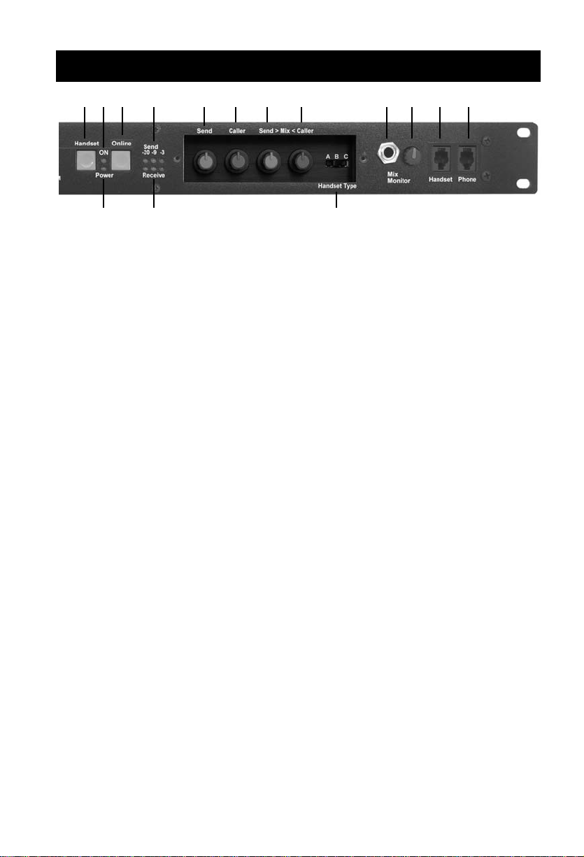
Features—Front View
1 2 3 4 5 6 7 8 9 10 11 12
13
1. Handset Button - Press this button to use the handset as on a normal
phone call.
2. ON LED - Lit when you are online with a call using the digital hybrid.
3. Online Button - Press this button to disable the handset and activate the
PBXport for use as a digital hybrid.
4. Send LEDs - Displays the signal level going out to the telephone line.
5. Send Level - Adjusts the signal level that you are sending down the telephone line, through the female XLR input.
6. Caller Level - Adjusts the level of the signal coming in from the telephone
line, going out the output jacks.
7. Send>Mix Level - Adjusts the level of local Send audio going out the Mix
output jack.
8. Mix<Caller Level - Adjusts the level of signal coming in from the telephone line, going out the Mix output jack.
9. Mix Monitor jack - 1/4" stereo headphone jack containing the same mix
as the Mix output jack.
10. Mix Monitor Level - Adjusts the signal level of the 1/4" headphone jack
and the speaker terminals.
11. Front Panel Handset Jack - Connect your telephone handset to this jack
or the rear panel handset jack.
14 15
12. Front Panel Phone Jack - Connect the handset jack on your telephone
base to this jack or the rear panel phone jack using the supplied handset
jumper cable.
13. Power LED - Lit when the unit is plugged in and receiving power.
14. Receive LEDs - Displays the signal level coming from the phone line,
after the DSP.
15. Handset Type Selector Switch - Use this switch to select the correct type
of handset microphone that your telephone uses. A=Electret, B=Carbon,
C=Dynamic.
3
Page 4
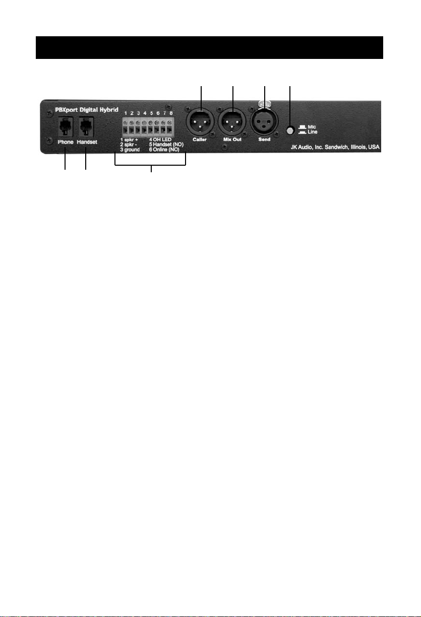
Features—Rear View
16 17 18 19
20
21
16. Caller Output - Male balanced XLR output contains caller audio from the far side of the call.
17. Mix Output - Male balanced XLR output contains Caller and/or
Send audio based upon Send>Mix<Caller volume control settings.
18. Send Input - Female balanced XLR input for signals going into
the phone line. Mic or line level input. This jack does not provide phantom power.
19. Mic / Line switch - Sets the front end sensitivity of the Send
XLR input. Set to Mic if you intend to plug a microphone directly to the Send jack. Set to Line if you are connecting to the
line output or auxiliary output of a mixer or other audio equipment.
20. Rear Panel Phone Jack - Connect the handset jack on your
telephone base to this jack or the front panel phone jack using
the supplied handset jumper cable.
21. Rear Panel Handset Jack - Connect your teleph one handset to
this jack or the front panel handset jack.
22. Screw Terminal Block - For speaker connection, remote LED
status connection and remote Online / Handset control.
22
4
Page 5
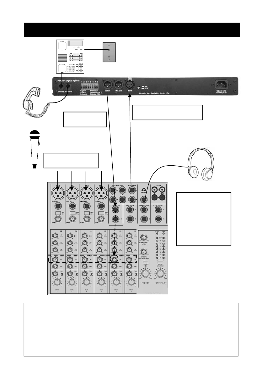
Connection—Mix-Minus Setup
Aux Send to Send 1,
Caller to any
line level input
Number of mics
depends on mixer
Mic/Line button in (Line)
Use Main Outputs,
USB or Firewire
connectors to
send audio to
recording device,
or broadcasting
equipment inputs
For whichever input channel you have the Caller connected to, turn the
corresponding Aux control to minimum (usually hard left). All other Aux
controls should be set for what you want to send to the phone line. Each
Aux Send bus is completely separate from all other outputs, so these Aux
controls will not affect what is heard on the Main outputs or on any other
Aux buses. This Aux Send bus should be pre-fader, so you can use the
fader controls to set the levels of each channel to the main output.
5
Page 6

Operation
Connecting Cables
Although each application will require a slightly different
setup, standard configuration is as follows:
Handset cable - Connect the supplied RJ-22 handset cable
between the jack marked "Phone" on the front or back of
PBXport and to the handset jack on the base of your telephone.
Handset - Connect your telephone handset to the RJ-22 jack
on the front or back of the PBXport marked "Handset". You
must keep a handset connected at all times, even when you
are not using it.
Send Audio - Connect a microphone directly or a mixing console mix-minus output to the Send jack on the PBXport. Be
sure to set the PBXport mic/line switch to the proper position
for your application. Mic = microphone connected directly,
Line = line level output from your audio equipment. More
about mix-minus on page 5.
Caller Audio - Connect the Caller Out jack to a line level input
on your mixing console or audio equipment.
Power - Connect the supplied AC power cable to the back of
the PBXport and then to an AC power outlet.
Your PBXport is now ready to take calls.
PBXport will disable the telephone handset microphone when
you press the Online button. Use your telephone to place or
screen a call. When you are ready to take the call on
PBXport, simply press the Online button. Make sure you do
not put the handset back in it's cradle while you are on a call.
This will still drop the call even though the handset itself is
disabled. If you need to take the call back on your telephone,
simply press the Handset button on PBXport. This will disable
6
Page 7

Operation (continued)
the Mix<Caller and Caller output on PBXport and connect
your handset back to the telephone. Any audio sent into the
Send input will still be active on the Mix output based upon
your settings.
Send Signal Level
The Send LEDs display the signal level as it goes out over
the phone line. The goal is to drive the phone line at high
enough levels to avoid phone line noise, but not so loud as to
cause excessive clipping. Adjust the send level control until
you see occasional flashes of the red -3dB peak Send LED.
These flashes should occur during loud speech bursts only. If
the red LED stays lit for extended periods you can assume
that much of your speech is being clipped or distorted. In this
case you should back down on the Send volume control or
the mixer output that is causing the clipping.
Receive Signal Level
The receive LEDs display the signal coming from the phone
line and out of the DSP. The Caller level control does not
change what you see on these LEDs. Adjust the Caller level
control to give you the best signal level at the output XLR. If
your telephone has an adjustable receiver volume control,
you should set this control to the "normal" position. If you attempt to boost the level of the caller's voice using the handset
volume control on your telephone, you may cause PBXport to
become unstable. This instability would be caused by the increased level of the transmit signal that becomes mixed with
the caller's voice.
Headphone Mix
The 1/4" headphone jack on the front of PBXport is used for
monitoring your call. This stereo jack contains a mix of both
sides of the conversation on each headphone channel. The
levels of this mix are determined by the Send>Mix<Caller volume controls. The overall audio level from this jack is determined by the Mix Monitor volume control.
7
Page 8

Operation (continued)
A-B-C Selector Switch
Use this switch to select the correct type of handset microphone that your telephone uses. A=Electret, B=Carbon,
C=Dynamic. Trial and error seems to work best in determining which handset type to use. Your PBXport will only function correctly if the handset type selector switch is in the correct position. This switch changes signal level, impedance,
and wiring to accommodate the differences in handset microphone types.
In order to determine the correct position, you must place a
call to a nearby telephone, then try to send audio into the
PBXport through the inputs. While doing this, switch between
the three different handset type positions. Choose the position that works best by monitoring the audio quality and send
LED's. You may need to readjust the Send audio level for
each setting.
Although not conclusive, the following guidelines may help:
The majority of newer telephones have electret type micro-
phones and will use the "A" position.
Older telephones that have the round "screw-on type" hand-
sets contain carbon microphones and use the "B" position.
Many Radio Shack®, Panasonic®, and Nortel® telephones
have dynamic microphone types and use the "C" position.
8
Page 9

Operation (continued)
Operation (continued)
Optional Jumper Settings
If your unit was purchased after December 2007, there are
two jumpers located on the circuit board inside the PBXport
that affect your incoming audio. The jumper at J10 allows you
to completely disable both the handset microphone and
speaker when the Online button is pressed. The factory default closed position disables only the handset microphone
when the Online button is pressed. This will have no affect on
normal telephone operation.
If the incoming audio level from your telephone is too high
and you are consistently lighting the red –3 dB Receive LED,
first try decreasing the volume using the controls on the base
of your telephone. If you still cannot drop the incoming audio
level enough, you may need to change jumper J11. There
are three possible settings to adjust Caller Receive level:
Pins 1 & 2 closed = 0 dB (factory default)
Pins 2 & 3 closed = -10 dB
Pins 1-3 left open = -20 dB
To change the jumper settings, first disconnect power from
the PBXport, then remove the top cover on the unit. Locate
the appropriate jumper on the printed circuit board and set to
the desired position.
WARNING! The AC cable must be unplugged from
the back of PBXport anytime the case is opened. Failure to follow these instructions could potentially result
in injury or death.
ATTENTION! Be sure to use an ESD grounding
wrist strap when changing this jumper setting. If you
do not have a wrist strap, keep one hand on the
PBXport case at all times while changing the jumper
with the other hand. These measures are required to
prevent electrostatic discharge from damaging the
unit.
9
Page 10

FAQs
? Will PBX Port work with my __________ PBX phone
system?
! Probably yes. We have to say probably because the
handset interface is proprietary and therefore can
change from model to model. We have no way of predicting how a phone manufacturer will use the handset
wires in the future. The three handset microphone types
that we support, electret, dynamic, and carbon, cover
every handset microphone type that we have seen in
use, but the wire diagrams can change without notice.
? Can PBX Port auto-answer or auto-disconnect?
! No, the handset cord on your telephone is only active
when the handset is off-hook. This is done manually.
There is no way then to auto-disconnect. You must return the handset to the cradle.
? Why can’t I dial out on my phone? or I hear a lot of
noise on the call?
! PBX Port will not work with any telephone that has a
keypad in the handset. You need to use a telephone
with a standard handset.
? I have everything connected correctly. Why can’t the
caller hear me?
! This could be one of two things. First, check the position
of the A-B-C switch. Most phones use either setting A or
C. If you cannot send any audio with setting A, you
should use setting C.
Also, you cannot use the speakerphone function on your
telephone during your recording. PBX Port accesses
the audio path through the handset cord. With the
speakerphone turned on, there is no audio going to the
handset.
10
Page 11

FAQs
? How do I connect a call through PBXport? Every
time I press the “Online” button, the call is disconnected.
! If you put the handset back in the cradle on the tele-
phone, it will depress the hook flash button on the phone
and your call will be disconnected. You should set the
handset down beside the telephone and only return it to
the cradle after your call is completed. You need to
leave the handset connected to one of the Handset
jacks on PBXport to maintain the correct impedance for
your telephone.
? The PBXport is not providing any/enough separa-
tion of Send and Caller audio.
! The A-B-C handset type selector switch must be set to
the correct position to send audio into the telephone.
Setup for this is covered on page 8. If you are connecting the PBXport input and output(s) to the same device,
you must send a “mix-minus” signal into the Send jack
from your equipment. This setup is covered on page 5.
? Will PBX Port provide phantom power for my con-
denser microphone?
! No, our devices will not provide phantom power. If you
are connecting your microphone directly to PBX Port,
you should use a dynamic mic.
11
Page 12

Other Information
Screw Terminal Block
1 - Speaker (+) Minimum 8 ohms, 1 watt max
2 - Speaker (-) Use together with terminal 1
3 - Ground
4 - OH LED Supplies +4.3 VDC, 40 mA steady signal during
an Online call.
5 - Online (NO) Pull this pin to ground momentarily to simu-
late pressing the
Online button.
6 - Handset (NO) Pull this pin to ground momentarily to
simulate pressing the Handset button.
Contact your JK Audio dealer for additional information.
Helpful Hints:
PBXport will not work with any telephone that has a keypad
in the handset.
If using a mixer you must use a "mix-minus" signal to the
Send input (Page 5)
You must set the A-B-C switch to the correct handset type
position for your particular telephone. (page 8)
You may use either front or back panel handset jacks but not
simultaneously.
Don't overdrive the Send input. Flashes of the -3 Red Send
LED indicate distortion, clipping and reduced separation.
If your telephone has an adjustable receiver volume control,
you should set this control to the "normal" position. If the
Receive audio meter on the PBX port is showing the red
–3 dB LED, you should turn down the volume on the base
of your telephone until you see only green LEDs.
12
Page 13

Specifications
Inputs:
Send Input: Female XLR 1 k ohm, 10 mV
RMS nom. (-38 dBu nom.)
Mic/Line pad switch
Line = +5 dBu nom.
Outputs:
Caller Out: Male XLR 200 ohms,
500 mV RMS nom.
(+14 dBu Max output)
Mix Out: Male XLR 200 ohms,
500 mV RMS nom.
(+14 dBu Max output)
Headphone: 1/4" Stereo 8 ohms,
250 mW per channel.
Speaker: Screw Terminals 8 ohms,
1 watt max
Handset Connectors: RJ22
Phone Base Connectors: RJ22
Power: 100-240 VAC, 50-60 Hz
Isolation: 1500 VAC
Size: 19" x 7.3" x 1.75"
(48.3 x 18.6 x 4.5 cm)
Weight: 5.4 pounds (2.4 kg)
13
Page 14

FCC Part 15 Compliance
This equipment has been tested and found to comply with
the limits for a Class A digital device, pursuant to Part 15 of
the FCC Rules. These limits are designed to provide
reasonable protection against harmful interference when the
equipment is operated in a commercial environment. This
equipment generates, uses, and can radiate radio frequency
energy and, if not installed and used in accordance with the
instruction manual, may cause harmful interference to radio
communications. Operation of this equipment in a residential
area is likely to cause harmful interference in which case the
user will be required to correct the interference at his own
expense.
Changes or modifications not expressly approved by JK
Audio can void the user's authority to operate the equipment.
FCC Registration
Your new JK Audio product has been registered with the
Federal Communications Commission (FCC). This product
complies with the standards in Part 68 of the FCC rules.
1. Connection and use with the nationwide telephone
network
The FCC requires that you connect this telephone
equipment to the national telephone network through a
USOC RJ-11C modular telephone jack.
This equipment may not be used with Party Line Service
or Coin Telephone Lines.
This equipment is hearing aid compatible.
2. Information for the telephone company
Upon request from your local telephone company, you
are required to provide the following information:
a) The "line" to which you will connect the telephone
equipment (that is, your telephone number), and
b) The telephone equipment's FCC registration number.
14
Page 15

FCC Registration (continued)
This can be found on the bottom of your telephone
equipment, and,
c) the ringer equivalence number (REN) for this
equipment. The REN is used to determine the quantity of
devices which will be connected to the telephone line.
Excessive RENs on the telephone line may result in the
devices not ringing in response to an incoming call. In
most, but not all areas, the sum of the RENs should not
exceed 5.0. To be certain of the number of devices that
may be connected to the line, as determined by the total
RENs, contact the local telephone company.
3. Repair Instructions
If it is determined that your telephone equipment is
malfunctioning, the FCC requires that it not be used and
that it be unplugged from the modular outlet until the
problem has been corrected. Repairs to this telephone
equipment can only be made by the manufacturer or its
authorized agents or by others who may be authorized by
the FCC. For repair procedures, follow the instructions
outlined under the warranty section of the manual.
4. Rights of the telephone company
If telephone equipment is causing harm to the network,
the telephone company may temporarily discontinue your
telephone service. If possible, they'll notify you before
they interrupt service. If advanced notice isn't practical,
you'll be notified as soon as possible. You'll be given the
opportunity to correct the problem, and you'll be informed
of your right to file a complaint with the FCC.
Your telephone company may make changes in its
facilities, equipment, operations or procedures that could
affect the proper functioning of your JK Audio product. If
such changes are planned, you'll be notified by your
telephone company.
15
Page 16

Warranty
PBXport is covered by a 2-year warranty to be free from
defective workmanship and materials. In the event that the
PBXport needs repair, you must call us to get an
authorization, and then carefully pack and ship it to us. You
will pay for shipping to us and we will pay for return back to
you, UPS ground. No free repairs will be made if the defect
was caused by misuse, weather conditions, or other cause,
except for defective workmanship or materials.
THERE ARE NO EXPRESSED OR IMPLIED
WARRANTIES WHICH EXTEND BEYOND THE
WARRANTY HERE MADE.
11/07
JK Audio, Inc. 1311 E 6th Street, Sandwich, IL 60548 USA
Voice: (815) 786-2929 Toll Free: 800-JK-Audio Fax: 815-786-8502
Info@jkaudio.com www.jkaudio.com
Copyright © 2006 JK Audio. All Rights Reserved.
 Loading...